Page 426 of 5267
*CHECKING THE FUEL DELIVERY SYSTEM
For a complete wiring diagramRefer to Section 8W.
Page 429 of 5267

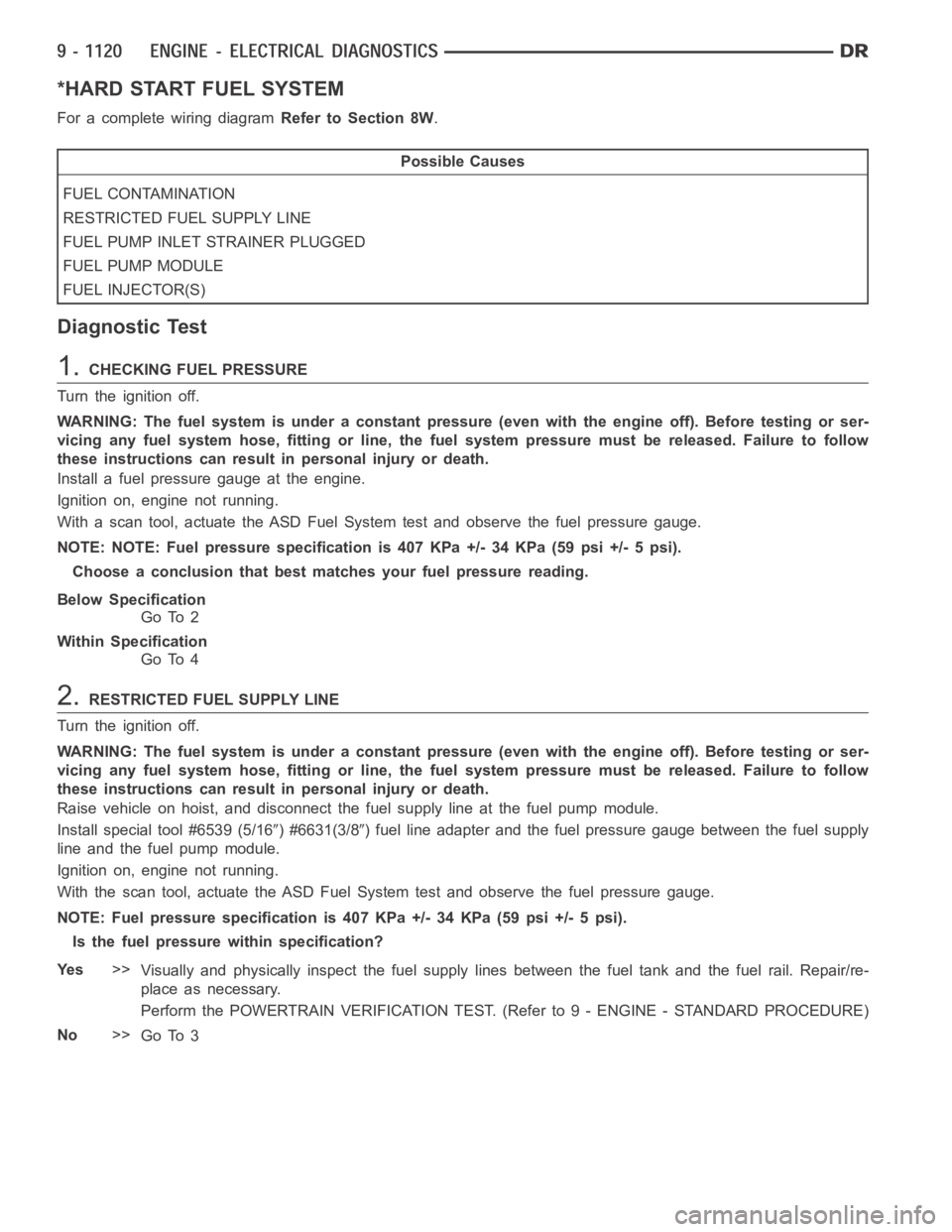
*HARD START FUEL SYSTEM
For a complete wiring diagramRefer to Section 8W.
Possible Causes
FUEL CONTAMINATION
RESTRICTED FUEL SUPPLY LINE
FUEL PUMP INLET STRAINER PLUGGED
FUEL PUMP MODULE
FUEL INJECTOR(S)
Diagnostic Test
1.CHECKING FUEL PRESSURE
Turn the ignition off.
WARNING: The fuel system is under a constant pressure (even with the engineoff). Before testing or ser-
vicing any fuel system hose, fitting or line, the fuel system pressure mustbe released. Failure to follow
these instructions can result in personal injury or death.
Install a fuel pressure gauge at the engine.
Ignition on, engine not running.
With a scan tool, actuate the ASD Fuel System test and observe the fuel pressure gauge.
NOTE: NOTE: Fuel pressure specification is 407 KPa +/- 34 KPa (59 psi +/- 5 psi).
Choose a conclusion that best matches your fuel pressure reading.
Below Specification
Go To 2
Within Specification
Go To 4
2.RESTRICTED FUEL SUPPLY LINE
Turn the ignition off.
WARNING: The fuel system is under a constant pressure (even with the engineoff). Before testing or ser-
vicing any fuel system hose, fitting or line, the fuel system pressure mustbe released. Failure to follow
these instructions can result in personal injury or death.
Raise vehicle on hoist, and disconnect the fuel supply line at the fuel pumpmodule.
Install special tool #6539 (5/16
) #6631(3/8) fuel line adapter and the fuel pressure gauge between the fuel supply
line and the fuel pump module.
Ignition on, engine not running.
With the scan tool, actuate the ASD FuelSystem test and observe the fuel pressure gauge.
NOTE: Fuel pressure specification is 407 KPa +/- 34 KPa (59 psi +/- 5 psi).
Is the fuel pressure within specification?
Ye s>>
Visually and physically inspect the fuel supply lines between the fuel tank and the fuel rail. Repair/re-
place as necessary.
Perform the POWERTRAIN VERIFICATION TEST. (Refer to 9 - ENGINE - STANDARD PROCEDURE)
No>>
Go To 3
Page 432 of 5267
*ENGINE CRANKS BUT DOES NOT START
For a complete wiring diagramRefer to Section 8W.
Page 436 of 5267

*FUEL PRESSURE LEAK DOWN
For a complete wiring diagramRefer to Section 8W.
Possible Causes
FUEL PUMP MODULE
FUEL INJECTOR(S)
Diagnostic Test
1.FUEL PUMP MODULE
NOTE: Before continuing visually and physically inspect the fuel delivery system for external leaks or dam-
age. Repair / replace as necessary.
Turn the ignition off.
WARNING: The fuel system is under a constant pressure (even with the engineoff). Before testing or ser-
vicing any fuel system hose, fitting or line, the fuel system pressure mustbe released. Failure to follow
these instructions can result in personal injury or death.
Install special tool #6539 (5/16
) or #6631 (3/8) fuel line adapter.
Install the fuel pressure gauge.
Start the engine and allow the fuel system to reach maximum pressure.
Turn the ignition off.
NOTE: Fuel specification is 407 KPa +/- 34 KPa (59 psi +/- 5 psi).
Using special tool #C4390, Hose Clamp Pliers, pinch the rubber fuel line between the fuel pressure gauge and the
engine.
Monitor the fuel pressure gauge for a minimum of 5 minutes.
NOTE: The pressure should not fall below 241 KPa (35 psi)
Does the fuel pressure drop?
Ye s>>
Replace Fuel Pump Module.
Perform the POWERTRAIN VERIFICATION TEST. (Refer to 9 - ENGINE - STANDARD PROCEDURE)
No>>
Go To 2
2.FUEL INJECTOR(S)
WARNING: The fuel system is under a constant pressure (even with the engineoff). Before testing or ser-
vicing any fuel system hose, fitting or line, the fuel system pressure mustbe released. Failure to follow
these instructions can result in personal injury or death.
Remove special tool #C4390.
Start the engine and allow the fuel system to reach maximum pressure.
Turn the ignition off.
NOTE: NOTE: Fuel specification is 407 KPa +/- 34 KPa (59 psi +/- 5 psi).
Move special tool #C4390, Hose Clamp Pliers, from between the fuel pressure gauge and the engine to between
the fuel pressure gauge and fuel pump module.
Monitor the fuel pressure gauge for a minimum of 5 minutes.
NOTE: The pressure should not fall below 241 KPa (35 psi)
Does the fuel pressure drop?
Ye s>>
Replace the leaking fuel injectors.
Perform the POWERTRAIN VERIFICATION TEST. (Refer to 9 - ENGINE - STANDARD PROCEDURE)
No>>
Te s t C o m p l e t e .
Page 437 of 5267
*NO CRANK CONDITION
For a complete wiring diagramRefer to Section 8W.
Page 442 of 5267
*NO RESPONSE WITH A NO START CONDITION
For a complete wiring diagramRefer to Section 8W.
Page 448 of 5267

*START AND STALL CONDITION
For a complete wiring diagramRefer to Section 8W.
Possible Causes
CURRENT PCM DTCS
CURRENT SKIM DTCS
THROTTLE POSITION SENSOR SWEEP
TP SENSOR NO.1 VOLTAGE GREATER THAN 0.92 VOLTS WITH THROTTLE CLOSED
ECT SENSOR
OTHER POSSIBLE CAUSES FOR START AND STALL CONDITON
FUEL CONTAMINATION
Diagnostic Test
1.CHECKING DTCS
Ignition on, engine not running.
With a scan tool, read DTCs.
Are any DTCs present?
Ye s>>
Refer to the appropriate Diagnostic Procedure.
Perform the POWERTRAIN VERIFICATION TEST. (Refer to 9 - ENGINE - STANDARD PROCEDURE)
No>>
Go To 2
2.CHECKING SKREEM DTCS
NOTE: If you are unable to communicate with the SKIM/SKREEM, refer to the VEHICLE THEFT AND SECU-
RITY ELECTRICAL DIAGNOSTICS in Section 8 and perform the appropriate diagnostics.
With the scan tool, read the SKIM codes.
Are there any SKIM DTCs?
Ye s>>
Refer to the Sentry Key Vehicle Theft Security Electrical Diagnostics in Section 8.
Perform the POWERTRAIN VERIFICATION TEST. (Refer to 9 - ENGINE - STANDARD PROCEDURE)
No>>
Go To 3
3.TP SENSOR SWEEP
Ignition on, engine not running.
With the scan tool read TP Sensor voltage.
While monitoring the scan tool, slowly open and close the Throttle on vehicles equipped with a 3.7L or 4.7L engine.
On vehicles equipped with a 5.7L engine, using a scan tool perform the pedalfollower test and monitor both TP
Sensor voltage readings.
Was the voltage change smooth?
Ye s>>
Go To 4
No>>
Replace the Throttle Position Sensor on a 3.7L and 4.7L engines or the Throttle Body Assembly on a
5.7L engine.
Perform the POWERTRAIN VERIFICATION TEST. (Refer to 9 - ENGINE - STANDARD PROCEDURE)
Page 451 of 5267

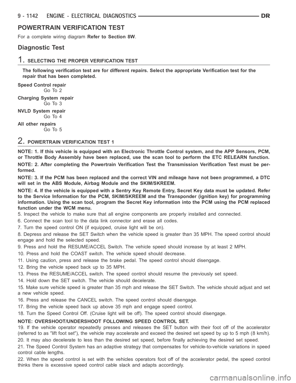
POWERTRAIN VERIFICATION TEST
For a complete wiring diagramRefer to Section 8W.
Diagnostic Test
1.SELECTING THE PROPER VERIFICATION TEST
The following verification test are for different repairs. Select the appropriate Verification test for the
repair that has been completed.
Speed Control repair
Go To 2
Charging System repair
Go To 3
NVLD System repair
Go To 4
All other repairs
Go To 5
2.POWERTRAIN VERIFICATION TEST 1
NOTE: 1. If this vehicle is equipped with an Electronic Throttle Control system, and the APP Sensors, PCM,
or Throttle Body Assembly have been replaced, use the scan tool to perform the ETC RELEARN function.
NOTE: 2. After completing the Powertrain Verification Test the Transmission Verification Test must be per-
formed.
NOTE: 3. If the PCM has been replaced and the correct VIN and mileage have notbeen programmed, a DTC
will set in the ABS Module, Airbag Module and the SKIM/SKREEM.
NOTE: 4. If the vehicle is equipped with a Sentry Key Remote Entry, Secret Key data must be updated. Refer
to the Service Information for the PCM, SKIM/SKREEM and the Transponder (ignition key) for programming
information. Using the scan tool, program the Secret Key information intothe PCM using the PCM replaced
function under the WCM menu.
5. Inspect the vehicle to make sure that all engine components are properlyinstalled and connected.
6. Connect the scan tool to the data link connector and erase all codes.
7. Turn the speed control ON (if equipped, cruise light will be on).
8. Depress and release the SET Switch when the vehicle speed is greater than35 MPH. The speed control should
engage and hold the selected speed.
9. Press and hold the RESUME/ACCEL Switch. The vehicle speed should increase by at least 2 MPH.
10. Press and hold the COAST switch. The vehicle speed should decrease.
11. Using caution, press and release the brake pedal. The speed control should disengage.
12. Bring the vehicle speed back up to 35 MPH.
13. Press the RESUME/ACCEL switch. The speed control should resume the previously set speed.
14. Hold down the SET switch. The vehicle should decelerate.
15. Make sure vehicle speed is greater than 35 mph and release the SET Switch. The vehicle should adjust and set
a new vehicle speed.
16. Press and release the CANCEL switch. The speed control should disengage.
17. Bring the vehicle speed back up above 35 mph and engage speed control.
18. Turn the Speed Control Off. (Cruise light will be off). The speed control should disengage.
NOTE: OVERSHOOT/UNDERSHOOT FOLLOWING SPEED CONTROL SET.
19. If the vehicle operator repeatedly presses and releases the SET buttonwith their foot off of the accelerator
(referred to as
lift foot set), the vehicle may accelerate and exceed the desired set speed by up to 5 mph (8km/h).
20. It may also decelerate to less than the desired set speed, before finally achieving the desired set speed.
21. The Speed Control System has an adaptive strategy that compensates forvehicle-to-vehicle variations in speed
control cable lengths.
22. When the speed control is set with the vehicles operators foot off of theaccelerator pedal, the speed control
thinks there is excessive speed control cable slack and adapts accordingly.