2006 DODGE RAM SRT-10 air filter
[x] Cancel search: air filterPage 3366 of 5267

GEAR RATIOS
The 545RFE gear ratios are:
OPERATION
The 45RFE/545RFE offers full electronic control of all automatic up and downshifts, and features real-time adaptive
closed-loop shift and pressure control. Electronic shift and torque converter clutch controls help protect the trans-
mission from damage due to high temperatures, which can occur under severeoperating conditions. By altering shift
schedules, line pressure, and converter clutch control, these controls reduce heat generation and increase trans-
mission cooling.
To help reduce efficiency-robbing parasitic losses, the transmissions includes a dual-stage transmission fluid pump
with electronic output pressure control. Under most driving conditions,pump output capacity greatly exceeds that
which is needed to keep the clutches applied. The 45RFE/545RFE pump-pressure control system monitors input
torque and adjusts the pump pressure accordingly. The primary stage of thepump works continuously; the second
stage is bypassed when demand is low. The control system also monitors input and output speed and, if incipient
clutch slip is observed, the pressure control solenoid duty cycle is varied, increasing pressure in proportion to
demand.
A high-travel torque converter damper assembly allows earlier torque converter clutch engagement to reduce slip-
page. Needle-type thrust bearings reduce internal friction. The 45RFE/545RFE is packaged in a one-piece die-cast
aluminum case. To reduce NVH, the case has high lateral, vertical and torsional stiffness. It is also designed to
maximize the benefit of the structural dust cover that connects the bottomof the bell housing to the engine bed-
plate, enhancing overall power train stiffness. Dual filters protect thepump and other components. A cooler return
filter is added to the customary main sump filter. Independent lubrication and cooler circuits assure ample pressure
for normal transmission operation even if the cooler is obstructed or the fluid cannot flow due to extremely low
temperatures.
The hydraulic control system design (without electronic assist) provides the transmission with PARK, REVERSE,
NEUTRAL, SECOND, and THIRD gears, based solely on driver shift lever selection. This design allows the vehicle
to be driven (in “limp-in” mode) in the event of a electronic control systemfailure, or a situation that the Transmis-
sion Control Module (TCM) recognizes as potentially damaging to the transmission.
The TCM also performs certain self-diagnostic functions and provides comprehensive information (sensor data,
DTC’s, etc.) which is helpful in proper diagnosis and repair. This information can be viewed with the DRB
scan
tool.
DIAGNOSIS AND TESTING
AUTOMATIC TRANSMISSION
CAUTION: Before attempting any repair on a RFE automatic transmission, check for Diagnostic Trouble
Codes with the scan tool.
Transmission malfunctions may be caused by these general conditions:
Poor engine performance
Page 3382 of 5267
NOTE: Do not use shop towels or rags to dry the case (or any other transmission component) unless they
aremadefromlint-freematerials.Lintwillsticktocasesurfacesandtransmission components and circu-
late throughout the transmission after assembly. A sufficient quantity of lint can block fluid passages and
interfere with valve body operation.
INSPECTION
Inspect the case for cracks, porous spots, worn bores, or damaged threads.Damaged threads can be repaired with
Helicoil
thread inserts. However, the case will have to be replaced if it exhibits any type of damage or wear.
ASSEMBLY
NOTE: Clean and inspect all components. Replace any components which showevidence of excessive wear
or scoring.
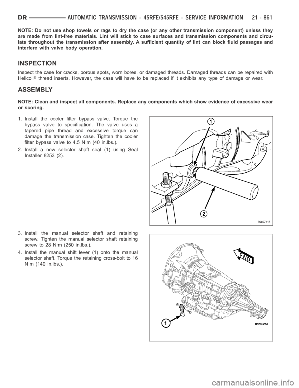
1. Install the cooler filter bypass valve. Torque the
bypass valve to specification. The valve uses a
tapered pipe thread and excessive torque can
damage the transmission case. Tighten the cooler
filter bypass valve to 4.5 Nꞏm (40 in.lbs.).
2. Install a new selector shaft seal (1) using Seal
Installer 8253 (2).
3. Install the manual selector shaft and retaining
screw. Tighten the manual selector shaft retaining
screw to 28 Nꞏm (250 in.lbs.).
4. Install the manual shift lever (1) onto the manual
selector shaft. Torque the retaining cross-bolt to 16
Nꞏm (140 in.lbs.).
Page 3430 of 5267
FLUID AND FILTER
DIAGNOSIS AND TESTING
EFFECTS OF INCORRECT FLUID LEVEL
Alowfluidlevelallowsthepumptotakeinairalongwiththefluid.Airinthe fluid will cause fluid pressures to be
low and develop slower than normal. If the transmission is overfilled, thegears churn the fluid into foam. This aer-
ates the fluid and causing the same conditions occurring with a low level. In either case, air bubbles cause fluid
overheating, oxidation, and varnish buildup which interferes with valveand clutch operation. Foaming also causes
fluid expansion which can result in fluid overflow from the transmission vent or fill tube. Fluid overflow can easily be
mistaken for a leak if inspection is not careful.
CAUSES OF BURNT FLUID
Burnt, discolored fluid is a result of overheating which has three primarycauses.
1. Internal clutch slippage, usually caused by low line pressure, inadequate clutch apply pressure, or clutch seal
failure.
2. A result of restricted fluid flow through the main and/or auxiliary cooler. This condition is usually the result of a
faulty or improperly installed drainback valve, a damaged oil cooler, or severe restrictions in the coolers and lines
caused by debris or kinked lines.
3. Heavy duty operation with a vehicle not properly equipped for this type of operation. Trailer towing or similar high
load operation will overheat the transmission fluid if the vehicle is improperly equipped. Such vehicles should
have an auxiliary transmission fluid cooler, a heavy duty cooling system,and the engine/axle ratio combination
needed to handle heavy loads.
FLUID CONTAMINATION
Transmission fluid contamination is generally a result of:
adding incorrect fluid
failure to clean dipstick and fill tube when checking level
engine coolant entering the fluid
internal failure that generates debris
overheat that generates sludge (fluid breakdown)
failure to replace contaminated converter after repair
The use of non-recommended fluids can result in transmission failure. Theusual results are erratic shifts, slippage,
abnormal wear and eventual failure due to fluid breakdown and sludge formation. Avoid this condition by using rec-
ommended fluids only.
The dipstick cap and fill tube should be wiped clean before checking fluid level. Dirt, grease and other foreign mate-
rial on the cap and tube could fall into the tube if not removed beforehand. Take the time to wipe the cap and tube
clean before withdrawing the dipstick.
Engine coolant in the transmission fluid is generally caused by a cooler malfunction. The only remedy is to replace
the radiator as the cooler in the radiator is not a serviceable part. If coolant has circulated through the transmission,
an overhaul is necessary.
The torque converter should also be replaced whenever a failure generatessludge and debris. This is necessary
because normal converter flushing procedures will not remove all contaminants.
STANDARD PROCEDURE
FLUID LEVEL CHECK
Low fluid level can cause a variety of conditions because it allows the pumpto take in air along with the fluid. As
in any hydraulic system, air bubbles make the fluid spongy, therefore, pressures will be low and build up slowly.
Improper filling can also raise the fluid level too high. When the transmssion has too much fluid, the geartrain
churns up foam and cause the same conditions which occur with a low fluid level.
Page 3501 of 5267
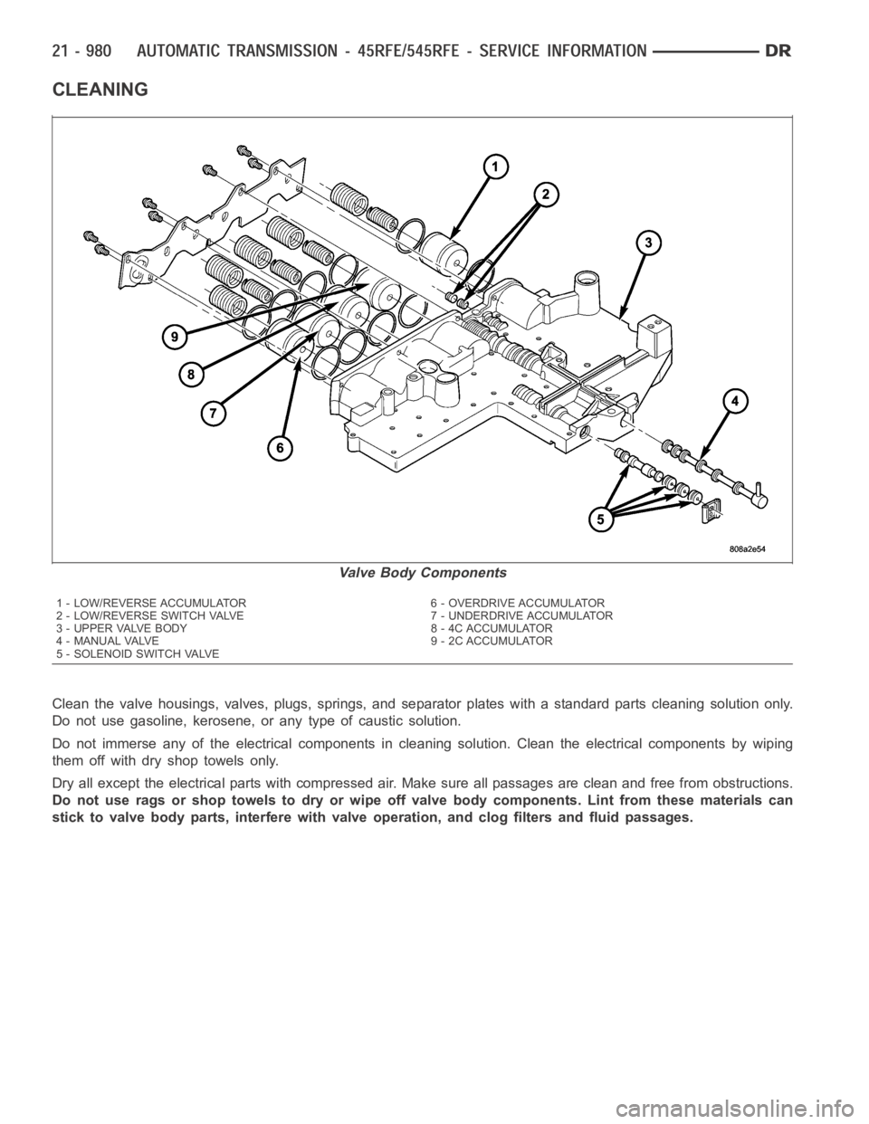
CLEANING
Clean the valve housings, valves, plugs, springs, and separator plates with a standard parts cleaning solution only.
Do not use gasoline, kerosene, or any type of caustic solution.
Do not immerse any of the electrical components in cleaning solution. Clean the electrical components by wiping
them off with dry shop towels only.
Dry all except the electrical parts with compressed air. Make sure all passages are clean and free from obstructions.
Do not use rags or shop towels to dry or wipe off valve body components. Lint from these materials can
stick to valve body parts, interfere with valve operation, and clog filters and fluid passages.
Valve Body Components
1 - LOW/REVERSE ACCUMULATOR 6 - OVERDRIVE ACCUMULATOR
2 - LOW/REVERSE SWITCH VALVE 7 - UNDERDRIVE ACCUMULATOR
3 - UPPER VALVE BODY 8 - 4C ACCUMULATOR
4 - MANUAL VALVE 9 - 2C ACCUMULATOR
5 - SOLENOID SWITCH VALVE
Page 3787 of 5267
page page
AUTOMATIC TRANSMISSION - 48RE - SERVICE
INFORMATION
DESCRIPTION ............................. 1268
OPERATION ............................... 1271
DIAGNOSIS AND TESTING
AUTOMATIC TRANSMISSION .............. 1277
PRELIMINARY ............................ 1277
ROAD TESTING .......................... 1277
HYDRAULIC PRESSURE TEST . ........... 1278
AIR TESTING TRANSMISSION CLUTCH
AND BAND OPERATION................... 1281
CONVERTER HOUSING FLUID LEAK ...... 1282
DIAGNOSIS CHARTS ..................... 1283
STANDARD PROCEDURE - ALUMINUM
THREAD REPAIR ......................... 1293
REMOVAL ................................. 1294
DISASSEMBLY ............................. 1298
CLEANING ................................. 1306
INSPECTION ............................... 1306
ASSEMBLY . ............................... 1307
INSTALLATION ............................. 1317
SCHEMATICS AND DIAGRAMS
HYDRAULIC SCHEMATICS ................ 1322
SPECIFICATIONS
TRANSMISSION .......................... 1336
SPECIAL TOOLS
RE TRANSMISSION ...................... 1339
ACCUMULATOR
DESCRIPTION ............................. 1341
OPERATION ............................... 1342
INSPECTION ............................... 1342
BANDS
DESCRIPTION ............................. 1343
OPERATION ............................... 1343
ADJUSTMENTS
ADJUSTMENT - BANDS ................... 1344
SYSTEM-BRAKE TRANSMISSION SHIFT
INTERLOCK
DESCRIPTION ............................. 1345
OPERATION ............................... 1345
DIAGNOSIS AND TESTING - BRAKE
TRANSMISSION SHIFT INTERLOCK ........ 1345
ADJUSTMENTS - BRAKE TRANSMISSION
SHIFT INTERLOCK ....................... 1345
GOVERNOR-ELECTRONIC
DESCRIPTION ............................. 1347
OPERATION ............................... 1348
REMOVAL ................................. 1349
INSTALLATION ............................. 1350SEAL-EXTENSION HOUSING
REMOVAL ................................. 1352
INSTALLATION ............................. 1352
FLUID AND FILTER
DIAGNOSIS AND TESTING
EFFECTS OF INCORRECT FLUID LEVEL . . . 1353
CAUSES OF BURNT FLUID ............... 1353
FLUID CONTAMINATION .................. 1353
STANDARD PROCEDURE
FLUID LEVEL CHECK ..................... 1353
FLUID AND FILTER REPLACEMENT ....... 1355
TRANSMISSION FILL ..................... 1357
CLUTCH-FRONT
DESCRIPTION ............................. 1358
OPERATION ............................... 1358
DISASSEMBLY . ............................ 1359
INSPECTION............................... 1360
ASSEMBLY................................ 1360
SERVO-FRONT
DESCRIPTION ............................. 1363
OPERATION ............................... 1363
DISASSEMBLY . ............................ 1364
CLEANING ................................. 1364
INSPECTION ............................... 1365
ASSEMBLY................................ 1365
CABLE-GEARSHIFT
DIAGNOSIS AND TESTING - GEARSHIFT
CABLE ................................... 1366
REMOVAL ................................. 1366
INSTALLATION ............................. 1367
ADJUSTMENTS - GEARSHIFT CABLE ........ 1368
PUMP-OIL
DESCRIPTION ............................. 1369
OPERATION ............................... 1369
DISASSEMBLY ............................. 1370
CLEANING ................................. 1371
INSPECTION ............................... 1371
ASSEMBLY................................ 1373
BEARING-OUTPUT SHAFT FRONT
REMOVAL ................................. 1375
INSTALLATION ............................. 1375
BEARING-OUTPUT SHAFT REAR
REMOVAL ................................. 1376
INSTALLATION ............................. 1376
CLUTCH-OVERDRIVE
DESCRIPTION ............................. 1377
OPERATION ............................... 1377
UNIT-OVERDRIVE
REMOVAL ................................. 1378
DISASSEMBLY ............................. 1379
Page 3802 of 5267
3. Lower vehicle.
4. Turn OD switch on.
5. Secure test gauge so it can be viewed from drivers seat.
6. Start engine and shift into D range.
7. Increase vehicle speed gradually until 3-4 shift occurs and note gauge pressure.
8. Pressure should be 524-565 kPa (76-82 psi) with closed throttle and increase to 690-896 kPa (100-130 psi) at
1/2to3/4throttle.Notethatpressurecanincreasetoaround965kPa(140psi) at full throttle.
9. Return to shop or move vehicle off chassis dyno.
PRESSURE TEST ANALYSIS CHART
TEST CONDITION INDICATION
Line pressure OK during any one test Pump and regulator valve OK
Line pressure OK in R but low in D, 2, 1 Leakage in rear clutch area (seal rings, clutch seals)
Pressure low in D Fourth Gear Range Overdrive clutch piston seal, or check ball problem
Pressure OK in 1, 2 but low in D3 and R Leakage in front clutch area
Pressure OK in 2 but low in R and 1 Leakage in rear servo
Front servo pressure in 2 Leakage in servo; broken servo ring or cracked servo
piston
Pressure low in all positions Clogged filter, stuck regulator valve, wornor faulty
pump, low oil level
Governor pressure too high at idle speed Governor pressure solenoid valvesystem fault. Refer
to diagnostic book.
Governor pressure low at all mph figures Faulty governor pressure solenoid, transmission
control module, or governor pressure sensor
Lubrication pressure low at all throttle positions Clogged fluid cooler or lines, seal rings leaking, worn
pump bushings, pump, clutch retainer, or clogged filter.
Line pressure high Output shaft plugged, sticky regulator valve
Line pressure low Sticky regulator valve, clogged filter, worn pump
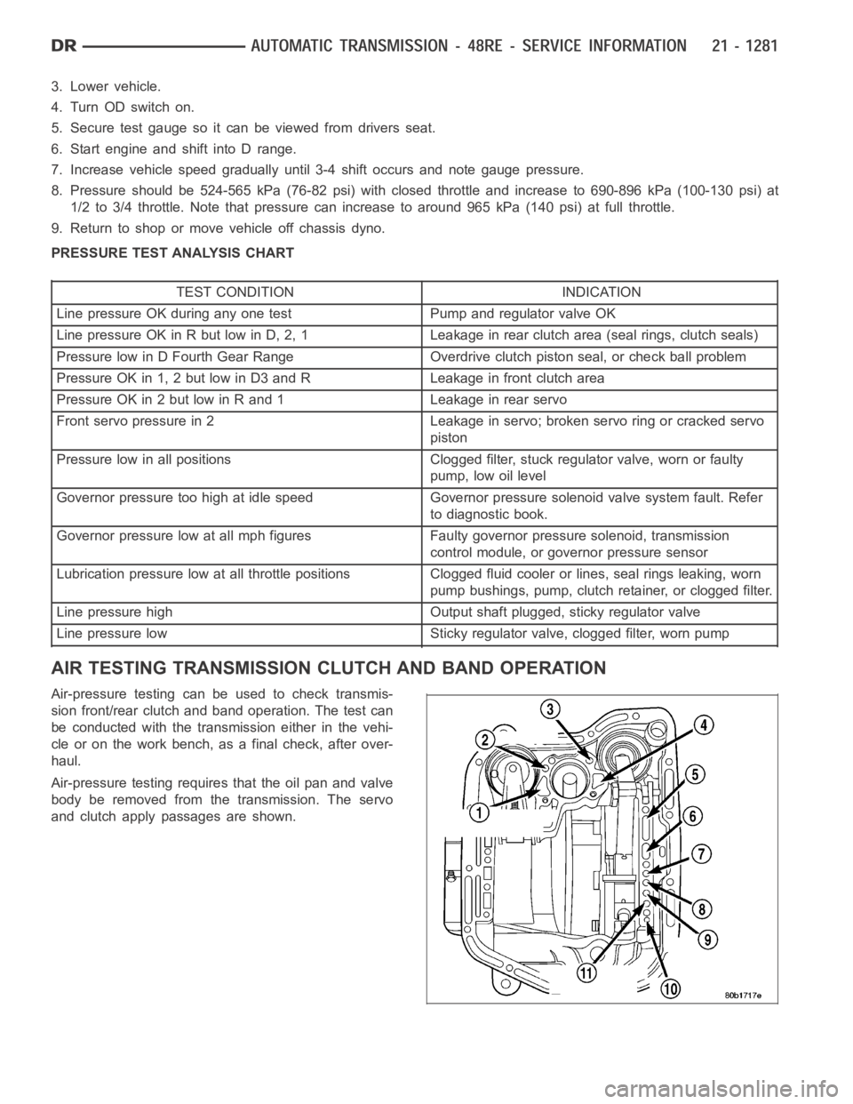
AIR TESTING TRANSMISSION CLUTCH AND BAND OPERATION
Air-pressure testing can be used to check transmis-
sion front/rear clutch and band operation. The test can
be conducted with the transmission either in the vehi-
cle or on the work bench, as a final check, after over-
haul.
Air-pressure testing requires that the oil pan and valve
body be removed from the transmission. The servo
and clutch apply passages are shown.
Page 3805 of 5267
CONDITION POSSIBLE CAUSES CORRECTION
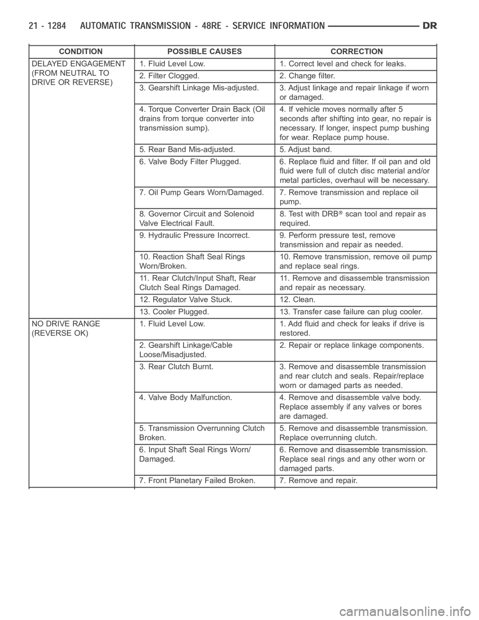
DELAYED ENGAGEMENT
(FROM NEUTRAL TO
DRIVE OR REVERSE)1. Fluid Level Low. 1. Correct level and check for leaks.
2. Filter Clogged. 2. Change filter.
3. Gearshift Linkage Mis-adjusted. 3. Adjust linkage and repair linkage ifworn
or damaged.
4. Torque Converter Drain Back (Oil
drains from torque converter into
transmission sump).4. If vehicle moves normally after 5
seconds after shifting into gear, no repair is
necessary. If longer, inspect pump bushing
for wear. Replace pump house.
5. Rear Band Mis-adjusted. 5. Adjust band.
6. Valve Body Filter Plugged. 6. Replace fluid and filter. If oil pan and old
fluid were full of clutch disc material and/or
metal particles, overhaul will be necessary.
7. Oil Pump Gears Worn/Damaged. 7. Remove transmission and replace oil
pump.
8. Governor Circuit and Solenoid
Valve Electrical Fault.8. Test with DRB
scan tool and repair as
required.
9. Hydraulic Pressure Incorrect. 9. Perform pressure test, remove
transmission and repair as needed.
10. Reaction Shaft Seal Rings
Worn/Broken.10. Remove transmission, remove oil pump
and replace seal rings.
11. Rear Clutch/Input Shaft, Rear
Clutch Seal Rings Damaged.11. Remove and disassemble transmission
and repair as necessary.
12. Regulator Valve Stuck. 12. Clean.
13. Cooler Plugged. 13. Transfer case failure can plug cooler.
NO DRIVE RANGE
(REVERSE OK)1. Fluid Level Low. 1. Add fluid and check for leaks if drive is
restored.
2. Gearshift Linkage/Cable
Loose/Misadjusted.2. Repair or replace linkage components.
3. Rear Clutch Burnt. 3. Removeand disassemble transmission
and rear clutch and seals. Repair/replace
worn or damaged parts as needed.
4. Valve Body Malfunction. 4. Remove and disassemble valve body.
Replace assembly if any valves or bores
are damaged.
5. Transmission Overrunning Clutch
Broken.5. Remove and disassemble transmission.
Replace overrunning clutch.
6. Input Shaft Seal Rings Worn/
Damaged.6. Remove and disassemble transmission.
Replace seal rings and any other worn or
damaged parts.
7. Front Planetary Failed Broken. 7. Remove and repair.
Page 3806 of 5267
CONDITION POSSIBLE CAUSES CORRECTION
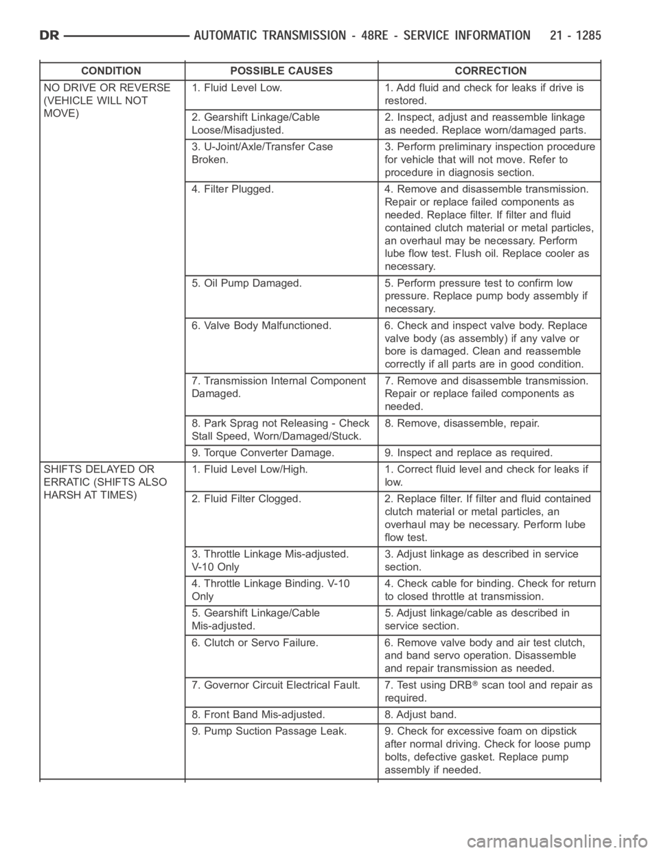
NO DRIVE OR REVERSE
(VEHICLE WILL NOT
MOVE)1. Fluid Level Low. 1. Add fluid and check for leaks if drive is
restored.
2. Gearshift Linkage/Cable
Loose/Misadjusted.2. Inspect, adjust and reassemble linkage
as needed. Replace worn/damaged parts.
3. U-Joint/Axle/Transfer Case
Broken.3. Perform preliminary inspection procedure
for vehicle that will not move. Refer to
procedure in diagnosis section.
4. Filter Plugged. 4. Remove and disassemble transmission.
Repair or replace failed components as
needed. Replace filter. If filter and fluid
contained clutch material or metal particles,
an overhaul may be necessary. Perform
lube flow test. Flush oil. Replace cooler as
necessary.
5. Oil Pump Damaged. 5. Perform pressure test to confirm low
pressure. Replace pump body assembly if
necessary.
6. Valve Body Malfunctioned. 6. Check and inspect valve body. Replace
valve body (as assembly) if any valve or
bore is damaged. Clean and reassemble
correctly if all parts are in good condition.
7. Transmission Internal Component
Damaged.7. Remove and disassemble transmission.
Repair or replace failed components as
needed.
8. Park Sprag not Releasing - Check
Stall Speed, Worn/Damaged/Stuck.8. Remove, disassemble, repair.
9. Torque Converter Damage. 9. Inspect and replace as required.
SHIFTS DELAYED OR
ERRATIC (SHIFTS ALSO
HARSH AT TIMES)1. Fluid Level Low/High. 1. Correct fluid level and check for leaks if
low.
2. Fluid Filter Clogged. 2. Replace filter. If filter and fluid contained
clutch material or metal particles, an
overhaul may be necessary. Perform lube
flow test.
3. Throttle Linkage Mis-adjusted.
V- 1 0 O n l y3. Adjust linkage as described in service
section.
4. Throttle Linkage Binding. V-10
Only4. Check cable for binding. Check for return
to closed throttle at transmission.
5. Gearshift Linkage/Cable
Mis-adjusted.5. Adjust linkage/cable as described in
service section.
6. Clutch or Servo Failure. 6. Remove valve body and air test clutch,
and band servo operation. Disassemble
and repair transmission as needed.
7. Governor Circuit Electrical Fault. 7. Test using DRB
scan tool and repair as
required.
8. Front Band Mis-adjusted. 8. Adjust band.
9. Pump Suction Passage Leak. 9. Check for excessive foam on dipstick
after normal driving. Check for loose pump
bolts, defective gasket. Replace pump
assembly if needed.