2006 DODGE RAM SRT-10 air filter
[x] Cancel search: air filterPage 5184 of 5267
5.7L ENGINE
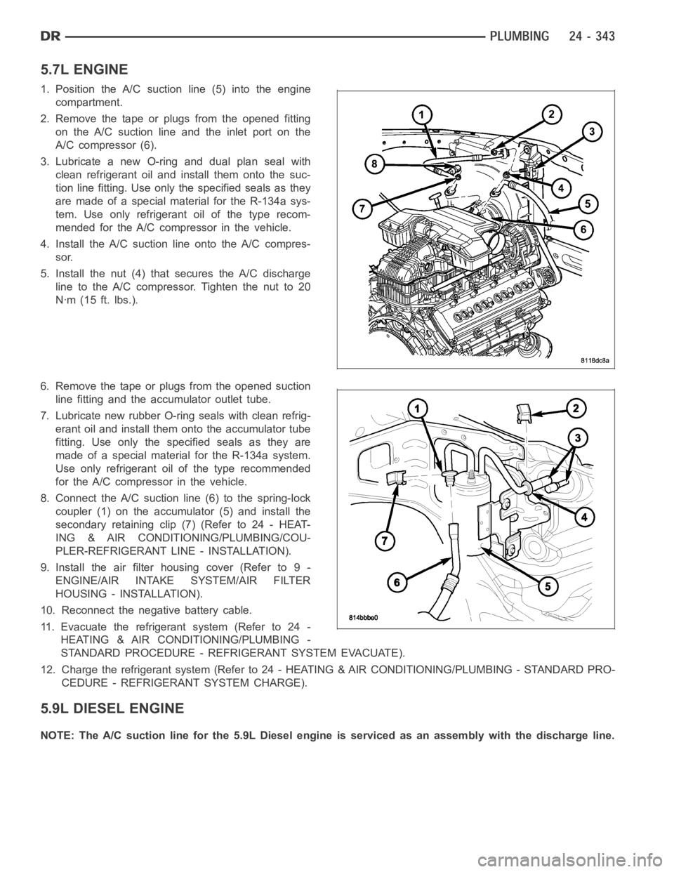
1. Position the A/C suction line (5) into the engine
compartment.
2. Remove the tape or plugs from the opened fitting
on the A/C suction line and the inlet port on the
A/C compressor (6).
3. Lubricate a new O-ring and dual plan seal with
clean refrigerant oil and install them onto the suc-
tion line fitting. Use only the specified seals as they
are made of a special material for the R-134a sys-
tem. Use only refrigerant oil of the type recom-
mended for the A/C compressor in the vehicle.
4. Install the A/C suction line onto the A/C compres-
sor.
5. Install the nut (4) that secures the A/C discharge
line to the A/C compressor. Tighten the nut to 20
Nꞏm (15 ft. lbs.).
6. Remove the tape or plugs from the opened suction
line fitting and the accumulator outlet tube.
7. Lubricate new rubber O-ring seals with clean refrig-
erant oil and install them onto the accumulator tube
fitting. Use only the specified seals as they are
made of a special material for the R-134a system.
Use only refrigerant oil of the type recommended
for the A/C compressor in the vehicle.
8. Connect the A/C suctionline (6) to the spring-lock
coupler (1) on the accumulator (5) and install the
secondary retaining clip (7) (Refer to 24 - HEAT-
ING & AIR CONDITIONING/PLUMBING/COU-
PLER-REFRIGERANT LINE - INSTALLATION).
9. Install the air filter housing cover (Refer to 9 -
ENGINE/AIR INTAKE SYSTEM/AIR FILTER
HOUSING - INSTALLATION).
10. Reconnect the negative battery cable.
11. Evacuate the refrigerant system (Refer to 24 -
HEATING & AIR CONDITIONING/PLUMBING -
STANDARD PROCEDURE - REFRIGERANT SYSTEM EVACUATE).
12. Charge the refrigerant system (Refer to 24 - HEATING & AIR CONDITIONING/PLUMBING - STANDARD PRO-
CEDURE - REFRIGERANT SYSTEM CHARGE).
5.9L DIESEL ENGINE
NOTE: The A/C suction line for the 5.9L Diesel engine is serviced as an assembly with the discharge line.
Page 5185 of 5267
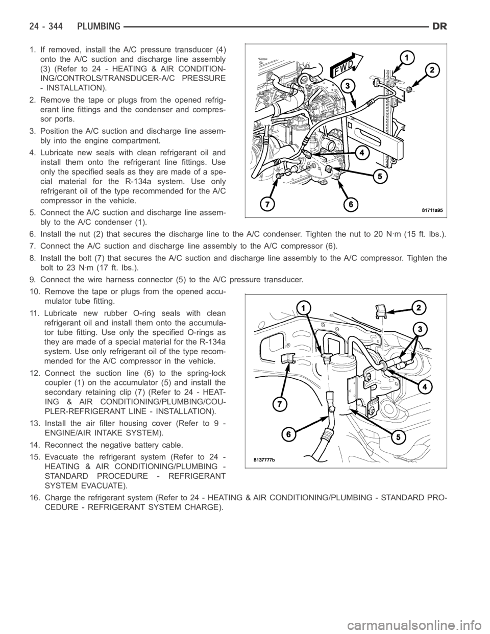
1. If removed, install the A/C pressure transducer (4)
onto the A/C suction and discharge line assembly
(3)(Referto24-HEATING&AIRCONDITION-
ING/CONTROLS/TRANSDUCER-A/C PRESSURE
- INSTALLATION).
2. Remove the tape or plugs from the opened refrig-
erant line fittings and the condenser and compres-
sor ports.
3. Position the A/C suction and discharge line assem-
bly into the engine compartment.
4. Lubricate new seals with clean refrigerant oil and
install them onto the refrigerant line fittings. Use
only the specified seals as they are made of a spe-
cial material for the R-134a system. Use only
refrigerant oil of the type recommended for the A/C
compressor in the vehicle.
5. Connect the A/C suction and discharge line assem-
bly to the A/C condenser (1).
6. Install the nut (2) that secures the discharge line to the A/C condenser.Tighten the nut to 20 Nꞏm (15 ft. lbs.).
7. Connect the A/C suction and discharge line assembly to the A/C compressor(6).
8. Install the bolt (7) that secures the A/C suction and discharge line assembly to the A/C compressor. Tighten the
boltto23Nꞏm(17ft.lbs.).
9. Connect the wire harness connector (5) to the A/C pressure transducer.
10. Remove the tape or plugs from the opened accu-
mulator tube fitting.
11. Lubricate new rubber O-ring seals with clean
refrigerant oil and install them onto the accumula-
tor tube fitting. Use only the specified O-rings as
they are made of a special material for the R-134a
system. Use only refrigerant oil of the type recom-
mended for the A/C compressor in the vehicle.
12. Connect the suction line (6) to the spring-lock
coupler (1) on the accumulator (5) and install the
secondary retaining clip (7) (Refer to 24 - HEAT-
ING & AIR CONDITIONING/PLUMBING/COU-
PLER-REFRIGERANT LINE - INSTALLATION).
13. Install the air filter housing cover (Refer to 9 -
ENGINE/AIR INTAKE SYSTEM).
14. Reconnect the negative battery cable.
15. Evacuate the refrigerant system (Refer to 24 -
HEATING & AIR CONDITIONING/PLUMBING -
STANDARD PROCEDURE - REFRIGERANT
SYSTEM EVACUATE).
16. Charge the refrigerant system (Refer to 24 - HEATING & AIR CONDITIONING/PLUMBING - STANDARD PRO-
CEDURE - REFRIGERANT SYSTEM CHARGE).
Page 5186 of 5267
8.3L ENGINE
1. Remove the tape or plugs from the opened suction
line fitting and the accumulator outlet tube.
2. Lubricate new rubber O-ring seals with clean refrig-
erant oil and install them onto the accumulator tube
fitting. Use only the specified O-rings as they are
made of a special material for the R-134a system.
Use only refrigerant oil of the type recommended
for the A/C compressor in the vehicle.
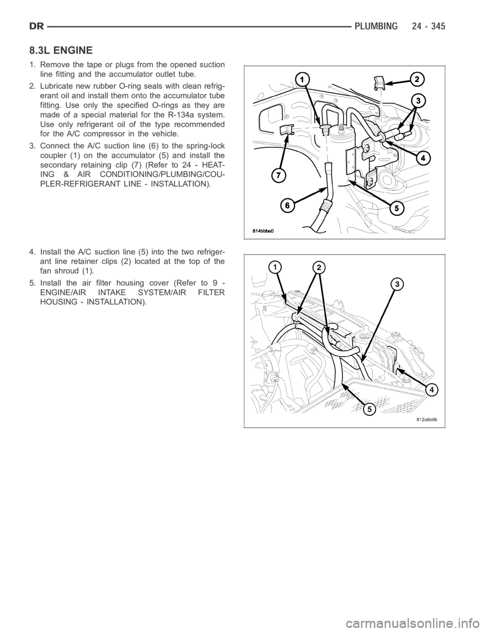
3. Connect the A/C suctionline (6) to the spring-lock
coupler (1) on the accumulator (5) and install the
secondary retaining clip (7) (Refer to 24 - HEAT-
ING & AIR CONDITIONING/PLUMBING/COU-
PLER-REFRIGERANT LINE - INSTALLATION).
4. Install the A/C suction line (5) into the two refriger-
ant line retainer clips (2) located at the top of the
fanshroud(1).
5. Install the air filter housing cover (Refer to 9 -
ENGINE/AIR INTAKE SYSTEM/AIR FILTER
HOUSING - INSTALLATION).
Page 5191 of 5267
TUBE-A/C ORIFICE
DESCRIPTION
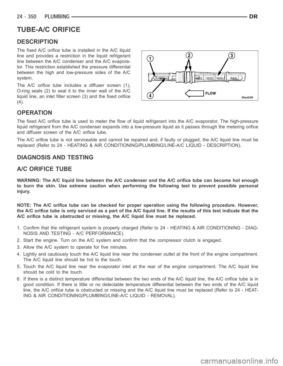
The fixed A/C orifice tube is installed in the A/C liquid
line and provides a restriction in the liquid refrigerant
line between the A/C condenser and the A/C evapora-
tor. This restriction established the pressure differential
between the high and low-pressure sides of the A/C
system.
The A/C orifice tube includes a diffuser screen (1),
O-ring seals (2) to seal it to the inner wall of the A/C
liquid line, an inlet filter screen (3) and the fixed orifice
(4).
OPERATION
The fixed A/C orifice tube is used to meter the flow of liquid refrigerant into the A/C evaporator. The high-pressure
liquid refrigerant from the A/C condenser expands into a low-pressure liquid as it passes through the metering orifice
and diffuser screen of the A/C orifice tube.
The A/C orifice tube is not serviceable and cannot be repaired and, if faulty or plugged, the A/C liquid line must be
replaced (Refer to 24 - HEATING & AIR CONDITIONING/PLUMBING/LINE-A/C LIQUID - DESCRIPTION).
DIAGNOSIS AND TESTING
A/C ORIFICE TUBE
WARNING: The A/C liquid line between the A/C condenser and the A/C orifice tube can become hot enough
to burn the skin. Use extreme caution when performing the following test toprevent possible personal
injury.
NOTE: The A/C orifice tube can be checked for proper operation using the following procedure. However,
the A/C orifice tube is only serviced as a part of the A/C liquid line. If the results of this test indicate that the
A/C orifice tube is obstructed or missing, the A/C liquid line must be replaced.
1. Confirm that the refrigerant system is properly charged (Refer to 24 - HEATING & AIR CONDITIONING - DIAG-
NOSIS AND TESTING - A/C PERFORMANCE).
2. Start the engine. Turn on the A/Csystem and confirm that the compressor clutch is engaged.
3. Allow the A/C system to operate for five minutes.
4. Lightly and cautiously touch the A/C liquid line near the condenser outlet at the front of the engine compartment.
TheA/Cliquidlineshouldbehottothetouch.
5. Touch the A/C liquid line near the evaporator inlet at the rear of the engine compartment. The A/C liquid line
should be cold to the touch.
6. If there is a distinct temperature differential between the two ends of the A/C liquid line, the A/C orifice tube is in
good condition. If there is little or no detectable temperature differential between the two ends of the A/C liquid
line, the A/C orifice tube is obstructed or missing and the A/C liquid line must be replaced (Refer to 24 - HEAT-
ING & AIR CONDITIONING/PLUMBING/LINE-A/C LIQUID - REMOVAL).
Page 5202 of 5267
EXHAUST SYSTEM
The PCM cannot detect a plugged, restricted or leaking exhaust system, although it may set a fuel system fault.
FUEL INJECTOR MECHANICAL MALFUNCTIONS
The PCM cannot determine if a fuel injector is clogged, the needle is sticking or if the wrong injector is installed.
However, these could result in a rich or lean condition causing the PCM to store a diagnostic trouble code for either
misfire, an oxygen sensor, or the fuel system.
EXCESSIVE OIL CONSUMPTION
Although the PCM monitors engine exhaust oxygen content when the system isin closed loop, it cannot determine
excessive oil consumption.
THROTTLE BODY AIR FLOW
The PCM cannot detect a clogged or restricted air cleaner inlet or filter element.
VACUUM ASSIST
The PCM cannot detect leaks or restrictions in the vacuum circuits of vacuum assisted engine control system
devices. However, these could cause the PCM to store a MAP sensor diagnostic trouble code and cause a high idle
condition.
PCM SYSTEM GROUND
The PCM cannot determine a poor system ground. However, one or more diagnostic trouble codes may be gener-
ated as a result of this condition. The module should be mounted to the body at all times, also during diagnostic.
PCM CONNECTOR ENGAGEMENT
The PCM may not be able to determine spread or damaged connector pins. However, it might store diagnostic
trouble codes as a result of spread connector pins.
Page 5207 of 5267
PUMP-LEAK DETECTION
DESCRIPTION
Vehicles equipped with JTEC engine control modules use a leak detection pump. Vehicles equipped with NGC
engine control modules use an NVLD pump. Refer to Natural Vacuum - Leak Detection (NVLD) for additional infor-
mation.
The evaporative emission system is designed to prevent the escape of fuel vapors from the fuel system. Leaks in
the system, even small ones, can allow fuel vapors to escape into the atmosphere. Government regulations require
onboard testing to make sure that the evaporative (EVAP) system is functioning properly. The leak detection system
tests for EVAP system leaks and blockage. It also performs self-diagnostics. During self-diagnostics, the Powertrain
Control Module (PCM) first checks the Leak Detection Pump (LDP) for electrical and mechanical faults. If the first
checks pass, the PCM then uses the LDP to seal the vent valve and pump air intothe system to pressurize it. If a
leak is present, the PCM will continue pumping the LDP to replace the air that leaks out. The PCM determines the
size of the leak based on how fast/long it must pump the LDP as it tries to maintain pressure in the system.
EVAP LEAK DETECTION SYSTEM
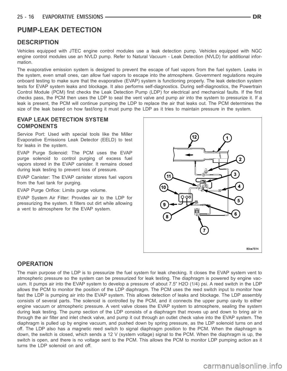
COMPONENTS
Service Port: Used with special tools like the Miller
Evaporative Emissions Leak Detector (EELD) to test
for leaks in the system.
EVAP Purge Solenoid: The PCM uses the EVAP
purge solenoid to control purging of excess fuel
vapors stored in the EVAP canister. It remains closed
during leak testing to prevent loss of pressure.
EVAP Canister: The EVAP canister stores fuel vapors
from the fuel tank for purging.
EVAP Purge Orifice: Limits purge volume.
EVAP System Air Filter: Provides air to the LDP for
pressurizing the system. It filters out dirt while allowing
a vent to atmosphere for the EVAP system.
OPERATION
The main purpose of the LDP is to pressurize the fuel system for leak checking. It closes the EVAP system vent to
atmospheric pressure so the system can be pressurized for leak testing. The diaphragm is powered by engine vac-
uum. It pumps air into the EVAP system to develop a pressure of about 7.5
H2O (1/4) psi. A reed switch in the LDP
allows the PCM to monitor the position of the LDP diaphragm. The PCM uses thereed switch input to monitor how
fast the LDP is pumping air into the EVAP system. This allows detection of leaks and blockage. The LDP assembly
consists of several parts. The solenoid is controlled by the PCM, and it connects the upper pump cavity to either
engine vacuum or atmospheric pressure. A vent valve closes the EVAP systemto atmosphere, sealing the system
during leak testing. The pump section of the LDP consists of a diaphragm that moves up and down to bring air in
through the air filter and inlet check valve, and pump it out through an outlet check valve into the EVAP system. The
diaphragm is pulled up by engine vacuum, and pushed down by spring pressure, as the LDP solenoid turns on and
off. The LDP also has a magnetic reed switch to signal diaphragm position tothe PCM. When the diaphragm is
down, the switch is closed, which sends a 12 V (system voltage) signal to thePCM. When the diaphragm is up, the
switch is open, and there is no voltage sent to the PCM. This allows the PCM tomonitor LDP pumping action as it
turns the LDP solenoid on and off.
Page 5208 of 5267
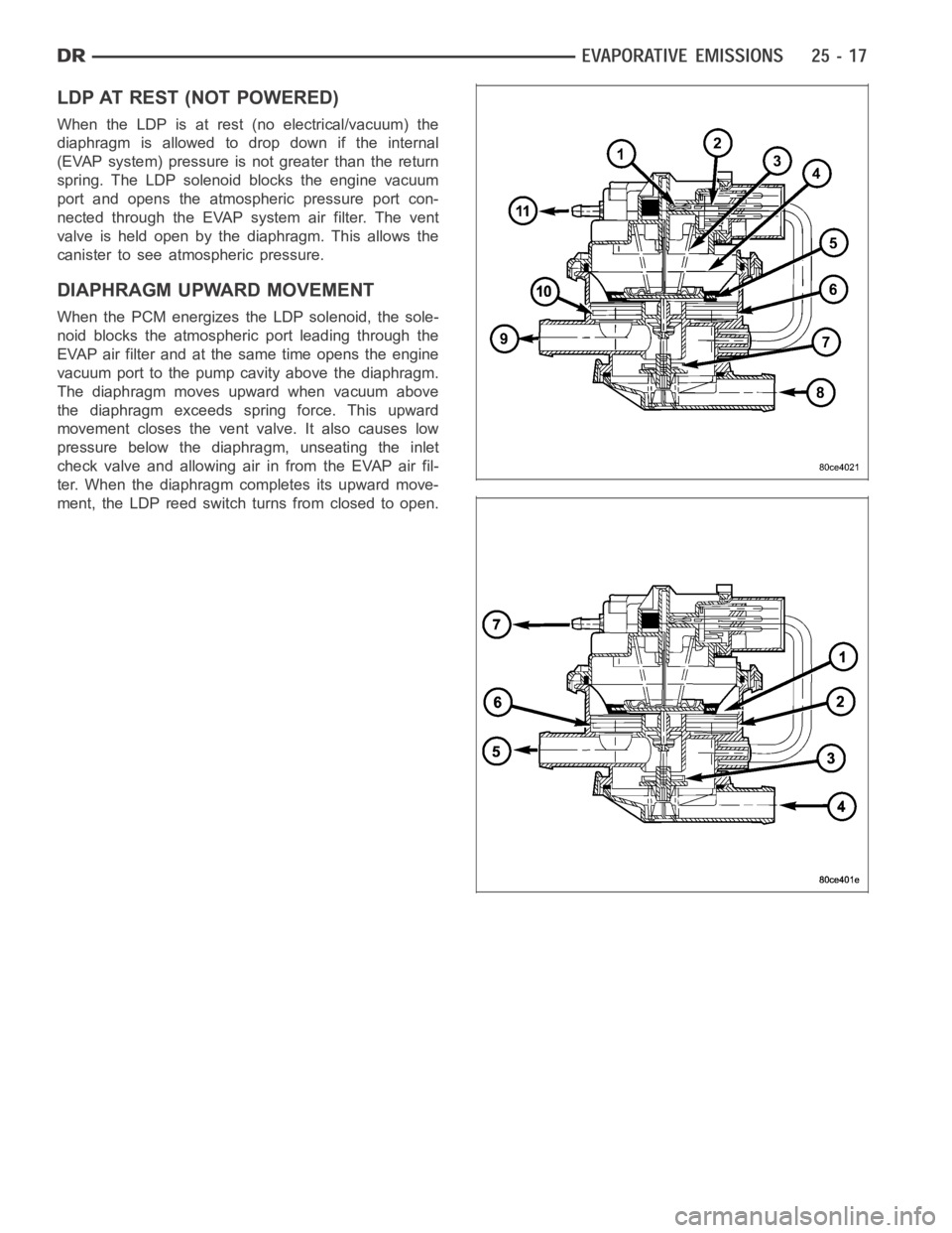
LDP AT REST (NOT POWERED)
When the LDP is at rest (no electrical/vacuum) the
diaphragm is allowed to drop down if the internal
(EVAP system) pressure is not greater than the return
spring. The LDP solenoid blocks the engine vacuum
port and opens the atmospheric pressure port con-
nected through the EVAP system air filter. The vent
valve is held open by the diaphragm. This allows the
canister to see atmospheric pressure.
DIAPHRAGM UPWARD MOVEMENT
When the PCM energizes the LDP solenoid, the sole-
noid blocks the atmospheric port leading through the
EVAP air filter and at the same time opens the engine
vacuum port to the pump cavity above the diaphragm.
The diaphragm moves upward when vacuum above
the diaphragm exceeds spring force. This upward
movement closes the vent valve. It also causes low
pressure below the diaphragm, unseating the inlet
check valve and allowing air in from the EVAP air fil-
ter. When the diaphragm completes its upward move-
ment, the LDP reed switch turns from closed to open.
Page 5209 of 5267
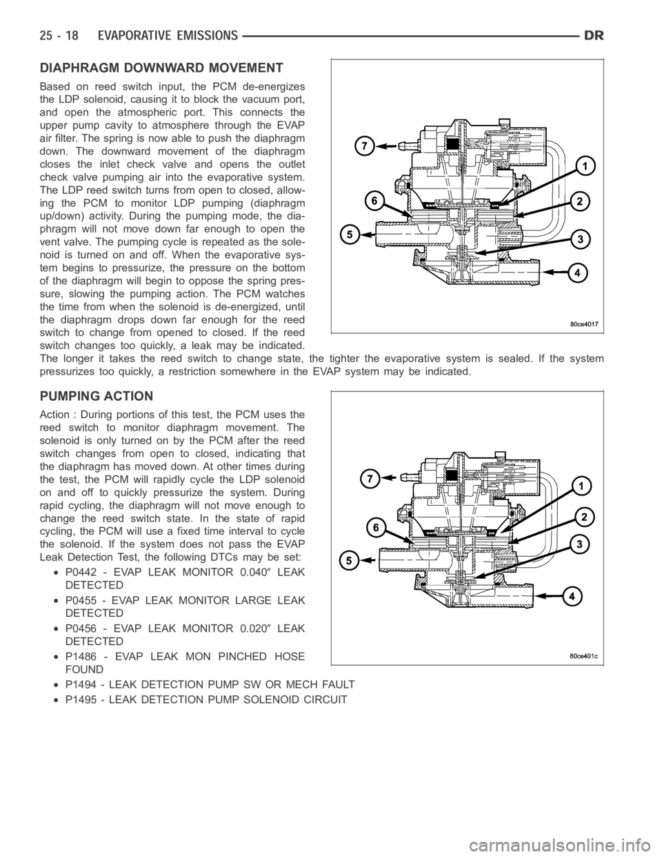
DIAPHRAGM DOWNWARD MOVEMENT
Based on reed switch input, the PCM de-energizes
the LDP solenoid, causing it to block the vacuum port,
and open the atmospheric port. This connects the
upper pump cavity to atmosphere through the EVAP
air filter. The spring is now able to push the diaphragm
down. The downward movement of the diaphragm
closes the inlet check valve and opens the outlet
check valve pumping air into the evaporative system.
The LDP reed switch turns from open to closed, allow-
ing the PCM to monitor LDP pumping (diaphragm
up/down) activity. During the pumping mode, the dia-
phragm will not move down far enough to open the
vent valve. The pumping cycle is repeated as the sole-
noid is turned on and off. When the evaporative sys-
tem begins to pressurize, the pressure on the bottom
of the diaphragm will begin to oppose the spring pres-
sure, slowing the pumping action. The PCM watches
the time from when the solenoid is de-energized, until
the diaphragm drops down far enough for the reed
switch to change from opened to closed. If the reed
switch changes too quickly, a leak may be indicated.
The longer it takes the reed switch to change state, the tighter the evaporative system is sealed. If the system
pressurizes too quickly, a restriction somewhere in the EVAP system may beindicated.
PUMPING ACTION
Action : During portions of this test, the PCM uses the
reed switch to monitor diaphragm movement. The
solenoid is only turned on by the PCM after the reed
switch changes from open to closed, indicating that
the diaphragm has moved down. At other times during
the test, the PCM will rapidly cycle the LDP solenoid
on and off to quickly pressurize the system. During
rapid cycling, the diaphragm will not move enough to
change the reed switch state. In the state of rapid
cycling, the PCM will use a fixed time interval to cycle
the solenoid. If the system does not pass the EVAP
Leak Detection Test, the following DTCs may be set:
P0442 - EVAP LEAK MONITOR 0.040LEAK
DETECTED
P0455 - EVAP LEAK MONITOR LARGE LEAK
DETECTED
P0456 - EVAP LEAK MONITOR 0.020LEAK
DETECTED
P1486 - EVAP LEAK MON PINCHED HOSE
FOUND
P1494 - LEAK DETECTION PUMP SW OR MECH FAULT
P1495 - LEAK DETECTION PUMP SOLENOID CIRCUIT