2006 DODGE RAM SRT-10 air filter
[x] Cancel search: air filterPage 3809 of 5267
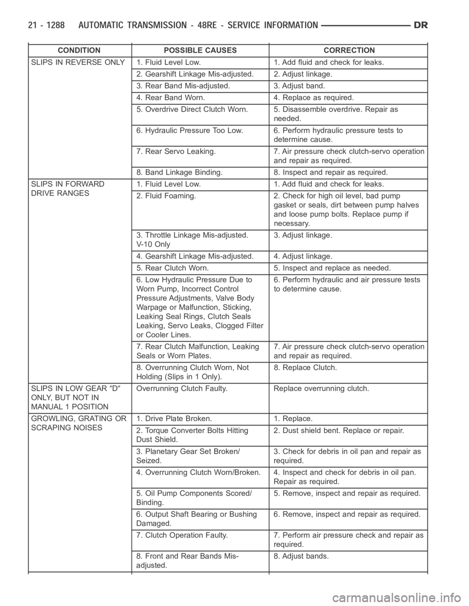
CONDITION POSSIBLE CAUSES CORRECTION
SLIPS IN REVERSE ONLY 1. Fluid Level Low. 1. Add fluid and check for leaks.
2. Gearshift Linkage Mis-adjusted. 2. Adjust linkage.
3. Rear Band Mis-adjusted. 3. Adjust band.
4. Rear Band Worn. 4. Replace as required.
5. Overdrive Direct Clutch Worn. 5. Disassemble overdrive. Repair as
needed.
6. Hydraulic Pressure Too Low. 6. Perform hydraulic pressure tests to
determine cause.
7. Rear Servo Leaking. 7. Air pressure check clutch-servo operation
and repair as required.
8. Band Linkage Binding. 8. Inspect and repair as required.
SLIPS IN FORWARD
DRIVE RANGES1. Fluid Level Low. 1. Add fluid and check for leaks.
2. Fluid Foaming. 2. Check for high oil level, bad pump
gasket or seals, dirt between pump halves
and loose pump bolts. Replace pump if
necessary.
3. Throttle Linkage Mis-adjusted.
V- 1 0 O n l y3. Adjust linkage.
4. Gearshift Linkage Mis-adjusted. 4. Adjust linkage.
5. Rear Clutch Worn. 5. Inspect and replace as needed.
6. Low Hydraulic Pressure Due to
Worn Pump, Incorrect Control
Pressure Adjustments, Valve Body
Warpage or Malfunction, Sticking,
Leaking Seal Rings, Clutch Seals
Leaking, Servo Leaks, Clogged Filter
or Cooler Lines.6. Perform hydraulic and air pressure tests
to determine cause.
7. Rear Clutch Malfunction, Leaking
Seals or Worn Plates.7. Air pressure check clutch-servo operation
and repair as required.
8. Overrunning Clutch Worn, Not
Holding (Slips in 1 Only).8. Replace Clutch.
SLIPS IN LOW GEAR
D
ONLY, BUT NOT IN
MANUAL 1 POSITIONOverrunning Clutch Faulty. Replace overrunning clutch.
GROWLING, GRATING OR
SCRAPING NOISES1. Drive Plate Broken. 1. Replace.
2. Torque Converter Bolts Hitting
Dust Shield.2. Dust shield bent. Replace or repair.
3. Planetary Gear Set Broken/
Seized.3. Check for debris in oil pan and repair as
required.
4. Overrunning Clutch Worn/Broken. 4. Inspect and check for debris in oil pan.
Repair as required.
5. Oil Pump Components Scored/
Binding.5. Remove, inspect and repair as required.
6. Output Shaft Bearing or Bushing
Damaged.6. Remove, inspect and repair as required.
7. Clutch Operation Faulty. 7. Perform air pressure check and repair as
required.
8. Front and Rear Bands Mis-
adjusted.8. Adjust bands.
Page 3872 of 5267
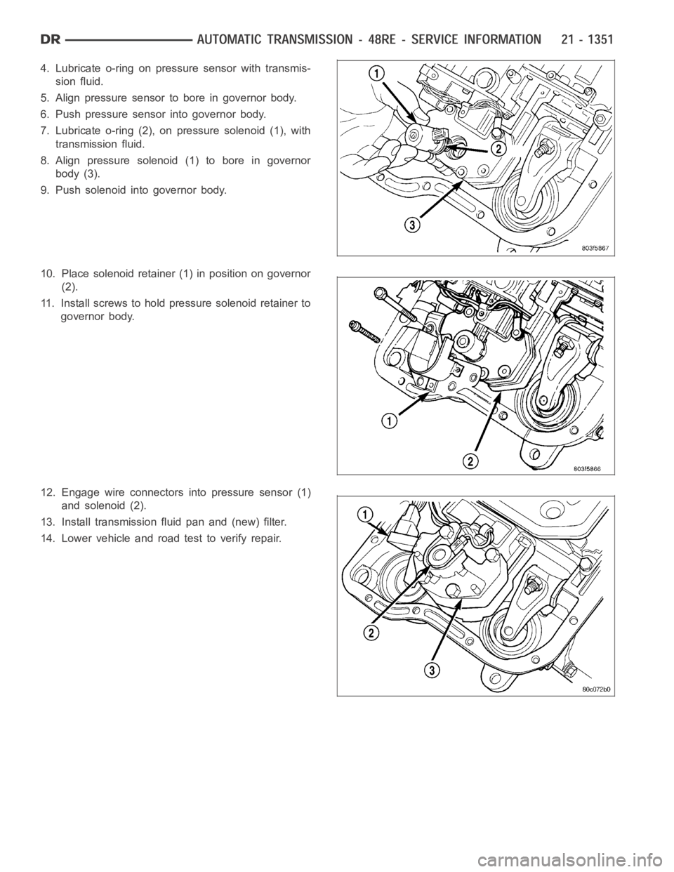
4. Lubricate o-ring on pressure sensor with transmis-
sion fluid.
5. Align pressure sensor to bore in governor body.
6. Push pressure sensor into governor body.
7. Lubricate o-ring (2), on pressure solenoid (1), with
transmission fluid.
8. Align pressure solenoid (1) to bore in governor
body (3).
9. Push solenoid into governor body.
10. Place solenoid retainer (1) in position on governor
(2).
11. Install screws to hold pressure solenoid retainer to
governor body.
12. Engage wire connectors into pressure sensor (1)
and solenoid (2).
13. Install transmission fluid pan and (new) filter.
14. Lower vehicle and road test to verify repair.
Page 3874 of 5267
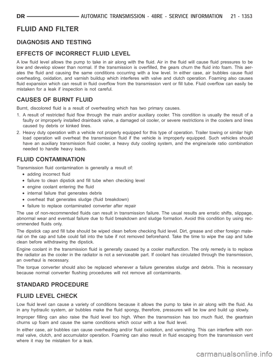
FLUID AND FILTER
DIAGNOSIS AND TESTING
EFFECTS OF INCORRECT FLUID LEVEL
Alowfluidlevelallowsthepumptotakeinairalongwiththefluid.Airinthe fluid will cause fluid pressures to be
low and develop slower than normal. If the transmission is overfilled, thegears churn the fluid into foam. This aer-
ates the fluid and causing the same conditions occurring with a low level. In either case, air bubbles cause fluid
overheating, oxidation, and varnish buildup which interferes with valveand clutch operation. Foaming also causes
fluid expansion which can result in fluid overflow from the transmission vent or fill tube. Fluid overflow can easily be
mistaken for a leak if inspection is not careful.
CAUSES OF BURNT FLUID
Burnt, discolored fluid is a result of overheating which has two primary causes.
1. A result of restricted fluid flow through the main and/or auxiliary cooler. This condition is usually the result of a
faulty or improperly installed drainback valve, a damaged oil cooler, or severe restrictions in the coolers and lines
caused by debris or kinked lines.
2. Heavy duty operation with a vehicle not properly equipped for this type of operation. Trailer towing or similar high
load operation will overheat the transmission fluid if the vehicle is improperly equipped. Such vehicles should
have an auxiliary transmission fluid cooler, a heavy duty cooling system,and the engine/axle ratio combination
needed to handle heavy loads.
FLUID CONTAMINATION
Transmission fluid contamination is generally a result of:
adding incorrect fluid
failure to clean dipstick and fill tube when checking level
engine coolant entering the fluid
internal failure that generates debris
overheat that generates sludge (fluid breakdown)
failure to replace contaminated converter after repair
The use of non-recommended fluids can result in transmission failure. Theusual results are erratic shifts, slippage,
abnormal wear and eventual failure due to fluid breakdown and sludge formation. Avoid this condition by using rec-
ommended fluids only.
The dipstick cap and fill tube should be wiped clean before checking fluid level. Dirt, grease and other foreign mate-
rial on the cap and tube could fall into the tube if not removed beforehand. Take the time to wipe the cap and tube
clean before withdrawing the dipstick.
Engine coolant in the transmission fluid is generally caused by a cooler malfunction. The only remedy is to replace
the radiator as the cooler in the radiator is not a serviceable part. If coolant has circulated through the transmission,
an overhaul is necessary.
The torque converter should also be replaced whenever a failure generatessludge and debris. This is necessary
because normal converter flushing procedures will not remove all contaminants.
STANDARD PROCEDURE
FLUID LEVEL CHECK
Low fluid level can cause a variety of conditions because it allows the pumpto take in air along with the fluid. As
in any hydraulic system, air bubbles make the fluid spongy, therefore, pressures will be low and build up slowly.
Improper filling can also raise the fluid level too high. When the transmssion has too much fluid, the geartrain
churns up foam and cause the same conditions which occur with a low fluid level.
In either case, air bubbles can cause overheating and/or fluid oxidation,and varnishing. This can interfere with nor-
mal valve, clutch, and accumulator operation. Foaming can also result in fluid escaping from the transmission vent
where it may be mistaken for a leak.
Page 3910 of 5267
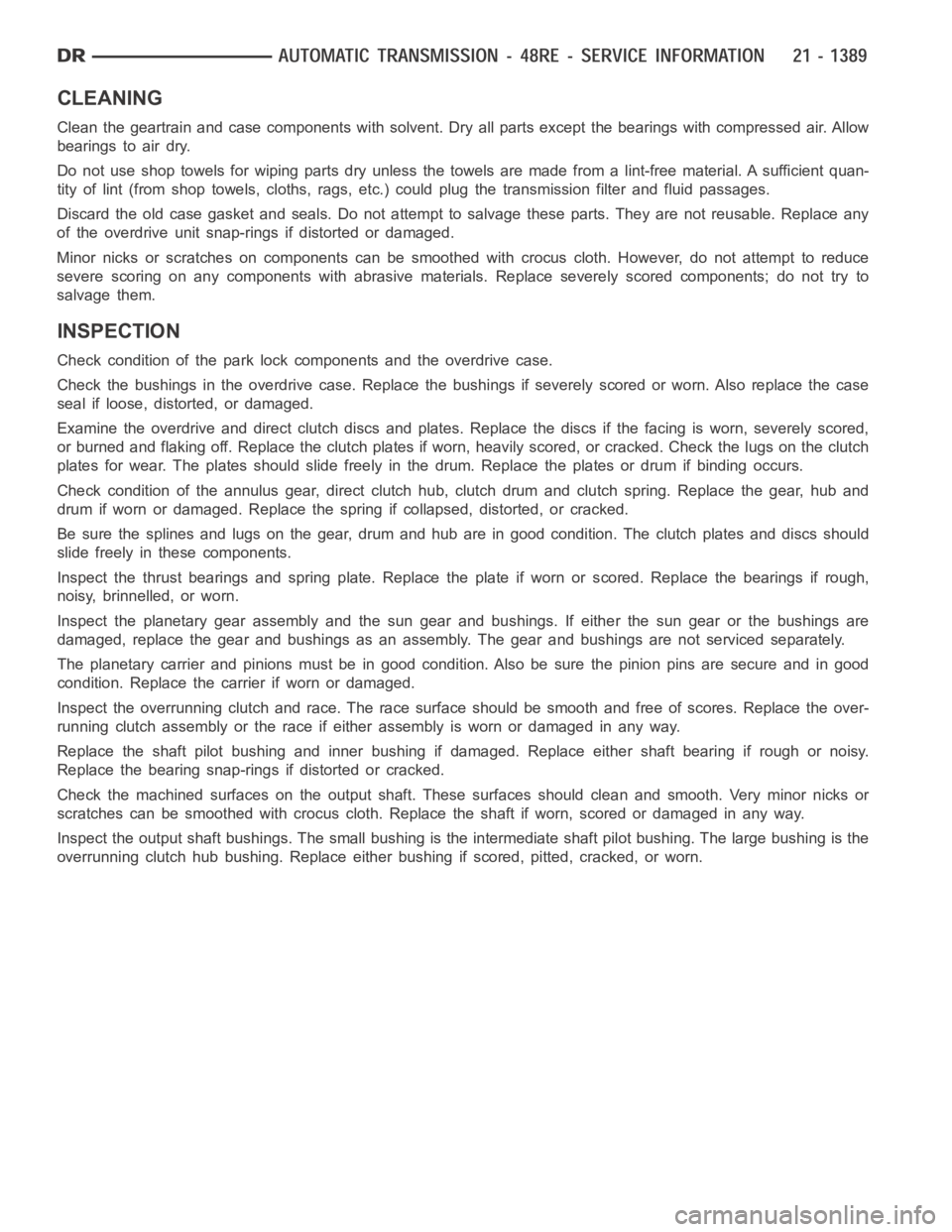
CLEANING
Clean the geartrain and case components with solvent. Dry all parts exceptthebearingswithcompressedair.Allow
bearings to air dry.
Do not use shop towels for wiping parts dry unless the towels are made from a lint-free material. A sufficient quan-
tity of lint (from shop towels, cloths, rags, etc.) could plug the transmission filter and fluid passages.
Discard the old case gasket and seals.Do not attempt to salvage these parts. They are not reusable. Replace any
of the overdrive unit snap-rings if distorted or damaged.
Minor nicks or scratches on components can be smoothed with crocus cloth. However, do not attempt to reduce
severescoringonanycomponentswithabrasive materials. Replace severely scored components; do not try to
salvage them.
INSPECTION
Check condition of the park lock components and the overdrive case.
Check the bushings in the overdrive case. Replace the bushings if severelyscored or worn. Also replace the case
seal if loose, distorted, or damaged.
Examine the overdrive and direct clutch discs and plates. Replace the discs if the facing is worn, severely scored,
or burned and flaking off. Replace the clutch plates if worn, heavily scored, or cracked. Check the lugs on the clutch
plates for wear. The plates should slide freely in the drum. Replace the plates or drum if binding occurs.
Check condition of the annulus gear, direct clutch hub, clutch drum and clutch spring. Replace the gear, hub and
drum if worn or damaged. Replace the spring if collapsed, distorted, or cracked.
Be sure the splines and lugs on the gear, drum and hub are in good condition. The clutch plates and discs should
slide freely in these components.
Inspect the thrust bearings and spring plate. Replace the plate if worn or scored. Replace the bearings if rough,
noisy, brinnelled, or worn.
Inspect the planetary gear assembly and the sun gear and bushings. If either the sun gear or the bushings are
damaged, replace the gear and bushings as an assembly. The gear and bushings are not serviced separately.
The planetary carrier and pinions must be in good condition. Also be sure the pinion pins are secure and in good
condition. Replace the carrier if worn or damaged.
Inspect the overrunning clutch and race. The race surface should be smoothand free of scores. Replace the over-
running clutch assembly or the race if either assembly is worn or damaged inany way.
Replace the shaft pilot bushing and inner bushing if damaged. Replace either shaft bearing if rough or noisy.
Replace the bearing snap-rings if distorted or cracked.
Check the machined surfaces on the output shaft. These surfaces should clean and smooth. Very minor nicks or
scratches can be smoothed with crocus cloth. Replace the shaft if worn, scored or damaged in any way.
Inspect the output shaft bushings. The small bushing is the intermediate shaft pilot bushing. The large bushing is the
overrunning clutch hub bushing. Replace either bushing if scored, pitted, cracked, or worn.
Page 4006 of 5267

4. Remove timing valve cover.
5. Remove 3-4 timing valve and spring.
6. Remove 3-4 quick fill valve, spring and plug.
7. Remove 3-4 shift valve and spring.
8. Remove converter clutch valve, spring and plug.
9. Remove converter clutch timing valve, retainer and
valve spring.
CLEANING
Clean the valve housings, valves, plugs, springs, and separator plates with a standard parts cleaning solution only.
Do not use gasoline, kerosene, or any type of caustic solution.
Do not immerse any of the electrical components in cleaning solution. Clean the governor solenoid and sensor and
the dual solenoid and harness assembly by wiping them off with dry shop towels only.
Dry all except the electrical parts with compressed air. Make sure all passages are clean and free from obstructions.
Do not use rags or shop towels to dry or wipe off valve body components. Lint from these materials can
stick to valve body parts, interfere with valve operation, and clog filters and fluid passages.
Wipe the governor pressure sensor and solenoid valve with dry, lint free shop towels only. The O-rings on the sen-
sor and solenoid valve are the only serviceable components. Be sure the vent ports in the solenoid valve are open
and not blocked by dirt or debris. Replace the valve and/or sensor only whenDRB scan tool diagnosis indicates this
is necessary. Or, if either part has sustained physical damage (dented, deformed, broken, etc.).
CAUTION: Do not turn the small screw at the end of the solenoid valve for any reason. Turning the screw
in either direction will ruin solenoid calibration and result in solenoidfailure. In addition, the filter on the
solenoid valve is NOT serviceable. Do not try to remove the filter as this will damage the valve housing.
INSPECTION
Inspect the throttle and manual valve levers and shafts. Do not attempt to straighten a bent shaft or correct a loose
lever. Replace these components if worn, bent, loose or damaged in any way.
Inspect all of the valve body mating surfaces for scratches, nicks, burrs,or distortion. Use a straightedge to check
surface flatness. Minor scratches may be removed with crocus cloth using only very light pressure.
Minor distortion of a valve body mating surface may be corrected by smoothing the surface with a sheet of crocus
cloth. Position the crocus cloth on a surface plate, sheet of plate glass orequally flat surface. If distortion is severe
or any surfaces are heavily scored, the valve body will have to be replaced.
CAUTION: Many of the valves and plugs, such as the throttle valve, shuttle valve plug, 1-2 shift valve and
1-2 governor plug, are made of coated aluminum. Aluminum components are identified by the dark color of
thespecialcoatingappliedtothesurface(orbytestingwithamagnet).Donot sand aluminum valves or
plugs under any circumstances. This practice could damage the special coating causing the valves/plugs to
stick and bind.
Inspect the valves and plugs for scratches, burrs, nicks, or scores. Minorsurface scratches on steel valves and
plugs can be removed with crocus cloth butdo not round off the edges of the valve or plug lands.Maintaining
Page 4017 of 5267
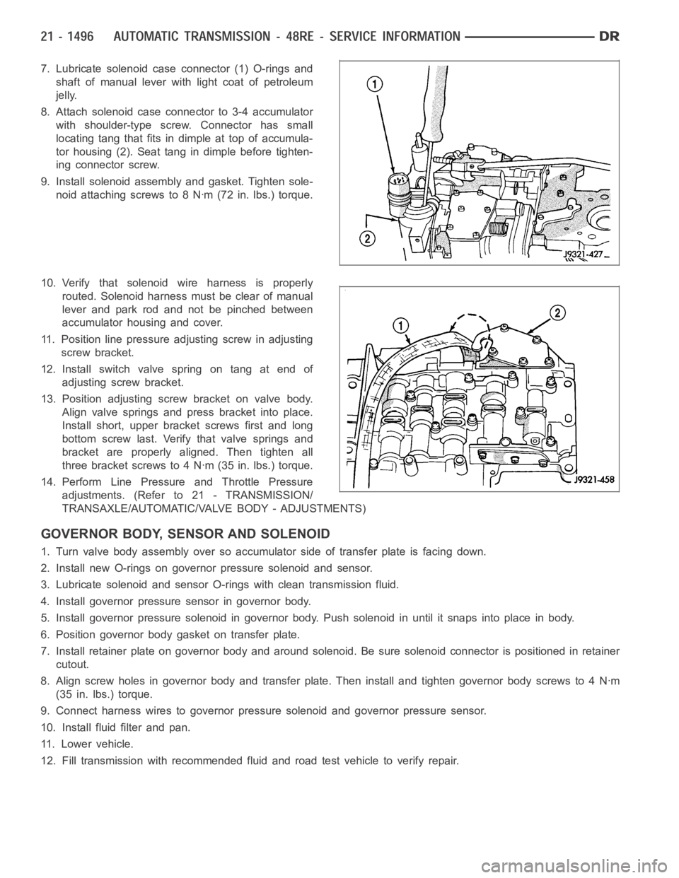
7. Lubricate solenoid case connector (1) O-rings and
shaft of manual lever with light coat of petroleum
jelly.
8. Attach solenoid case connector to 3-4 accumulator
with shoulder-type screw. Connector has small
locating tang that fits indimple at top of accumula-
tor housing (2). Seat tang in dimple before tighten-
ing connector screw.
9. Install solenoid assembly and gasket. Tighten sole-
noid attaching screws to 8 Nꞏm (72 in. lbs.) torque.
10. Verify that solenoid wire harness is properly
routed. Solenoid harness must be clear of manual
lever and park rod and not be pinched between
accumulator housing and cover.
11. Position line pressure adjusting screw in adjusting
screw bracket.
12. Install switch valve spring on tang at end of
adjusting screw bracket.
13. Position adjusting screw bracket on valve body.
Align valve springs and press bracket into place.
Install short, upper bracket screws first and long
bottom screw last. Verify that valve springs and
bracket are properly aligned. Then tighten all
three bracket screws to 4 Nꞏm (35 in. lbs.) torque.
14. Perform Line Pressure and Throttle Pressure
adjustments. (Refer to 21 - TRANSMISSION/
TRANSAXLE/AUTOMATIC/VALVE BODY - ADJUSTMENTS)
GOVERNOR BODY, SENSOR AND SOLENOID
1. Turn valve body assembly over so accumulator side of transfer plate is facing down.
2. Install new O-rings on governor pressure solenoid and sensor.
3. Lubricate solenoid and sensor O-rings with clean transmission fluid.
4. Install governor pressure sensor in governor body.
5. Install governor pressure solenoid in governor body. Push solenoid in until it snaps into place in body.
6. Position governor body gasket on transfer plate.
7. Install retainer plate on governor body and around solenoid. Be sure solenoid connector is positioned in retainer
cutout.
8. Align screw holes in governor body and transfer plate. Then install and tighten governor body screws to 4 Nꞏm
(35 in. lbs.) torque.
9. Connect harness wires to governor pressure solenoid and governor pressure sensor.
10. Install fluid filter and pan.
11. Lower vehicle.
12. Fill transmission with recommended fluid and road test vehicle to verify repair.
Page 4339 of 5267
BODY
WARNING
SAFETY PRECAUTIONS AND WARNINGS
WARNING: Use an OSHA approved breathing filter when spraying paint or solvents in a confined area. Per-
sonal injury can result.
Avoidprolongedskincontactwithpetroleumoralcohol–basedcleaningsolvents. Personal injury can
result.
Do not stand under a hoisted vehicle that is not properly supported on safety stands. Personal injury can
result.
CAUTION: When holes must be drilled or punched in an inner body panel, verify depth of space to the outer
body panel, electrical wiring, or other components. Damage to vehicle canresult.
Do not weld exterior panels unless combustible material on the interior ofvehicle is removed from the
repair area. Fire or hazardous conditions, can result.
Always have a fire extinguisher ready for use when welding.
Disconnect the negative (-) cable clamp from the battery when servicing electrical components that are
live when the ignition is OFF. Damage to electrical system can result.
Do not use abrasive chemicals or compounds on painted surfaces. Damage to finish can result.
Do not use harsh alkaline based cleaning solvents on painted or upholstered surfaces. Damage to finish
or color can result.
Do not hammer or pound on plastic trim panel when servicing interior trim. Plastic panels can break.
DIAGNOSIS AND TESTING
WAT E R L E A K S
Water leaks can be caused by poor sealing, improper body component alignment, body seam porosity, missing
plugs, or blocked drain holes. Centrifugal and gravitational force can cause water to drip from a location away from
the actual leak point, making leak detection difficult. All body sealing points should be water tight in normal wet-
driving conditions. Water flowing downward from the front of the vehicle should not enter the passenger or luggage
compartment. Moving sealing surfaces will not always seal water tight under all conditions. At times, side glass or
door seals will allow water to enter the passenger compartment during highpressure washing or hard driving rain
(severe) conditions. Overcompensating on door or glass adjustments to stop a water leak that occurs under severe
conditions can cause premature sealwear and excessive closing or latching effort. After completing a repair, water
test vehicle to verify leak has stopped before returning vehicle to use.
VISUAL INSPECTION BEFORE WATER LEAK TESTS
Verify that floor and body plugs are in place, body drains are clear, and body components are properly aligned and
sealed. If component alignment or sealing is necessary, refer to the appropriate section of this group for proper
procedures.
WATER LEAK TESTS
WARNING: Do not use electric shop lights or tools in water test area. Personal injury can result.
When the conditions causing a water leak have been determined, simulate the conditions as closely as possible.
Ifaleakoccurswiththevehicleparkedinasteadylightrain,floodtheleak area with an open-ended garden
hose.
If a leak occurs while driving at highway speeds in a steady rain, test the leak area with a reasonable velocity
stream or fan spray of water. Direct the spray in a direction comparable to actual conditions.
If a leak occurs when the vehicle is parked on an incline, hoist the end or sideofthevehicletosimulatethis
condition. This method can be used when the leak occurs when the vehicle accelerates, stops or turns. If the
leak occurs on acceleration, hoist the front of the vehicle. If the leak occurs when braking, hoist the back of the
Page 5133 of 5267
ACCUMULATOR-A/C
DESCRIPTION
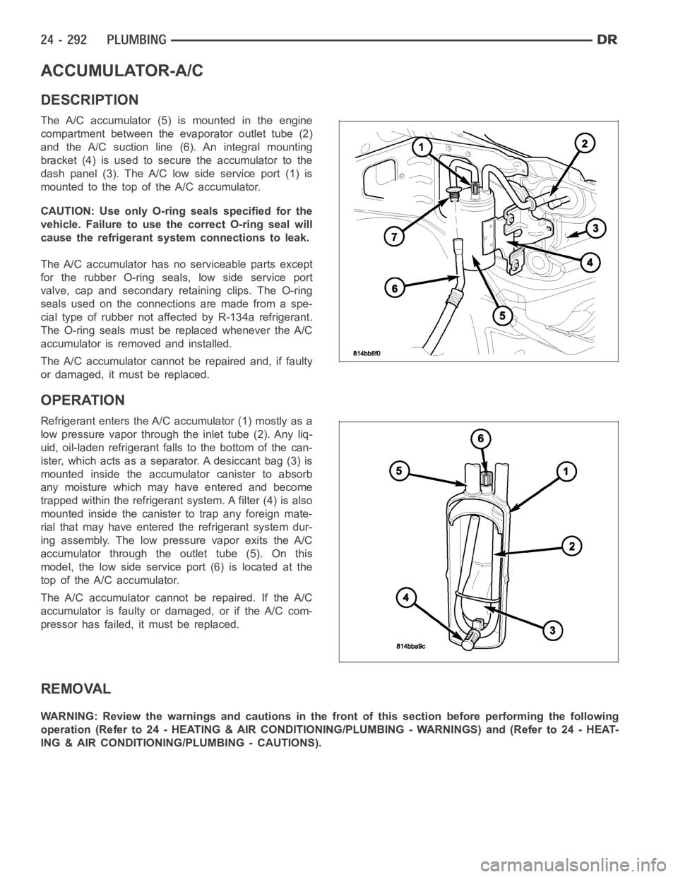
The A/C accumulator (5) is mounted in the engine
compartment between the evaporator outlet tube (2)
and the A/C suction line (6). An integral mounting
bracket (4) is used to secure the accumulator to the
dash panel (3). The A/C low side service port (1) is
mountedtothetopoftheA/Caccumulator.
CAUTION: Use only O-ring seals specified for the
vehicle. Failure to use the correct O-ring seal will
cause the refrigerant system connections to leak.
The A/C accumulator has no serviceable parts except
for the rubber O-ring seals, low side service port
valve, cap and secondary retaining clips. The O-ring
seals used on the connections are made from a spe-
cial type of rubber not affected by R-134a refrigerant.
The O-ring seals must be replaced whenever the A/C
accumulator is removed and installed.
The A/C accumulator cannot be repaired and, if faulty
or damaged, it must be replaced.
OPERATION
Refrigerant enters the A/C accumulator (1) mostly as a
low pressure vapor through the inlet tube (2). Any liq-
uid, oil-laden refrigerant falls to the bottom of the can-
ister, which acts as a separator. A desiccant bag (3) is
mounted inside the accumulator canister to absorb
any moisture which may have entered and become
trapped within the refrigerant system. A filter (4) is also
mounted inside the canister to trap any foreign mate-
rial that may have entered the refrigerant system dur-
ing assembly. The low pressure vapor exits the A/C
accumulator through the outlet tube (5). On this
model, the low side service port (6) is located at the
top of the A/C accumulator.
The A/C accumulator cannot be repaired. If the A/C
accumulator is faulty or damaged, or if the A/C com-
pressor has failed, it must be replaced.
REMOVAL
WARNING: Review the warnings and cautions in the front of this section before performing the following
operation (Refer to 24 - HEATING & AIR CONDITIONING/PLUMBING - WARNINGS) and (Refer to 24 - HEAT-
ING & AIR CONDITIONING/PLUMBING - CAUTIONS).