2006 DODGE RAM SRT-10 air filter
[x] Cancel search: air filterPage 2386 of 5267
OPERATION
High-pressure fuel is supplied from the injection pump, through a high-pressure fuel line, into a fuel rail, through
high-pressure lines, through steel connectors and into the solenoid actuated fuel injector. The ECM actuates the
solenoid causing the needle valve to rise and fuel flows through the spray holes in the nozzle tip into the combus-
tion chamber.
Each fuel injector is connected to the fuel rail by a high-pressure fuel line and a steel connector. This steel con-
nector is positioned into the cylinder head and sealed with an O-ring. The connector is retained in the cylinder head
by a nut (fitting) that is threaded into the cylinder head.
The torquing force of this threaded nut (fitting) provides a sealing pressure between the fuel line connector and the
fuel injector.Retaining nut torque is very critical.If the nut (fitting) is under torqued, the mating surfaces will not
seal and a high-pressure fuel leak will result. If the fitting is over torqued, the connector and injector will deform and
also cause a high-pressure fuel leak. This leak will be inside the cylinderhead and will not be visible. The result will
be a possible fuel injector miss-fire and low power, or a no-start condition.
The fuel injectors use hole type nozzles. High-pressure flows into the side of the injector, the ECM activates the
solenoid causing the injector needle to lift and fuel to be injected. The clearances in the nozzle bore are extremely
small and any dirt or contaminants will cause the injector to stick. Because of this, it is very important to do a
thorough cleaning of any lines before opening up any fuel system component. Always cover or cap any open fuel
connections before a fuel system repair is performed.
Each fuel injector connector tube contains an edge filter that is designedto break up small contaminants before
entering the fuel injector.The edge filters are not a substitute for proper cleaning and covering of allfuel
system components during repair.
The bottom of each fuel injector is sealed to the cylinder head with a1.5mmthick copper shim (gasket). The correct
thickness shim must always be re-installed after removing an injector.
Fuel pressure in the injector circuit decreases after injection. The injector needle valve is immediately closed and
fuel flow into the combustion chamber is stopped. Exhaust gases are prevented from entering the injector nozzle by
the needle valve.
REMOVAL
CAUTION: Refer to Cleaning Fuel System Parts.
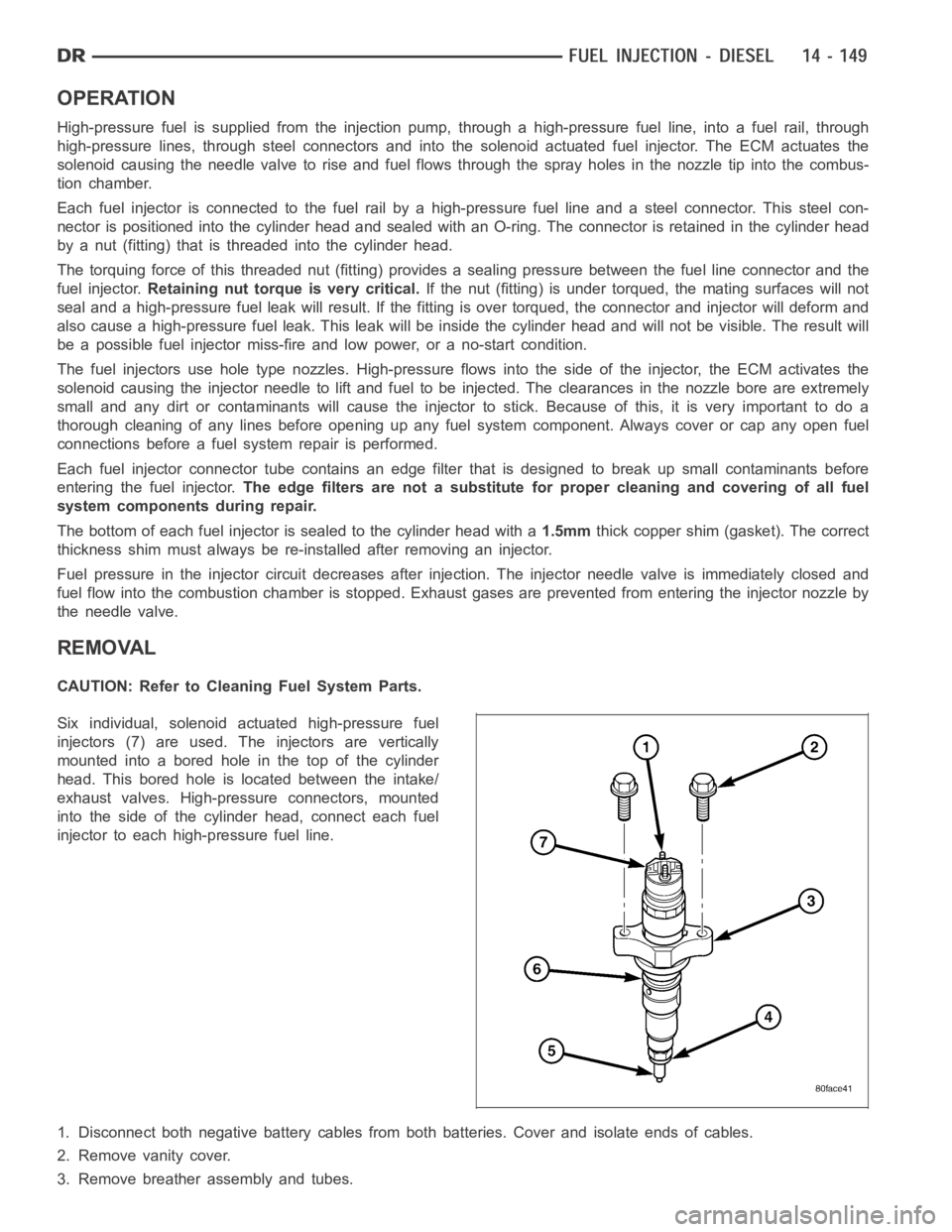
Six individual, solenoid actuated high-pressure fuel
injectors (7) are used. The injectors are vertically
mounted into a bored hole in the top of the cylinder
head. This bored hole is located between the intake/
exhaust valves. High-pressure connectors, mounted
into the side of the cylinder head, connect each fuel
injector to each high-pressure fuel line.
1. Disconnect both negative battery cables from both batteries. Cover andisolate ends of cables.
2. Remove vanity cover.
3. Remove breather assembly and tubes.
Page 2394 of 5267
SENSOR-TEMPERATURE/PRESSURE-INTAKE
DESCRIPTION
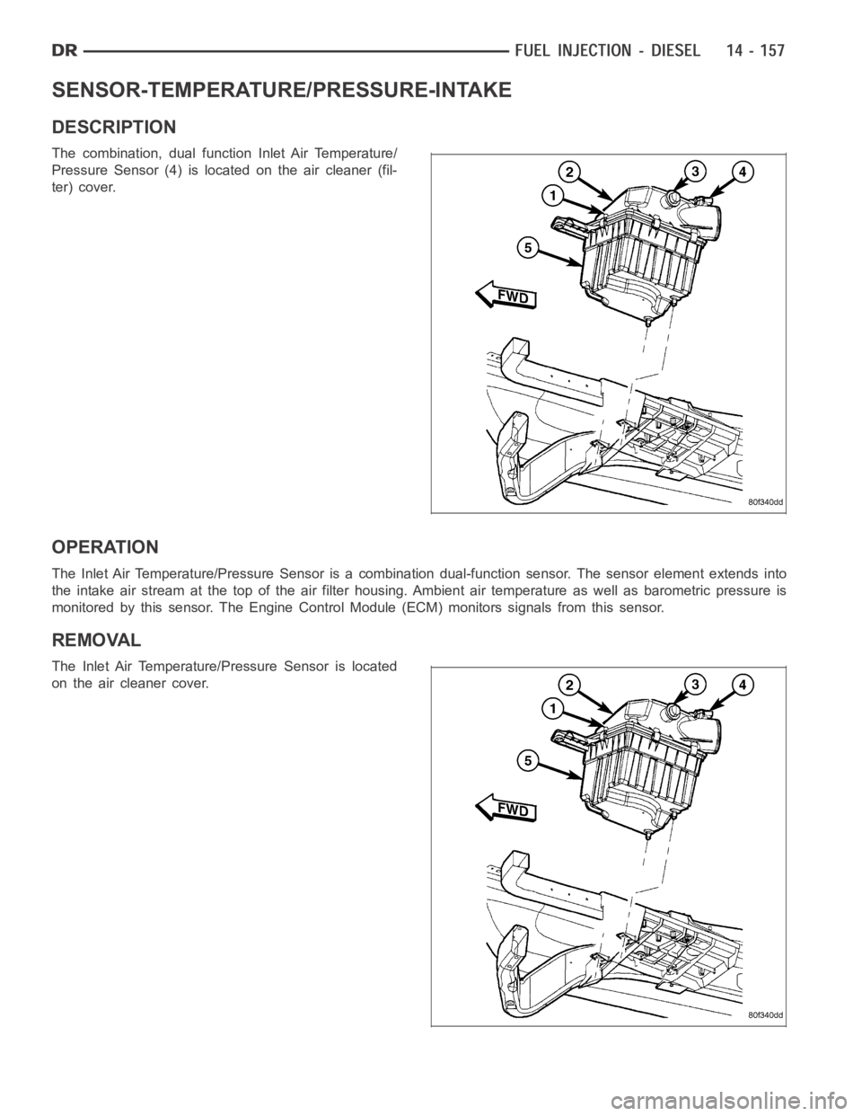
The combination, dual function Inlet Air Temperature/
Pressure Sensor (4) is located on the air cleaner (fil-
ter) cover.
OPERATION
The Inlet Air Temperature/Pressure Sensor is a combination dual-function sensor. The sensor element extends into
the intake air stream at the top of the air filter housing. Ambient air temperature as well as barometric pressure is
monitored by this sensor. The Engine Control Module (ECM) monitors signals from this sensor.
REMOVAL
The Inlet Air Temperature/Pressure Sensor is located
on the air cleaner cover.
Page 2398 of 5267
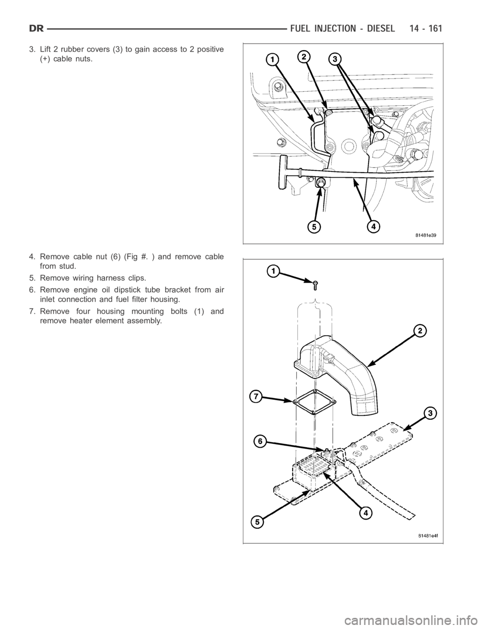
3. Lift 2 rubber covers (3) to gain access to 2 positive
(+) cable nuts.
4. Remove cable nut (6) (Fig #. ) and remove cable
from stud.
5. Remove wiring harness clips.
6. Remove engine oil dipstick tube bracket from air
inlet connection and fuel filter housing.
7. Remove four housing mounting bolts (1) and
remove heater element assembly.
Page 2818 of 5267
5.CHECK FOR A PLUGGED TRANSMISSION OIL FILTER
Turn the ignition off to the lock position.
Remove and inspect the Transmission Oil Pan for excessive debris per the Service Information.
Remove and inspect the Transmission Oil Filter per the Service Information.
Does the Oil Pan contain excessive debris and/or is the Transmission Oil Filter plugged?
Ye s>>
Repair as necessary. If the Transmission Oil Filter is plugged or there is excessive debris, refer to the
Service Information for the proper Hydraulic repair procedure.
Perform 42RLE TRANSMISSION VERIFICATION TEST - VER 1. (Refer to 21 - TRANSMISSION/
TRANSAXLE/AUTOMATIC - 42RLE - STANDARD PROCEDURE)
No>>
Repair internal transmission and inspect the Transmission Oil Pump per the Service Information and
replace if necessary.
Perform 42RLE TRANSMISSION VERIFICATION TEST - VER 1. (Refer to 21 - TRANSMISSION/
TRANSAXLE/AUTOMATIC - 42RLE - STANDARD PROCEDURE)
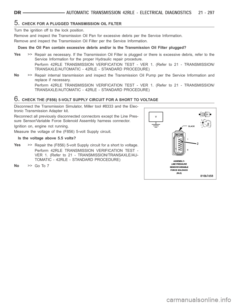
6.CHECK THE (F856) 5-VOLT SUPPLY CIRCUIT FOR A SHORT TO VOLTAGE
Disconnect the Transmission Simulator, Miller tool #8333 and the Elec-
tronic Transmission Adapter kit.
Reconnect all previously disconnected connectors except the Line Pres-
sure Sensor/Variable Force Solenoid Assembly harness connector.
Ignition on, engine not running.
Measure the voltage of the (F856) 5-volt Supply circuit.
Is the voltage above 5.5 volts?
Ye s>>
Repair the (F856) 5-volt Supply circuit for a short to voltage.
Perform 42RLE TRANSMISSION VERIFICATION TEST -
VER 1. (Refer to 21 - TRANSMISSION/TRANSAXLE/AU-
TOMATIC - 42RLE - STANDARD PROCEDURE)
No>>
Go To 7
Page 2865 of 5267
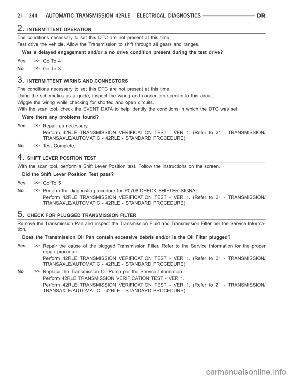
2.INTERMITTENT OPERATION
The conditions necessary to set this DTC are not present at this time.
Test drive the vehicle. Allow the Transmission to shift through all gears and ranges.
Was a delayed engagement and/or a no drive condition present during the testdrive?
Ye s>>
Go To 4
No>>
Go To 3
3.INTERMITTENT WIRING AND CONNECTORS
The conditions necessary to set this DTC are not present at this time.
Using the schematics as a guide, inspect the wiring and connectors specifictothiscircuit.
Wiggle the wiring while checking for shorted and open circuits.
With the scan tool, check the EVENT DATAto help identify the conditions in which the DTC was set.
Were there any problems found?
Ye s>>
Repair as necessary.
Perform 42RLE TRANSMISSION VERIFICATION TEST - VER 1. (Refer to 21 - TRANSMISSION/
TRANSAXLE/AUTOMATIC - 42RLE - STANDARD PROCEDURE)
No>>
Te s t C o m p l e t e .
4.SHIFT LEVER POSITION TEST
With the scan tool, perform a Shift Lever Position test. Follow the instructions on the screen.
Did the Shift Lever Position Test pass?
Ye s>>
Go To 5
No>>
Perform the diagnostic procedure for P0706-CHECK SHIFTER SIGNAL.
Perform 42RLE TRANSMISSION VERIFICATION TEST - VER 1. (Refer to 21 - TRANSMISSION/
TRANSAXLE/AUTOMATIC - 42RLE - STANDARD PROCEDURE)
5.CHECK FOR PLUGGED TRANSMISSION FILTER
Remove the Transmission Pan and inspect the Transmission Fluid and Transmission Filter per the Service Informa-
tion.
Does the Transmission Oil Pan contain excessive debris and/or is the Oil Filter plugged?
Ye s>>
Repair the cause of the plugged Transmission Filter. Refer to the Service Information for the proper
repair procedure.
Perform 42RLE TRANSMISSION VERIFICATION TEST - VER 1. (Refer to 21 - TRANSMISSION/
TRANSAXLE/AUTOMATIC - 42RLE - STANDARD PROCEDURE)
No>>
Replace the Transmission Oil Pump per the Service Information.
Perform 42RLE TRANSMISSION VERIFICATION TEST - VER 1.
Perform 42RLE TRANSMISSION VERIFICATION TEST - VER 1. (Refer to 21 - TRANSMISSION/
TRANSAXLE/AUTOMATIC - 42RLE - STANDARD PROCEDURE)
Page 2910 of 5267
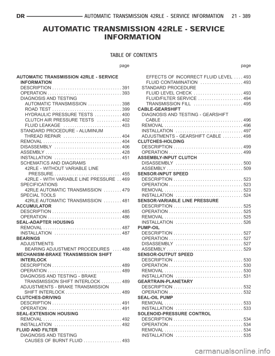
page page
AUTOMATIC TRANSMISSION 42RLE - SERVICE
INFORMATION
DESCRIPTION ............................... 391
OPERATION ................................. 393
DIAGNOSIS AND TESTING
AUTOMATIC TRANSMISSION ............... 398
ROAD TEST ............................... 399
HYDRAULIC PRESSURE TESTS............ 400
CLUTCH AIR PRESSURE TESTS........... 402
FLUID LEAKAGE.......................... 403
STANDARD PROCEDURE - ALUMINUM
THREAD REPAIR .......................... 404
REMOVAL ................................... 404
DISASSEMBLY .............................. 406
ASSEMBLY .................................. 428
INSTALLATION .............................. 451
SCHEMATICS AND DIAGRAMS
42RLE - WITHOUT VARIABLE LINE
PRESSURE............................... 455
42RLE - WITH VARIABLE LINE PRESSURE . . 469
SPECIFICATIONS
42RLE AUTOMATIC TRANSMISSION ........ 479
SPECIAL TOOLS
42RLE AUTOMATIC TRANSMISSION ........ 481
ACCUMULATOR
DESCRIPTION ............................... 485
OPERATION ................................. 486
SEAL-ADAPTER HOUSING
REMOVAL ................................... 487
INSTALLATION .............................. 487
BEARINGS
ADJUSTMENTS
BEARING ADJUSTMENT PROCEDURES.... 488
MECHANISM-BRAKE TRANSMISSION SHIFT
INTERLOCK
DESCRIPTION ............................... 489
OPERATION ................................. 489
DIAGNOSIS AND TESTING - BRAKE
TRANSMISSION SHIFT INTERLOCK ......... 489
ADJUSTMENTS - BRAKE TRANSMISSION
SHIFT INTERLOCK ......................... 489
CLUTCHES-DRIVING
DESCRIPTION ............................... 491
OPERATION ................................. 491
SEAL-EXTENSION HOUSING
REMOVAL ................................... 492
INSTALLATION .............................. 492
FLUID AND FILTER
DIAGNOSIS AND TESTING
CAUSES OF BURNT FLUID ................. 493EFFECTS OF INCORRECT FLUID LEVEL . . . . 493
FLUID CONTAMINATION ................... 493
STANDARD PROCEDURE
FLUID LEVEL CHECK...................... 493
FLUID/FILTER SERVICE .................... 494
TRANSMISSION FILL ...................... 495
CABLE-GEARSHIFT
DIAGNOSIS AND TESTING - GEARSHIFT
CABLE .................................... 496
REMOVAL ................................... 496
INSTALLATION .............................. 497
ADJUSTMENTS - GEARSHIFT CABLE ......... 498
CLUTCHES-HOLDING
DESCRIPTION ............................... 499
OPERATION ................................. 499
ASSEMBLY-INPUT CLUTCH
DISASSEMBLY .............................. 500
ASSEMBLY .................................. 509
SENSOR-INPUT SPEED
DESCRIPTION ............................... 523
OPERATION ................................. 523
REMOVAL ................................... 523
INSTALLATION .............................. 524
SENSOR-VARIABLE LINE PRESSURE
DESCRIPTION ............................... 525
OPERATION ................................. 525
REMOVAL ................................... 525
INSTALLATION .............................. 526
PUMP-OIL
DESCRIPTION ............................... 527
OPERATION ................................. 527
DISASSEMBLY .............................. 527
ASSEMBLY .................................. 529
SENSOR-OUTPUT SPEED
DESCRIPTION ............................... 530
OPERATION ................................. 530
REMOVAL ................................... 530
INSTALLATION .............................. 531
GEARTRAIN-PLANETARY
DESCRIPTION ............................... 532
OPERATION ................................. 532
SEAL-OIL PUMP
REMOVAL ................................... 533
INSTALLATION .............................. 533
SOLENOID-PRESSURE CONTROL
DESCRIPTION ............................... 534
OPERATION ................................. 534
REMOVAL ................................... 534
INSTALLATION .............................. 535
Page 3014 of 5267
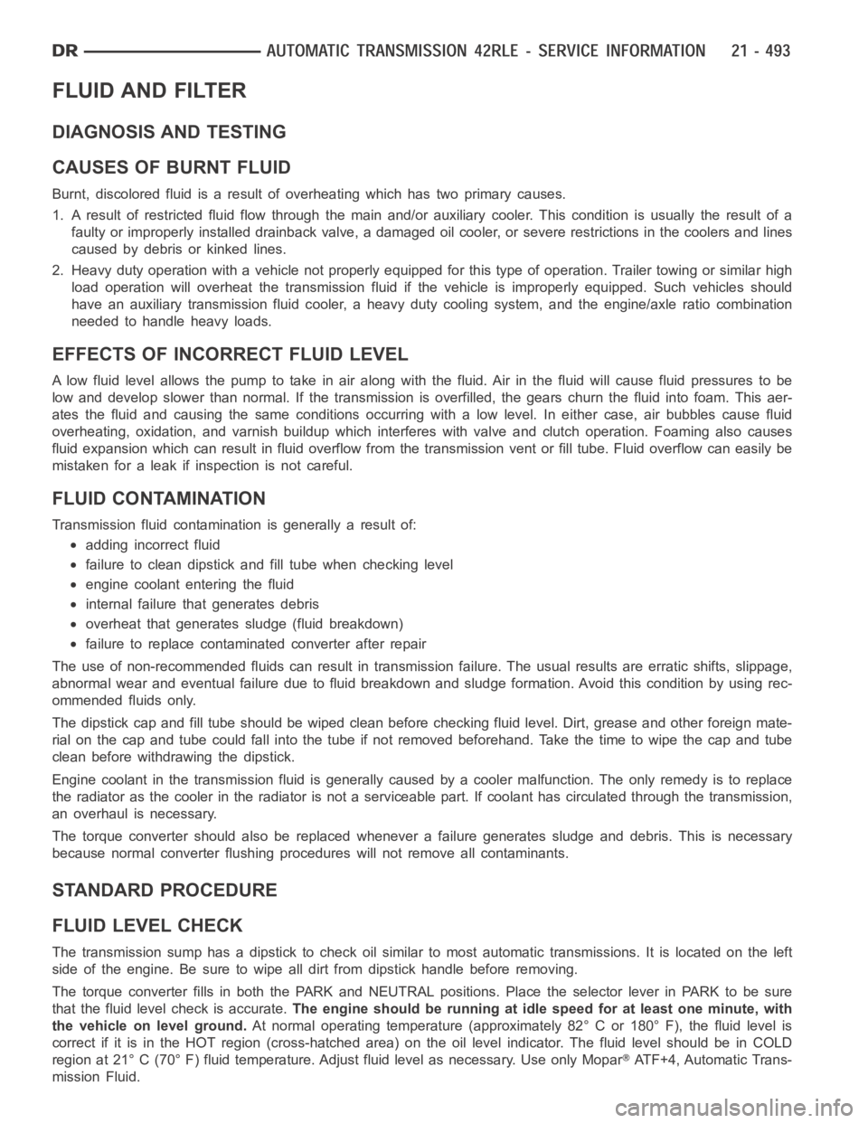
FLUID AND FILTER
DIAGNOSIS AND TESTING
CAUSES OF BURNT FLUID
Burnt, discolored fluid is a result of overheating which has two primary causes.
1. A result of restricted fluid flow through the main and/or auxiliary cooler. This condition is usually the result of a
faulty or improperly installed drainback valve, a damaged oil cooler, or severe restrictions in the coolers and lines
caused by debris or kinked lines.
2. Heavy duty operation with a vehicle not properly equipped for this type of operation. Trailer towing or similar high
load operation will overheat the transmission fluid if the vehicle is improperly equipped. Such vehicles should
have an auxiliary transmission fluid cooler, a heavy duty cooling system,and the engine/axle ratio combination
needed to handle heavy loads.
EFFECTS OF INCORRECT FLUID LEVEL
Alowfluidlevelallowsthepumptotakeinairalongwiththefluid.Airinthe fluid will cause fluid pressures to be
low and develop slower than normal. If the transmission is overfilled, thegears churn the fluid into foam. This aer-
ates the fluid and causing the same conditions occurring with a low level. In either case, air bubbles cause fluid
overheating, oxidation, and varnish buildup which interferes with valveand clutch operation. Foaming also causes
fluid expansion which can result in fluid overflow from the transmission vent or fill tube. Fluid overflow can easily be
mistaken for a leak if inspection is not careful.
FLUID CONTAMINATION
Transmission fluid contamination is generally a result of:
adding incorrect fluid
failure to clean dipstick and fill tube when checking level
engine coolant entering the fluid
internal failure that generates debris
overheat that generates sludge (fluid breakdown)
failure to replace contaminated converter after repair
The use of non-recommended fluids can result in transmission failure. Theusual results are erratic shifts, slippage,
abnormal wear and eventual failure due to fluid breakdown and sludge formation. Avoid this condition by using rec-
ommended fluids only.
The dipstick cap and fill tube should be wiped clean before checking fluid level. Dirt, grease and other foreign mate-
rial on the cap and tube could fall into the tube if not removed beforehand. Take the time to wipe the cap and tube
clean before withdrawing the dipstick.
Engine coolant in the transmission fluid is generally caused by a cooler malfunction. The only remedy is to replace
the radiator as the cooler in the radiator is not a serviceable part. If coolant has circulated through the transmission,
an overhaul is necessary.
The torque converter should also be replaced whenever a failure generatessludge and debris. This is necessary
because normal converter flushing procedures will not remove all contaminants.
STANDARD PROCEDURE
FLUID LEVEL CHECK
The transmission sump has a dipstick to check oil similar to most automatictransmissions. It is located on the left
side of the engine. Be sure to wipe all dirt from dipstick handle before removing.
The torque converter fills in both the PARK and NEUTRAL positions. Place the selector lever in PARK to be sure
that the fluid level check is accurate.The engine should be running at idle speed for at least one minute, with
the vehicle on level ground.At normal operating temperature (approximately 82° C or 180° F), the fluidlevel is
correct if it is in the HOT region (cross-hatched area) on the oil level indicator. The fluid level should be in COLD
region at 21° C (70° F) fluid temperature. Adjust fluid level as necessary.Use only Mopar
ATF+4, Automatic Trans-
mission Fluid.
Page 3150 of 5267
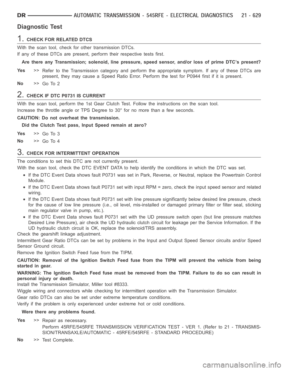
Diagnostic Test
1.CHECKFORRELATEDDTCS
With the scan tool, check for other transmission DTCs.
If any of these DTCs are present, perform their respective tests first.
Are there any Transmission; solenoid, line pressure, speed sensor, and/or loss of prime DTC’s present?
Ye s>>
Refer to the Transmission category and perform the appropriate symptom. If any of these DTCs are
present, they may cause a Speed Ratio Error. Perform the test for P0944 firstifitispresent.
No>>
Go To 2
2.CHECK IF DTC P0731 IS CURRENT
With the scan tool, perform the 1st Gear Clutch Test. Follow the instructions on the scan tool.
Increase the throttle angle or TPS Degree to 30° for no more than a few seconds.
CAUTION: Do not overheat the transmission.
Did the Clutch Test pass, Input Speed remain at zero?
Ye s>>
Go To 3
No>>
Go To 4
3.CHECK FOR INTERMITTENT OPERATION
The conditions to set this DTC are not currently present.
With the scan tool, check the DTC EVENT DATA to help identify the conditionsin which the DTC was set.
If the DTC Event Data shows fault P0731 was set in Park, Reverse, or Neutral,replace the Powertrain Control
Module.
If the DTC Event Data shows fault P0731 set with input RPM = zero, check the input speed sensor and related
wiring.
If the DTC Event Data shows fault P0731 set with line pressure significantly below desired line pressure, check
for the cause of low line pressure (i.e., oil level, mis-installed or damaged primary filter or filter seal, sticking
main regulator valve in pump, etc.).
If the DTC Event Data shows fault P0731 set with the UD pressure switch open (but line pressure matches
Desired Line Pressure), air check the UD hydraulic clutch circuit for leakage per the Service Information. If the
UD hydraulic clutch circuit is OK, replace the solenoid/TRS assembly.
Check the gearshift linkage adjustment.
Intermittent Gear Ratio DTCs can be set by problems in the Input and Output Speed Sensor circuits and/or Speed
Sensor Ground circuit.
Remove the Ignition Switch Feed fuse from the TIPM.
CAUTION: Removal of the Ignition Switch Feed fuse from the TIPM will prevent the vehicle from being
startedingear.
WARNING: The Ignition Switch Feed fuse must be removed from the TIPM. Failure to do so can result in
personal injury or death.
Install the Transmission Simulator, Miller tool #8333.
Wiggle wiring and connectors while checking for intermittent operation with the Transmission Simulator.
Gear ratio DTCs can also be set under extreme temperature conditions.
Verify if the problem is only experienced under extreme hot or cold conditions.
Were there any problems found.
Ye s>>
Repair as necessary.
Perform 45RFE/545RFE TRANSMISSION VERIFICATION TEST - VER 1. (Refer to 21- TRANSMIS-
SION/TRANSAXLE/AUTOMATIC - 45RFE/545RFE - STANDARD PROCEDURE)
No>>
Te s t C o m p l e t e .