2006 DODGE RAM SRT-10 air filter
[x] Cancel search: air filterPage 1788 of 5267
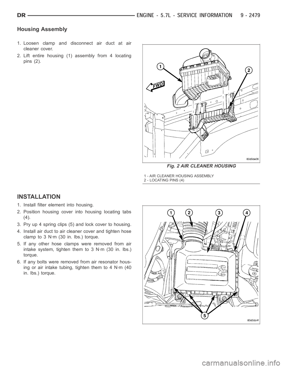
Housing Assembly
1. Loosen clamp and disconnect air duct at air
cleaner cover.
2. Lift entire housing (1) assembly from 4 locating
pins (2).
INSTALLATION
1. Install filter element into housing.
2. Position housing cover into housing locating tabs
(4).
3. Pry up 4 spring clips (5) and lock cover to housing.
4. Install air duct to air cleaner cover and tighten hose
clamp to 3 Nꞏm (30 in. lbs.) torque.
5. If any other hose clamps were removed from air
intake system, tighten them to 3 Nꞏm (30 in. lbs.)
torque.
6. If any bolts were removed from air resonator hous-
ing or air intake tubing, tighten them to 4 Nꞏm (40
in. lbs.) torque.
Fig. 2 AIR CLEANER HOUSING
1 - AIR CLEANER HOUSING ASSEMBLY
2 - LOCATING PINS (4)
Page 1824 of 5267
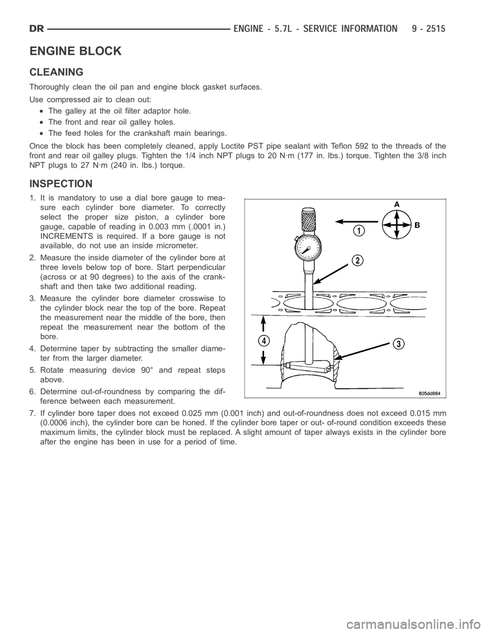
ENGINE BLOCK
CLEANING
Thoroughly clean the oil pan and engine block gasket surfaces.
Use compressed air to clean out:
The galley at the oil filter adaptor hole.
The front and rear oil galley holes.
The feed holes for the crankshaft main bearings.
Once the block has been completely cleaned, apply Loctite PST pipe sealantwith Teflon 592 to the threads of the
front and rear oil galley plugs. Tighten the 1/4 inch NPT plugs to 20 Nꞏm (177in. lbs.) torque. Tighten the 3/8 inch
NPT plugs to 27 Nꞏm (240 in. lbs.) torque.
INSPECTION
1. It is mandatory to use a dial bore gauge to mea-
sure each cylinder bore diameter. To correctly
select the proper size piston, a cylinder bore
gauge, capable of reading in 0.003 mm (.0001 in.)
INCREMENTS is required. If a bore gauge is not
available, do not use an inside micrometer.
2. Measure the inside diameter of the cylinder bore at
three levels below top of bore. Start perpendicular
(across or at 90 degrees) to the axis of the crank-
shaft and then take two additional reading.
3. Measure the cylinder bore diameter crosswise to
the cylinder block near the top of the bore. Repeat
the measurement near the middle of the bore, then
repeat the measurement near the bottom of the
bore.
4. Determine taper by subtracting the smaller diame-
ter from the larger diameter.
5. Rotate measuring device 90° and repeat steps
above.
6. Determine out-of-roundness by comparing the dif-
ference between each measurement.
7. If cylinder bore taper does not exceed 0.025 mm (0.001 inch) and out-of-roundness does not exceed 0.015 mm
(0.0006 inch), the cylinder bore can be honed. If the cylinder bore taper orout- of-round condition exceeds these
maximum limits, the cylinder block must be replaced. A slight amount of taper always exists in the cylinder bore
after the engine has been in use for a period of time.
Page 1848 of 5267
SEAL - CRANKSHAFT OIL - REAR
DIAGNOSIS AND TESTING - REAR SEAL AREA LEAKS
Since it is sometimes difficult to determine the source of an oil leak in therear seal area of the engine, a more
involved inspection is necessary. The following steps should be followedto help pinpoint the source of the leak.
If the leakage occurs at the crankshaft rear oil seal area:
1. Disconnect the battery.
2. Raise the vehicle.
3. Remove torque converter or clutch housing cover and inspect rear of block for evidence of oil. Use a black light
to check for the oil leak:
a. Circular spray pattern generally indicates seal leakage or crankshaftdamage.
b. Where leakage tends to run straight down, possible causes are a porous block, camshaft bore cup plugs, oil
galley pipe plugs, oil filter runoff, and main bearing cap to cylinder block mating surfaces. See Engine, for
proper repair procedures of these items.
4. If no leaks are detected, pressurized the crankcase as outlined in the section, Inspection (Engine oil Leaks in
general)
CAUTION: Do not exceed 20.6 kPa (3 psi).
5. If the leak is not detected, very slowly turn the crankshaft and watch forleakage. If a leak is detected between
the crankshaft and seal while slowly turning the crankshaft, it is possible the crankshaft seal surface is damaged.
The seal area on the crankshaft could have minor nicks or scratches that canbe polished out with emery cloth.
CAUTION: Use extreme caution when crankshaft polishing is necessary to remove minor nicks or
scratches. The crankshaft seal flange is specially machined to complement the function of the rear oil seal.
6. For bubbles that remain steady with shaft rotation, no further inspection can be done until disassembled. (Refer
to 9 - ENGINE - DIAGNOSIS AND TESTING), under the Oil Leak row, for components inspections on possible
causes and corrections.
7. After the oil leak root cause and appropriate corrective action have been identified, (Refer to 9 - ENGINE/EN-
GINE BLOCK/CRANKSHAFT OIL SEAL - REAR - REMOVAL).
REMOVAL
NOTE: This procedure can be performed in vehi-
cle.
1. If being performed in vehicle, remove the transmis-
sion.
2. Remove the flexplate (Refer to 9 - ENGINE/EN-
GINE BLOCK/FLEX PLATE - REMOVAL).
NOTE: The crankshaft oil seal CAN NOT be reused
after removal.
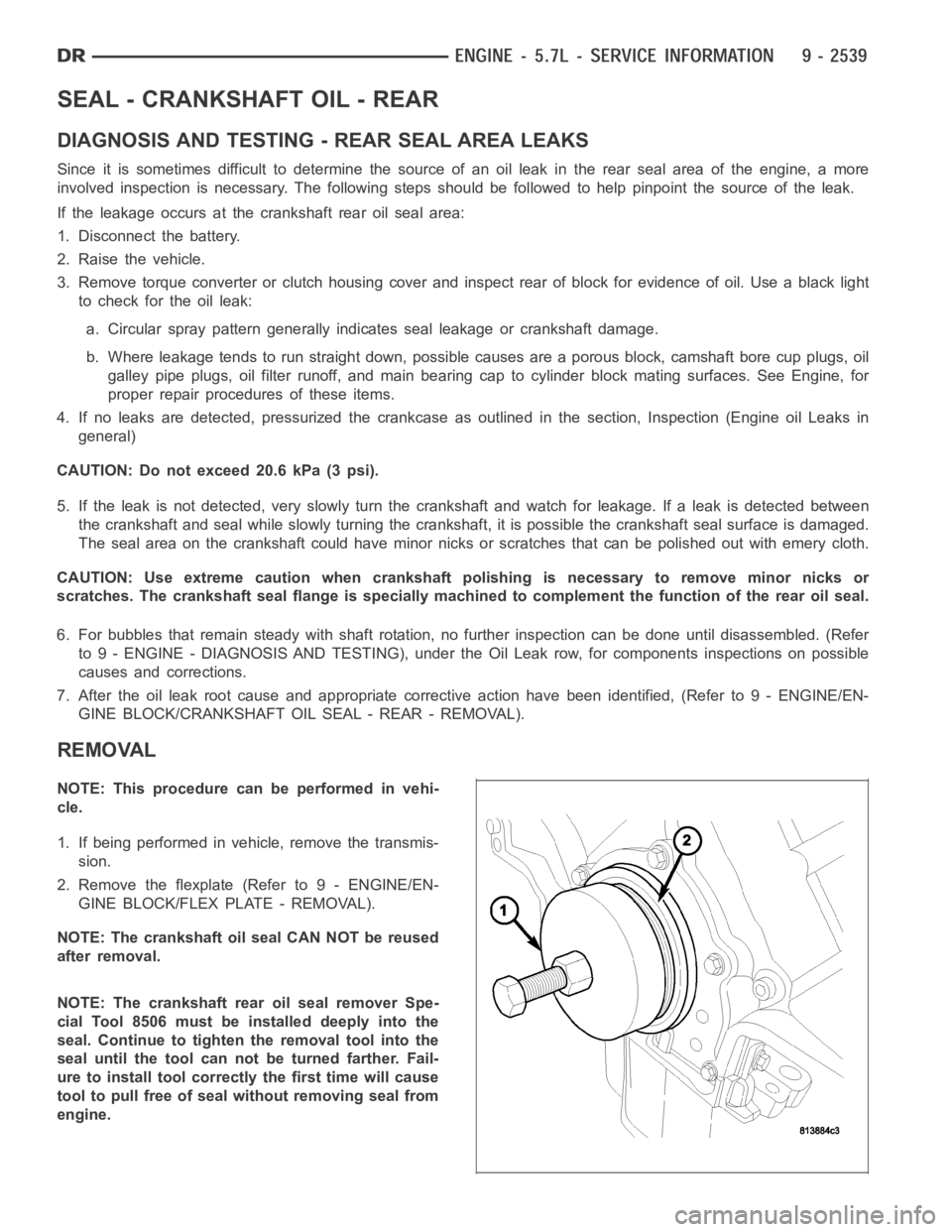
NOTE: The crankshaft rear oil seal remover Spe-
cial Tool 8506 must be installed deeply into the
seal. Continue to tighten the removal tool into the
seal until the tool can not be turned farther. Fail-
ure to install tool correctly the first time will cause
tool to pull free of seal without removing seal from
engine.
Page 1907 of 5267
CONDITION POSSIBLE CAUSES CORRECTION
11. Directed piston cooling nozzles
under piston, bad fit into main
carrier.11. Check directed piston cooling nozzles
position.
12. Loose oil rifle plug with saddle-jet
style nozzles12.Tighten oil rifle plug.
13. Loose directed piston cooling
nozzle.13. Tighten directed piston cooling nozzle.
14. Both J-jet and saddle jet style
cooling nozzle installed.14. Install correct style jet.
LUBRICATING OIL
PRESSURE TOO HIGH1. Pressure switch/gauge not
operating properly.1. Verify pressure switch is functioning
correctly. If not, replace switch/gauge.
ENGINE BREATHER
RESTRICTED2. Engine running too cold. 2. Refer to Coolant Temperature Below
Normal (Refer to 7 - COOLING -
DIAGNOSIS AND TESTING).
3. Oil viscosity too thick. 3. Make sure the correct oil is being used.
(Refer to LUBRICATION &
MAINTENANCE/FLUID TYPES -
DESCRIPTION).
4. Oil pressure relief valve stuck
closed or binding4. Check and replace valve.
LUBRICATING OIL LOSS 1. External leaks. 1. Visually inspect for oil leaks.Repair as
required.
2. Crankcase being overfilled. 2. Verify that the correct dipstick is being
used.
3. Incorrect oil specification or
viscosity.3. (a) Make sure the correct oil is being
used (Refer to LUBRICATION &
MAINTENANCE/FLUID TYPES -
DESCRIPTION).
(b) Look for reduced viscosity from dilution
with fuel.
(c) Review/reduce oil change intervals.
4. Oil cooler leak 4. Check and replace the oil cooler.
5. High blow-by forcing oil out the
breather.5. Check the breather tube area for signs of
oil loss. Perform the required repairs.
6. Turbocharger leaking oil to the air
intake.6. Inspect the air ducts for evidence of oil
transfer. Repair as required.
COMPRESSION KNOCKS 1. Air in the fuel system. 1. Identify location of air leak and repair. Do
not bleed high pressure fuel system.
2. Poor quality fuel or water/gasoline
contaminated fuel.2. Verify by operating from a temporary
tank with good fuel. Clean and flush the
fuel tank. Replace fuel/water separator filter.
3. Engine overloaded. 3. Verify the engine load rating is not being
exceeded.
4. Improperly operating injectors. 4. Check and replace misfiring/inoperative
injectors.
EXCESSIVE VIBRATION 1. Loose or broken engine mounts. 1. Replace engine mounts.
2. Damaged fan or improperly
operating accessories.2. Check and replace the vibrating
components.
Page 1908 of 5267
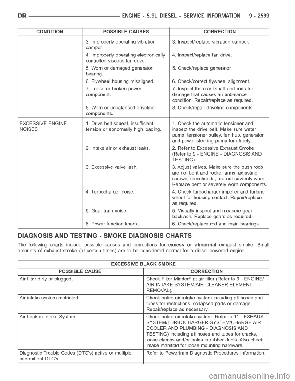
CONDITION POSSIBLE CAUSES CORRECTION
3. Improperly operating vibration
damper3. Inspect/replace vibration damper.
4. Improperly operating electronically
controlled viscous fan drive.4. Inspect/replace fan drive.
5. Worn or damaged generator
bearing.5. Check/replace generator.
6. Flywheel housing misaligned. 6. Check/correct flywheel alignment.
7. Loose or broken power
component.7. Inspect the crankshaft and rods for
damage that causes an unbalance
condition. Repair/replace as required.
8. Worn or unbalanced driveline
components.8. Check/repair driveline components.
EXCESSIVE ENGINE
NOISES1. Drive belt squeal, insufficient
tension or abnormally high loading.1. Check the automatic tensioner and
inspect the drive belt. Make sure water
pump, tensioner pulley, fan hub, generator
and power steering pump turn freely.
2. Intake air or exhaust leaks. 2. Refer to Excessive Exhaust Smoke
(Refer to 9 - ENGINE - DIAGNOSIS AND
TESTING).
3. Excessive valve lash. 3. Adjust valves. Make sure the push rods
are not bent and rocker arms, adjusting
screws, crossheads, are not severely worn.
Replace bent or severely worn components.
4. Turbocharger noise. 4. Check turbocharger impeller and turbine
wheel for housing contact. Repair/replace
as required.
5. Gear train noise. 5. Visually inspect and measure gear
backlash. Replace gears as required.
6. Power function knock. 6. Check/replace rod and main bearings.
DIAGNOSIS AND TESTING -SMOKE DIAGNOSIS CHARTS
The following charts include possible causes and corrections forexcess or abnormalexhaust smoke. Small
amounts of exhaust smoke (at certain times) are to be considered normal fora diesel powered engine.
EXCESSIVE BLACK SMOKE
POSSIBLE CAUSE CORRECTION
Air filter dirty or plugged. Check Filter Minder
at air filter (Refer to 9 - ENGINE/
AIR INTAKE SYSTEM/AIR CLEANER ELEMENT -
REMOVAL).
Air intake system restricted. Check entire air intake system including all hoses and
tubes for restrictions, collapsed parts or damage.
Repair/replace as necessary.
Air Leak in Intake System. Check entire air intake system (Refer to 11 - EXHAUST
SYSTEM/TURBOCHARGER SYSTEM/CHARGE AIR
COOLER AND PLUMBING - DIAGNOSIS AND
TESTING) including all hoses and tubes for cracks,
loose clamps and/or holes in rubber ducts. Also check
intake manifold for loose mounting hardware.
Diagnostic Trouble Codes (DTC’s) active or multiple,
intermittent DTC’s.Refer to Powertrain Diagnostic Procedures Information.
Page 1910 of 5267

EXCESSIVE WHITE SMOKE
POSSIBLE CAUSE CORRECTION
Fuel filter plugged. Refer to Powertrain Diagnostic Manual for fuel system
testing.
Fuel grade not correct or fuel quality is poor. Temporarily change fuel brands and note condition.
Change brand if necessary.
Fuel heater element or fuel heater temperature sensor
malfunctioning. This will cause wax type build-up in fuel
filter.Refer to Fuel Heater Testing (Refer to 14 - FUEL
SYSTEM/FUEL DELIVERY/FUEL HEATER -
DIAGNOSIS AND TESTING).
Fuel injector malfunctioning. A DTC should have been set. Perform “Cylinder
Performance Test
orCylinder cutout Testusing DRB
scan tool to isolate individual cylinders. Also refer to
Powertrain Diagnostic Procedures Information and,
(Refer to 14 - FUEL SYSTEM/FUEL INJECTION/FUEL
INJECTOR - DIAGNOSIS AND TESTING).
Fuel injector hold-downs loose. Torque to specifications.
Fuel injector protrusion not correct. Check washer (shim) at bottom of fuel injector for
correct thickness. (Referto 14 - FUEL SYSTEM/FUEL
INJECTION/FUEL INJECTOR - INSTALLATION)
Fuel injection pump malfunctioning. A DTC should have been set. Refer to Powertrain
Diagnostic Procedures Information.
Fuel supply side restriction. Refer to Powertrain Diagnostic Manual for fuel system
testing.
Fuel transfer (lift) pump malfunctioning. A DTC may have been set. Refer toPowertrain
Diagnostic Procedures Information.
Intake/Exhaust valve adjustments not correct (too tight). (Refer to 9 - ENGINE/CYLINDER HEAD/INTAKE/
EXHAUST VALVES & SEATS - STANDARD
PROCEDURE).
Intake manifold air temperature sensor malfunctioning. A DTC should havebeen set. Refer to Powertrain
Diagnostic Procedures Information.
Intake manifold heater circuit not functioning correctly in
cold weather.A DTC should have been set. Refer to Powertrain
Diagnostic Procedures Information. Also check heater
elements for correct operation.
Intake manifold heater elements not functioning
correctly in cold weather.A DTC should have been set if heater elements are
malfunctioning. Refer to Powertrain Diagnostic
Procedures Information.
Internal engine damage (scuffed cylinder). Analyze engine oil and inspect oil filter to locate area of
probable damage.
Restriction in fuel supply side of fuel system. Refer to Powertrain Diagnostic Manual for fuel system
testing.
EXCESSIVE BLUE SMOKE
POSSIBLE CAUSE CORRECTION
Dirty air cleaner or restricted turbocharger intake duct. Check Filter Minder
at air filter housing. (Refer to 9 -
ENGINE/AIR INTAKE SYSTEM/AIR CLEANER
ELEMENT - REMOVAL).
Air leak in boost system between turbocharger
compressor outlet and intake manifold.Service air charge system..
Obstruction in exhaust manifold. Remove exhaust manifold and inspect forblockage
(Refer to 9 - ENGINE/MANIFOLDS/EXHAUST
MANIFOLD - REMOVAL).
Page 1911 of 5267
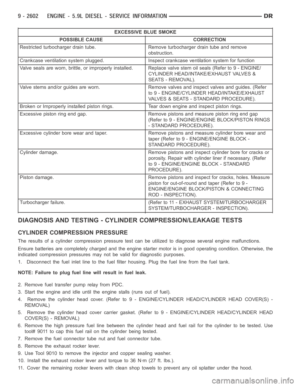
EXCESSIVE BLUE SMOKE
POSSIBLE CAUSE CORRECTION
Restricted turbocharger drain tube. Remove turbocharger drain tube and remove
obstruction.
Crankcase ventilation system plugged. Inspect crankcase ventilation system for function
Valve seals are worn, brittle, or improperly installed. Replace valve stemoilseals(Referto9-ENGINE/
CYLINDER HEAD/INTAKE/EXHAUST VALVES &
SEATS - REMOVAL).
Valve stems and/or guides are worn. Remove valves and inspect valves and guides. (Refer
to 9 - ENGINE/CYLINDER HEAD/INTAKE/EXHAUST
VALVES & SEATS - STANDARD PROCEDURE).
Broken or Improperly installed piston rings. Tear down engine and inspectpiston rings.
Excessive piston ring end gap. Remove pistons and measure piston ring end gap
(Refer to 9 - ENGINE/ENGINE BLOCK/PISTON RINGS
- STANDARD PROCEDURE).
Excessive cylinder bore wear and taper. Remove pistons and measure cylinder bore wear and
taper (Refer to 9 - ENGINE/ENGINE BLOCK -
STANDARD PROCEDURE).
Cylinder damage. Remove pistons and inspect cylinder bore for cracks or
porosity. Repair with cylinder liner if necessary. (Refer
to 9 - ENGINE/ENGINE BLOCK - STANDARD
PROCEDURE).
Piston damage. Remove pistons and inspect for cracks, holes. Measure
piston for out-of-round and taper (Refer to 9 -
ENGINE/ENGINE BLOCK/PISTON & CONNECTING
ROD - INSPECTION).
Turbocharger failure. (Refer to 11 - EXHAUST SYSTEM/TURBOCHARGER
SYSTEM/TURBOCHARGER - INSPECTION).
DIAGNOSIS AND TESTING - CYLINDER COMPRESSION/LEAKAGE TESTS
CYLINDER COMPRESSION PRESSURE
The results of a cylinder compressionpressure test can be utilized to diagnose several engine malfunctions.
Ensure batteries are completely charged and the engine starter motor is ingood operating condition. Otherwise, the
indicated compression pressures may not be valid for diagnostic purposes.
1. Disconnect the fuel inlet line to the fuel filter housing. Plug the fuel line from the fuel tank.
NOTE: Failure to plug fuel line will result in fuel leak.
2. Remove fuel transfer pump relay from PDC.
3. Start the engine and idle until the engine stalls (runs out of fuel).
4. Remove the cylinder head cover. (Refer to 9 - ENGINE/CYLINDER HEAD/CYLINDER HEAD COVER(S) -
REMOVAL)
5. Remove the cylinder head cover carrier gasket. (Refer to 9 - ENGINE/CYLINDER HEAD/CYLINDER HEAD
COVER(S) - REMOVAL)
6. Remove the high pressure fuel line between the cylinder head and fuel rail for the cylinder to be tested. Use
tool# 9011 to cap this fuel rail on the cylinder being tested.
7. Remove the fuel connector tube nut and fuel connector tube.
8. Remove the exhaust rocker lever.
9. Use Tool 9010 to remove the injector and copper sealing washer.
10. Install the exhaust rocker lever and torque to 36 Nꞏm (27 ft. lbs.).
11. Cover the remaining rocker levers with clean shop towels to prevent anyoil splatter under the hood.
Page 1914 of 5267
3. Place a shop towel around the fuel injectors to catch any fluid that may possibly be under pressure in the cyl-
inder head. Remove the fuel injectors (Refer to 14 - FUEL SYSTEM/FUEL INJECTION/FUEL INJECTOR -
REMOVAL).
4. With all injectors removed, rotatethe crankshaft using the crankshaftbarring tool (PN 7471–B).
5. Identify the fluid in the cylinders (coolant, fuel, oil, etc.).
6. Be sure all fluid has been removed from the cylinders.
7. Repair engine or components as necessary to prevent this problem from occurring again.
8. Squirt a small amount of engine oil into the cylinders to lubricate the walls. This will prevent damage on restart.
9. Install fuel injectors (Refer to 14 - FUEL SYSTEM/FUEL INJECTION/FUEL INJECTOR - INSTALLATION).
10. Drain engine oil. Remove and discard the oil filter (Refer to 9 - ENGINE/LUBRICATION/OIL FILTER -
REMOVAL).
11. Installthedrainplug.Tightentheplugto50Nꞏm(37ft.lbs.)torque.
12. Install a new oil filter (Refer to 9 - ENGINE/LUBRICATION/OIL FILTER - INSTALLATION).
13. Fill engine crankcase with the specified amount and grade of oil (Referto LUBRICATION & MAINTENANCE/
FLUID TYPES - SPECIFICATIONS).
14. Connect the negative cable(s) to the battery.
15. Start the engine and check for any leaks.
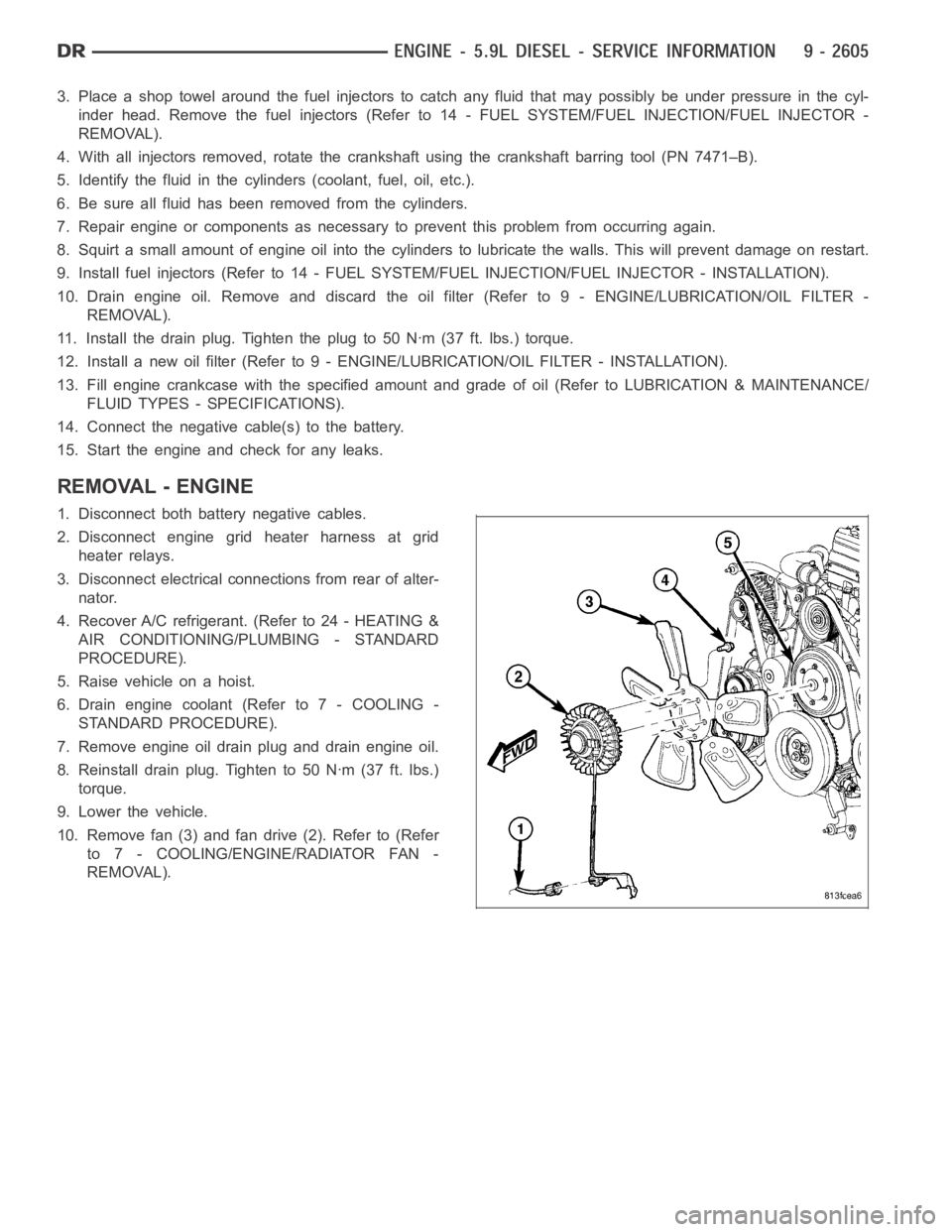
REMOVAL - ENGINE
1. Disconnect both battery negative cables.
2. Disconnect engine grid heater harness at grid
heater relays.
3. Disconnect electrical connections from rear of alter-
nator.
4. Recover A/C refrigerant. (Refer to 24 - HEATING &
AIR CONDITIONING/PLUMBING - STANDARD
PROCEDURE).
5. Raise vehicle on a hoist.
6. Drain engine coolant (Refer to 7 - COOLING -
STANDARD PROCEDURE).
7. Remove engine oil drain plug and drain engine oil.
8. Reinstall drain plug. Tighten to 50 Nꞏm (37 ft. lbs.)
torque.
9. Lower the vehicle.
10. Remove fan (3) and fan drive (2). Refer to (Refer
to 7 - COOLING/ENGINE/RADIATOR FAN -
REMOVAL).