2006 DODGE RAM SRT-10 air filter
[x] Cancel search: air filterPage 1587 of 5267
DIAGNOSIS AND TESTING
DIAGNOSIS AND TESTING - ENGINE OIL LEAK
Begin with a thorough visual inspection of the engine, particularly at thearea of the suspected leak. If an oil leak
source is not readily identifiable, thefollowingstepsshouldbefollowed:
1. Do not clean or degrease the engine at this time because some solvents maycause rubber to swell, temporarily
stopping the leak.
2. Add an oil soluble dye (use as recommended by manufacturer). Start the engine and let idle for approximately 15
minutes. Check the oil dipstick to make sure the dye is thoroughly mixed as indicated with a bright yellow color
under a black light.
3. Using a black light, inspect the entire engine for fluorescent dye, particularly at the suspected area of oil leak. If
the oil leak is found and identified, repair per service manual instructions.
4. If dye is not observed, drive the vehicle at various speeds for approximately 24 km (15 miles), and repeat inspec-
tion.If the oil leak source is not positively identified at this time, proceed with the air leak detection test method.
Air Leak Detection Test Method
1. Disconnect the breather cap to air cleaner hose at the breather cap end. Cap or plug breather cap nipple.
2. Remove the PCV valve from the cylinder head cover. Cap or plug the PCV valvegrommet.
3. Attach an air hose with pressure gauge and regulator to the dipstick tube.
CAUTION: Do not subject the engine assembly to more than 20.6 kPa (3 PSI) of test pressure.
4. Gradually apply air pressure from 1 psi to 2.5 psi maximum while applyingsoapy water at the suspected source.
Adjust the regulator to the suitable test pressure that provide the best bubbles which will pinpoint the leak
source. If the oil leak is detected and identified, repair per service manual procedures.
5. If the leakage occurs at the rear oil seal area, refer to the section, Inspection for Rear Seal Area Leak.
6. If no leaks are detected, turn off the air supply and remove the air hose and all plugs and caps. Install the PCV
valve and breather cap hose.
7. Clean the oil off the suspect oil leak area using a suitable solvent. Drive the vehicle at various speeds approx-
imately 24 km (15 miles). Inspect the engine for signs of an oil leak by usinga black light.
INSPECTION FOR REAR SEAL AREA LEAKS
Since it is sometimes difficult to determine the source of an oil leak in therear seal area of the engine, a more
involved inspection is necessary. The following steps should be followedto help pinpoint the source of the leak.
If the leakage occurs at the crankshaft rear oil seal area:
1. Disconnect the battery.
2. Raise the vehicle.
3. Remove torque converter or clutch housing cover and inspect rear of block for evidence of oil. Use a black light
to check for the oil leak:
a. Circular spray pattern generally indicates seal leakage or crankshaftdamage.
b. Where leakage tends to run straight down, possible causes are a porous block, oil galley pipe plugs, oil filter
runoff, and main bearing cap to cylinder block mating surfaces.
4. If no leaks are detected, pressurize the crankcase as outlined in the, Inspection (Engine oil Leaks in general)
CAUTION: Do not exceed 20.6 kPa (3 psi).
5. If the leak is not detected, very slowly turn the crankshaft and watch forleakage. If a leak is detected between
the crankshaft and seal while slowly turning the crankshaft, it is possible the crankshaft seal surface is damaged.
The seal area on the crankshaft could have minor nicks or scratches that canbe polished out with emery cloth.
CAUTION: Use extreme caution when crankshaft polishing is necessary to remove minor nicks and
scratches. The crankshaft seal flange is especially machined to complement the function of the rear oil seal.
6. For bubbles that remain steady with shaft rotation, no further inspection can be done until disassembled.
Page 1588 of 5267
DIAGNOSIS AND TESTING - CHECKING ENGINE OIL PRESSURE
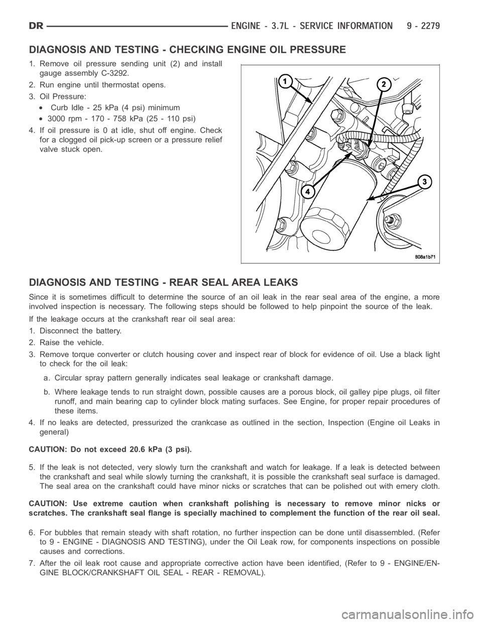
1. Remove oil pressure sending unit (2) and install
gauge assembly C-3292.
2. Run engine until thermostat opens.
3. Oil Pressure:
Curb Idle - 25 kPa (4 psi) minimum
3000 rpm - 170 - 758 kPa (25 - 110 psi)
4. If oil pressure is 0 at idle, shut off engine. Check
for a clogged oil pick-up screen or a pressure relief
valve stuck open.
DIAGNOSIS AND TESTING - REAR SEAL AREA LEAKS
Since it is sometimes difficult to determine the source of an oil leak in therear seal area of the engine, a more
involved inspection is necessary. The following steps should be followedto help pinpoint the source of the leak.
If the leakage occurs at the crankshaft rear oil seal area:
1. Disconnect the battery.
2. Raise the vehicle.
3. Remove torque converter or clutch housing cover and inspect rear of block for evidence of oil. Use a black light
to check for the oil leak:
a. Circular spray pattern generally indicates seal leakage or crankshaftdamage.
b. Where leakage tends to run straight down, possible causes are a porous block, oil galley pipe plugs, oil filter
runoff, and main bearing cap to cylinder block mating surfaces. See Engine, for proper repair procedures of
these items.
4. If no leaks are detected, pressurized the crankcase as outlined in the section, Inspection (Engine oil Leaks in
general)
CAUTION: Do not exceed 20.6 kPa (3 psi).
5. If the leak is not detected, very slowly turn the crankshaft and watch forleakage. If a leak is detected between
the crankshaft and seal while slowly turning the crankshaft, it is possible the crankshaft seal surface is damaged.
The seal area on the crankshaft could have minor nicks or scratches that canbe polished out with emery cloth.
CAUTION: Use extreme caution when crankshaft polishing is necessary to remove minor nicks or
scratches. The crankshaft seal flange is specially machined to complement the function of the rear oil seal.
6. For bubbles that remain steady with shaft rotation, no further inspection can be done until disassembled. (Refer
to 9 - ENGINE - DIAGNOSIS AND TESTING), under the Oil Leak row, for components inspections on possible
causes and corrections.
7. After the oil leak root cause and appropriate corrective action have been identified, (Refer to 9 - ENGINE/EN-
GINE BLOCK/CRANKSHAFT OIL SEAL - REAR - REMOVAL).
Page 1625 of 5267
ENGINE - 4.7L - SERVICE INFORMATION
DIAGNOSIS AND TESTING
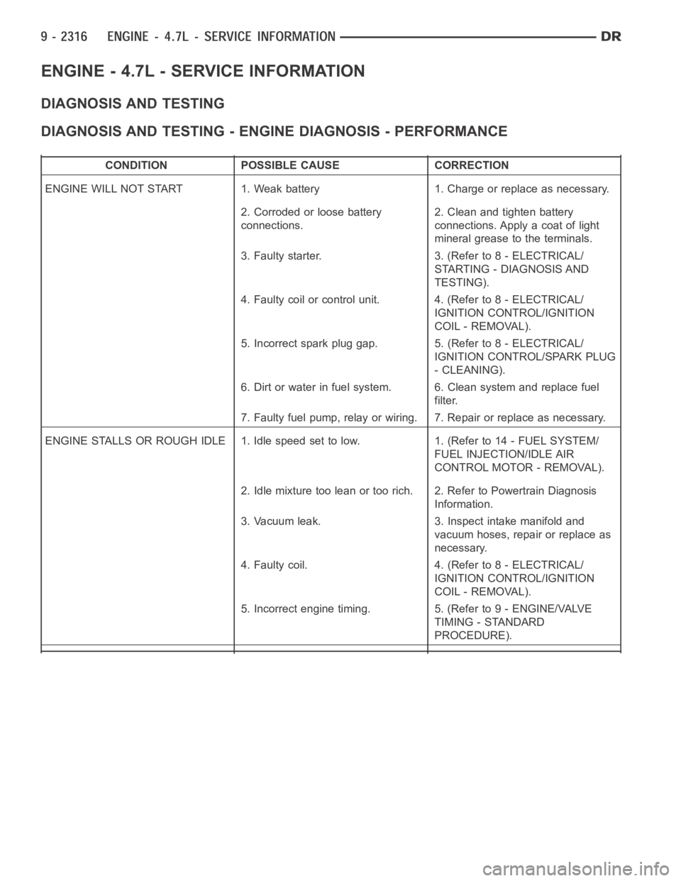
DIAGNOSIS AND TESTING - ENGINE DIAGNOSIS - PERFORMANCE
CONDITION POSSIBLE CAUSE CORRECTION
ENGINE WILL NOT START 1. Weak battery 1. Charge or replace as necessary.
2. Corroded or loose battery
connections.2. Clean and tighten battery
connections. Apply a coat of light
mineral grease to the terminals.
3. Faulty starter. 3. (Refer to 8 - ELECTRICAL/
STARTING - DIAGNOSIS AND
TESTING).
4. Faulty coil or control unit. 4. (Refer to 8 - ELECTRICAL/
IGNITION CONTROL/IGNITION
COIL - REMOVAL).
5. Incorrect spark plug gap. 5. (Refer to 8 - ELECTRICAL/
IGNITION CONTROL/SPARK PLUG
- CLEANING).
6. Dirt or water in fuel system. 6. Clean system and replace fuel
filter.
7. Faulty fuel pump, relay or wiring. 7. Repair or replace as necessary.
ENGINE STALLS OR ROUGH IDLE 1. Idle speed set to low. 1. (Refer to 14 - FUEL SYSTEM/
FUEL INJECTION/IDLE AIR
CONTROL MOTOR - REMOVAL).
2. Idle mixture too lean or too rich. 2. Refer to Powertrain Diagnosis
Information.
3. Vacuum leak. 3. Inspect intake manifold and
vacuum hoses, repair or replace as
necessary.
4. Faulty coil. 4. (Refer to 8 - ELECTRICAL/
IGNITION CONTROL/IGNITION
COIL - REMOVAL).
5. Incorrect engine timing. 5. (Refer to 9 - ENGINE/VALVE
TIMING - STANDARD
PROCEDURE).
Page 1651 of 5267
ELEMENT - AIR CLEANER
REMOVAL
Filter Element Only
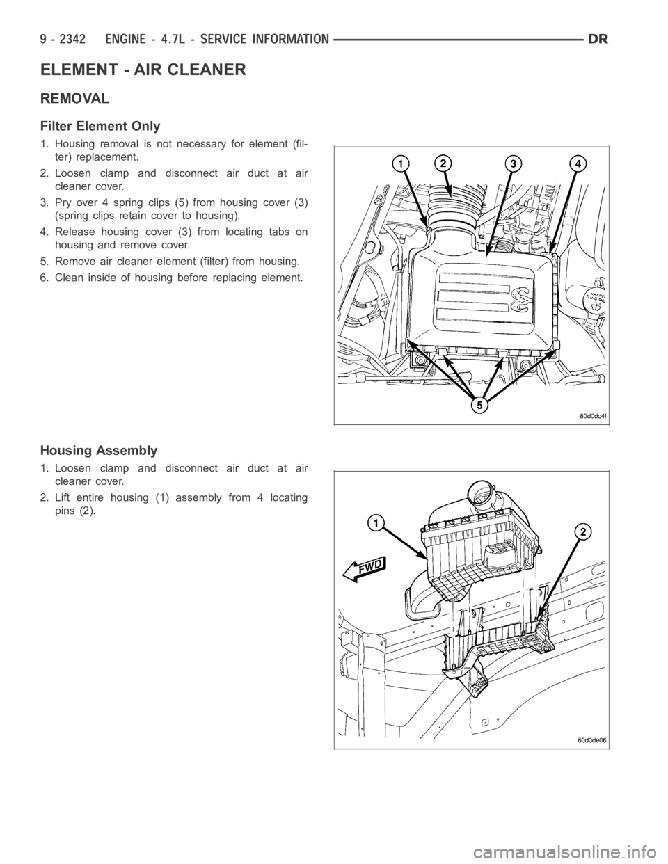
1. Housing removal is not necessary for element (fil-
ter) replacement.
2. Loosen clamp and disconnect air duct at air
cleaner cover.
3. Pry over 4 spring clips (5) from housing cover (3)
(spring clips retain cover to housing).
4. Release housing cover (3) from locating tabs on
housing and remove cover.
5. Remove air cleaner element (filter) from housing.
6. Clean inside of housing before replacing element.
Housing Assembly
1. Loosen clamp and disconnect air duct at air
cleaner cover.
2. Lift entire housing (1) assembly from 4 locating
pins (2).
Page 1652 of 5267
INSTALLATION
1. Install filter element into housing.
2. Position housing cover into housing locating tabs.
3. Pry up 4 spring clips and lock cover to housing.
4. Install air duct to air cleaner cover and tighten hose clamp to 3 Nꞏm (30 in.lbs.)torque.
5. If any other hose clamps were removed from air intake system, tighten themto3.4Nꞏm(30in.lbs.)torque.
6. If any bolts were removed from air resonator housing or air intake tubing, tighten them to 4.5 Nꞏm (40 in. lbs.)
torque.
Page 1678 of 5267
COVER - CYLINDER HEAD
DESCRIPTION
The cylinder head covers are made of injection molded thermo-set plastic,and are not interchangeable from side-
to-side. It is imperativethat nothing rest on the cylinder head covers. Prolonged contact with other items may wear
a hole in the cylinder head cover.
REMOVAL
REMOVAL - RIGHT SIDE
1. Disconnect battery negative cable.
2. Remove air cleaner assembly, resonator assembly and air inlet hose.
3. Drain cooling system (Refer to 7 - COOLING - STANDARD PROCEDURE).
4. Remove accessory drive belt (Refer to 7 - COOLING/ACCESSORY DRIVE/DRIVE BELTS - REMOVAL).
5. Remove air conditioning compressor retaining bolts and move compressortotheleft.
6. Remove heater hoses.
7. Disconnect injector and ignition coil connectors.
8. Disconnect and remove positive crankcase ventilation (PCV) hose.
9. Remove oil fill tube.
10. Un-clip injector and ignition coil harness and move away from cylinderhead cover.
11. Remove right rear breather tube and filter assembly.
12. Remove cylinder head cover retaining bolts.
13. Remove cylinder head cover.
NOTE: The gasket may be used again, provided no cuts, tears, or deformationhas occurred.
REMOVAL - LEFT SIDE
1. Disconnect negative cable from battery.
2. Remove the resonator assemble and air inlet hose.
3. Disconnect injector connectors and un-clip the injector harness.
4. Route injector harness in front of cylinder head cover.
5. Disconnect the left side breather tube and remove the breather tube.
6. Remove the cylinder head cover mounting bolts.
7. Remove cylinder head cover and gasket.
NOTE: The gasket may be used again, provided no cuts, tears, or deformationhas occurred.
CLEANING
Clean cylinder head cover gasket surface.
Clean head rail, if necessary.
Page 1679 of 5267
INSTALLATION
INSTALLATION - RIGHT SIDE
CAUTION: Do not use harsh cleaners to clean the
cylinder head covers. Severe damage to covers
may occur.
1. Clean cylinder head cover and both sealing sur-
faces. Inspect and replace gasket as necessary.
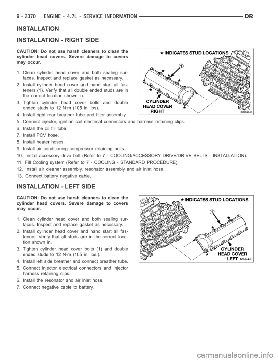
2. Install cylinder head cover and hand start all fas-
teners (1). Verify that all double ended studs are in
the correct location shown in.
3. Tighten cylinder head cover bolts and double
ended studs to 12 Nꞏm (105 in. lbs).
4. Install right rear breather tube and filter assembly.
5. Connect injector, ignition coil electrical connectors and harness retaining clips.
6. Install the oil fill tube.
7. Install PCV hose.
8. Install heater hoses.
9. Install air conditioning compressor retaining bolts.
10. Install accessory drive belt (Refer to 7 - COOLING/ACCESSORY DRIVE/DRIVE BELTS - INSTALLATION).
11. Fill Cooling system (Refer to 7 - COOLING - STANDARD PROCEDURE).
12. Install air cleaner assembly, resonator assembly and air inlet hose.
13. Connect battery negative cable.
INSTALLATION - LEFT SIDE
CAUTION: Do not use harsh cleaners to clean the
cylinder head covers. Severe damage to covers
may occur.
1. Clean cylinder head cover and both sealing sur-
faces. Inspect and replace gasket as necessary.
2. Install cylinder head cover and hand start all fas-
teners. Verify that all studs are in the correct loca-
tion shown in.
3. Tighten cylinder head cover bolts (1) and double
ended studs to 12 Nꞏm (105 in. lbs.).
4. Install left side breather and connect breather tube.
5. Connect injector electrical connectors and injector
harness retaining clips.
6. Install the resonator and air inlet hose.
7. Connect negative cable to battery.
Page 1688 of 5267
ENGINE BLOCK
DESCRIPTION
The cylinder block is made of cast iron.The block is a closed deck design with the left bank forward. To provide
high rigidity and improved NVH an enhanced compacted graphite bedplate isbolted to the block. The block design
allows coolant flow between the cylinders bores, and an internal coolant bypass to a single poppet inlet thermostat
is included in the cast aluminum front cover.
STANDARD PROCEDURE - CYLINDER BORE HONING
Before honing, stuff plenty of clean shop towels under
the bores and over the crankshaft to keep abrasive
materials from entering the crankshaft area.
1. Used carefully, the Cylinder Bore Sizing Hone
C-823, equipped with 220 grit stones, is the best
tool for this job. In addition to deglazing, it will
reduce taper and out-of-round, as well as removing
light scuffing, scoring and scratches. Usually, a few
strokes will clean up a bore and maintain the
required limits.
CAUTION: DO NOT use rigid type hones to remove
cylinder wall glaze.
2. Deglazing of the cylinder walls may be done if the
cylinder bore is straight and round. Use a cylinder
surfacing hone, Honing Tool C-3501, equipped with
280 grit stones (C-3501-3810). about 20-60
strokes, depending on the bore condition, will be
sufficient to provide a satisfactory surface. Using
honing oil C-3501-3880, or a light honing oil, avail-
able from major oil distributors.
CAUTION: DO NOT use engine or transmission oil, mineral spirits, or kerosene.
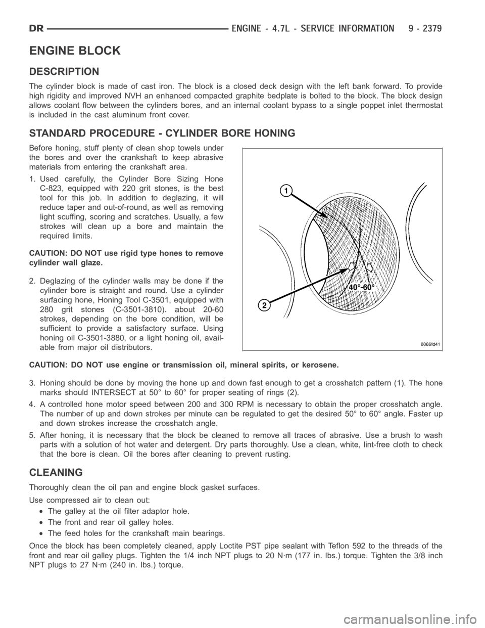
3. Honing should be done by moving the hone up and down fast enough to get a crosshatch pattern (1). The hone
marks should INTERSECT at 50° to 60° for proper seating of rings (2).
4. A controlled hone motor speed between 200 and 300 RPM is necessary to obtain the proper crosshatch angle.
The number of up and down strokes per minute can be regulated to get the desired 50° to 60° angle. Faster up
and down strokes increase the crosshatch angle.
5. After honing, it is necessary that the block be cleaned to remove all traces of abrasive. Use a brush to wash
parts with a solution of hot water and detergent. Dry parts thoroughly. Usea clean, white, lint-free cloth to check
that the bore is clean. Oil the bores after cleaning to prevent rusting.
CLEANING
Thoroughly clean the oil pan and engine block gasket surfaces.
Use compressed air to clean out:
The galley at the oil filter adaptor hole.
The front and rear oil galley holes.
The feed holes for the crankshaft main bearings.
Once the block has been completely cleaned, apply Loctite PST pipe sealantwith Teflon 592 to the threads of the
front and rear oil galley plugs. Tighten the 1/4 inch NPT plugs to 20 Nꞏm (177in. lbs.) torque. Tighten the 3/8 inch
NPT plugs to 27 Nꞏm (240 in. lbs.) torque.