Page 4875 of 5267
B10BE–CONDENSER FAN CONTROL CIRCUIT LOW (TIPM)
For a complete wiring diagramRefer to Section 8W.
Page 4876 of 5267
When Monitored:
With the ignition on. Battery voltage greater than 10.4 volts.
Set Condition:
If the Totally Integrated Power Module (TIPM) detects a shorted low condition in the (C123) Condenser Fan
Control circuit.
Possible Causes
(C123) CONDENSER FAN CONTROL OUTPUT CIRCUIT SHORTED TO GROUND
CONDENSER FAN MOTOR
TIPM
Diagnostic Test
1.VERIFY DTC IS ACTIVE
Turn the ignition on.
With the scan tool, erase TIPM DTCs.
Turn the ignition off, wait 10 seconds, and turn the ignition on.
With the scan tool, actuate the Condenser Fan.
With the scan tool, read TIPM DTCs.
Does this DTC reset?
Ye s>>
With the scan tool, de-actuate the Condenser Fan. Then, Go To 2
No>>
With the scan tool, de-actuate the Condenser Fan. Then, check for an intermittent condition by inspect-
ing the related wiring harness for chafed, pierced, pinched, and partially broken wires. Also, inspect the
related connectors for broken, bent, corroded, and contaminated terminals.
Perform BODY VERIFICATION TEST – VER 1. (Refer to 8 - ELECTRICAL/ELECTRONIC CONTROL
MODULES - STANDARD PROCEDURE).
2.CHECK (C123) CONDENSER FAN CONTROL OUTPUT CIRCUIT FOR A SHORT TO GROUND
Turn the ignition off.
Disconnect the TIPM C8 harness connector.
Disconnect the Condenser Fan Motor harness connector.
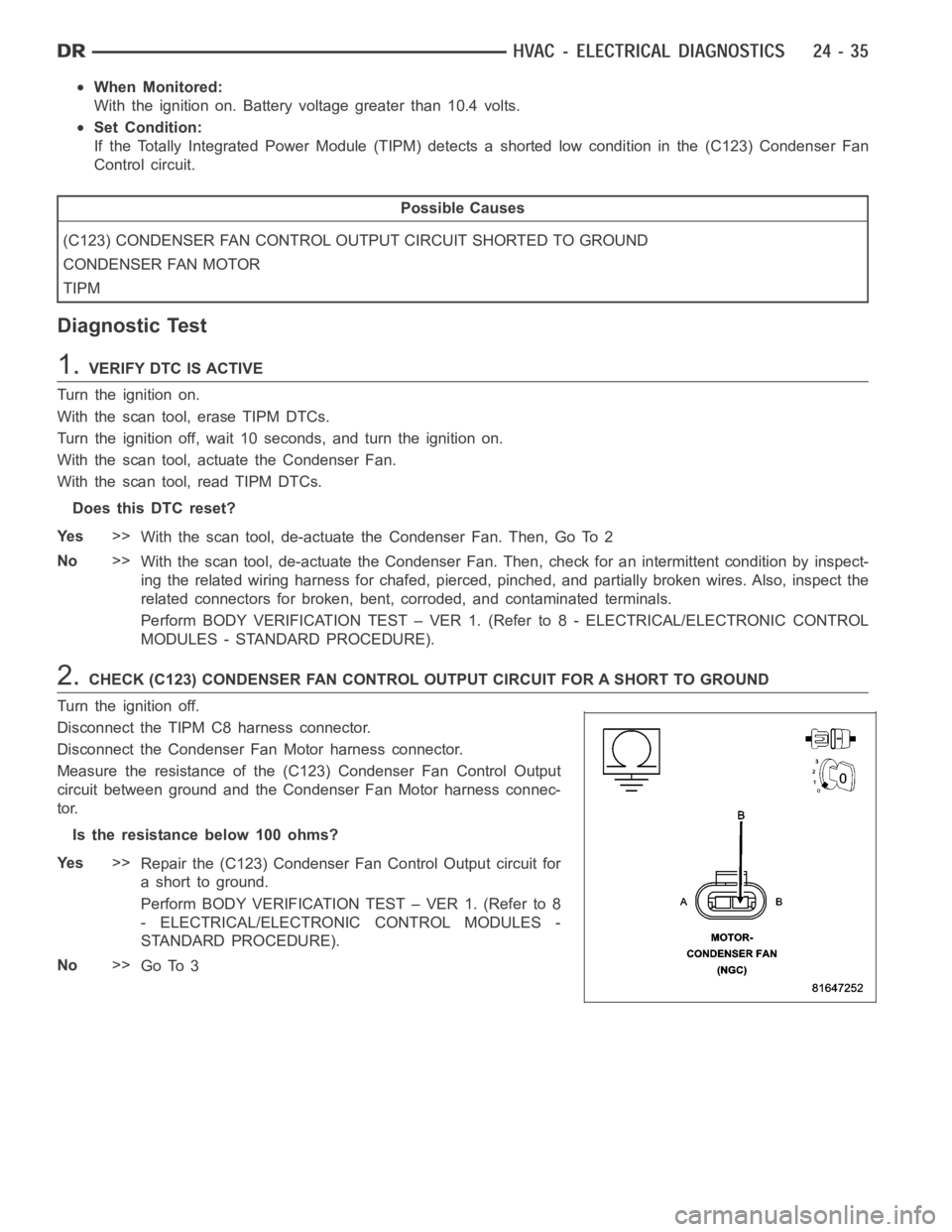
Measure the resistance of the (C123) Condenser Fan Control Output
circuit between ground and the Condenser Fan Motor harness connec-
tor.
Istheresistancebelow100ohms?
Ye s>>
Repair the (C123) Condenser Fan Control Output circuit for
a short to ground.
Perform BODY VERIFICATION TEST – VER 1. (Refer to 8
- ELECTRICAL/ELECTRONIC CONTROL MODULES -
STANDARD PROCEDURE).
No>>
Go To 3
Page 4877 of 5267
3.CHECK FOR A SHORTED CONDENSER FAN MOTOR
Reconnect the TIPM C8 harness connector.
Ignition on, engine not running.
With the scan tool, actuate the Condenser Fan.
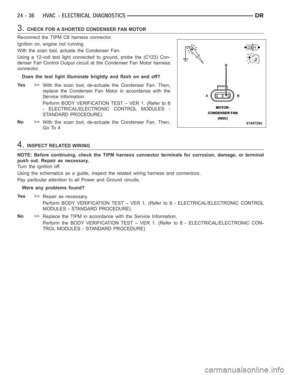
Using a 12-volt test light connected to ground, probe the (C123) Con-
denser Fan Control Output circuit at the Condenser Fan Motor harness
connector.
Does the test light illuminate brightly and flash on and off?
Ye s>>
With the scan tool, de-actuate the Condenser Fan. Then,
replace the Condenser Fan Motor in accordance with the
Service Information.
Perform BODY VERIFICATION TEST – VER 1. (Refer to 8
- ELECTRICAL/ELECTRONIC CONTROL MODULES -
STANDARD PROCEDURE).
No>>
With the scan tool, de-actuate the Condenser Fan. Then,
Go To 4
4.INSPECT RELATED WIRING
NOTE: Before continuing, check the TIPM harness connector terminals for corrosion, damage, or terminal
push out. Repair as necessary.
Turn the ignition off.
Using the schematics as a guide, inspect the related wiring harness and connectors.
Pay particular attention to all Power and Ground circuits.
Were any problems found?
Ye s>>
Repair as necessary.
Perform BODY VERIFICATION TEST – VER 1. (Refer to 8 - ELECTRICAL/ELECTRONIC CONTROL
MODULES - STANDARD PROCEDURE).
No>>
Replace the TIPM in accordance with the Service Information.
Perform the BODY VERIFICATION TEST – VER 1. (Refer to 8 - ELECTRICAL/ELECTRONIC CON-
TROL MODULES - STANDARD PROCEDURE)
Page 4878 of 5267
B10BF–CONDENSER FAN CONTROL CIRCUIT HIGH (TIPM)
For a complete wiring diagramRefer to Section 8W.
Page 4879 of 5267
When Monitored:
With the ignition on. Battery voltage greater than 10.4 volts.
Set Condition:
If the Totally Integrated Power Module (TIPM) detects a shorted high condition in the (C123) Condenser Fan
Control circuit.
Possible Causes
(C123) CONDENSER FAN CONTROL OUTPUT CIRCUIT SHORTED TO BATTERY VOLTAGE
EXCESSIVE RESISTANCE IN THE (Z823) GROUND CIRCUIT
CONDENSER FAN MOTOR
TIPM
Diagnostic Test
1.VERIFY DTC IS ACTIVE
Turn the ignition on.
With the scan tool, erase TIPM DTCs.
Turn the ignition off, wait 10 seconds, and turn the ignition on.
With the scan tool, actuate the Condenser Fan.
With the scan tool, read TIPM DTCs.
Does this DTC reset?
Ye s>>
With the scan tool, de-actuate the Condenser Fan. Then, Go To 2
No>>
With the scan tool, de-actuate the Condenser Fan. Then, check for an intermittent condition by inspect-
ing the related wiring harness for chafed, pierced, pinched, and partially broken wires. Also, inspect the
related connectors for broken, bent, corroded, and contaminated terminals.
Perform BODY VERIFICATION TEST – VER 1. (Refer to 8 - ELECTRICAL/ELECTRONIC CONTROL
MODULES - STANDARD PROCEDURE).
2.CHECK (C123) CONDENSER FAN CONTROL OUTPUT CIRCUIT FOR A SHORT TO BATTERY VOLTA G E
Turn the ignition off
Disconnect the TIPM C8 harness connector.
Disconnect the Condenser Fan Motor harness connector.
Ignition on, engine not running.
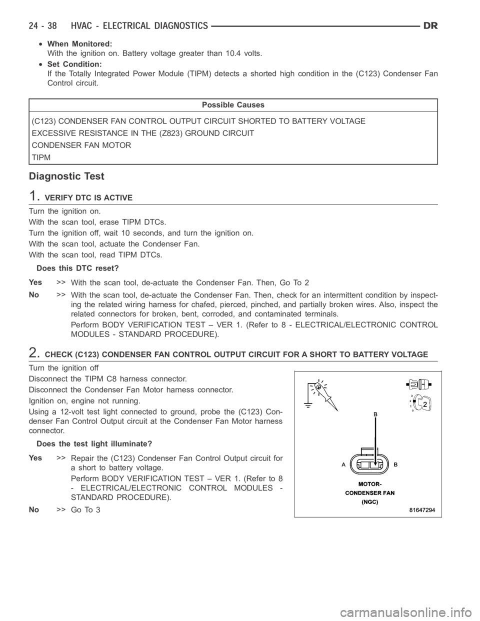
Using a 12-volt test light connected to ground, probe the (C123) Con-
denser Fan Control Output circuit at the Condenser Fan Motor harness
connector.
Does the test light illuminate?
Ye s>>
Repair the (C123) Condenser Fan Control Output circuit for
a short to battery voltage.
Perform BODY VERIFICATION TEST – VER 1. (Refer to 8
- ELECTRICAL/ELECTRONIC CONTROL MODULES -
STANDARD PROCEDURE).
No>>
Go To 3
Page 4880 of 5267
3.CHECK (Z823) GROUND CIRCUIT FOR AN OPEN
Turn the ignition off.
Reconnect the TIPM C8 harness connector.
NOTE: The test light should illuminate brightly. Compare the
brightness to that of a direct connection to the battery.
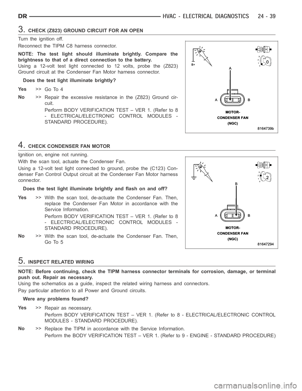
Using a 12-volt test light connected to 12 volts, probe the (Z823)
Ground circuit at the Condenser Fan Motor harness connector.
Does the test light illuminate brightly?
Ye s>>
Go To 4
No>>
Repair the excessive resistance in the (Z823) Ground cir-
cuit.
Perform BODY VERIFICATION TEST – VER 1. (Refer to 8
- ELECTRICAL/ELECTRONIC CONTROL MODULES -
STANDARD PROCEDURE).
4.CHECK CONDENSER FAN MOTOR
Ignition on, engine not running.
With the scan tool, actuate the Condenser Fan.
Using a 12-volt test light connected to ground, probe the (C123) Con-
denser Fan Control Output circuit at the Condenser Fan Motor harness
connector.
Does the test light illuminate brightly and flash on and off?
Ye s>>
With the scan tool, de-actuate the Condenser Fan. Then,
replace the Condenser Fan Motor in accordance with the
Service Information.
Perform BODY VERIFICATION TEST – VER 1. (Refer to 8
- ELECTRICAL/ELECTRONIC CONTROL MODULES -
STANDARD PROCEDURE).
No>>
With the scan tool, de-actuate the Condenser Fan. Then,
Go To 5
5.INSPECT RELATED WIRING
NOTE: Before continuing, check the TIPM harness connector terminals for corrosion, damage, or terminal
push out. Repair as necessary.
Using the schematics as a guide, inspect the related wiring harness and connectors.
Pay particular attention to all Power and Ground circuits.
Were any problems found?
Ye s>>
Repair as necessary.
Perform BODY VERIFICATION TEST – VER 1. (Refer to 8 - ELECTRICAL/ELECTRONIC CONTROL
MODULES - STANDARD PROCEDURE).
No>>
Replace the TIPM in accordance with the Service Information.
Perform the BODY VERIFICATION TEST – VER 1. (Refer to 9 - ENGINE - STANDARD PROCEDURE)
Page 4881 of 5267
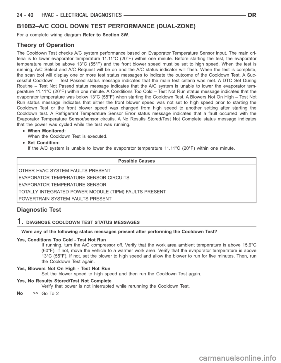
B10B2–A/C COOL DOWN TEST PERFORMANCE (DUAL-ZONE)
For a complete wiring diagramRefer to Section 8W.
Theory of Operation
The Cooldown Test checks A/C system performance based on Evaporator Temperature Sensor input. The main cri-
teria is to lower evaporator temperature 11.11°C (20°F) within one minute. Before starting the test, the evaporator
temperature must be above 13°C (55°F) and the front blower speed must be setto high speed. When the test is
running, A/C Select and A/C Request will be on and the A/C status indicator will flash. When the test is complete,
the scan tool will display one or more test status messages to indicate the outcome of the Cooldown Test. A Suc-
cessful Cooldown – Test Passed status message indicates that the main testcriteria was met. A DTC Set During
Routine – Test Not Passed status message indicates that the A/C system is unable to lower the evaporator tem-
perature 11.11°C (20°F) within one minute. A Conditions Too Cold – Test NotRun status message indicates that the
evaporator temperature was below 13°C (55°F) when starting the Cooldown Test. A Blowers Not On High – Test Not
Run status message indicates that either the front blower speed was not setto high speed prior to starting the
Cooldown Test or the front blower speed was changed from high speed to another setting after starting the
Cooldown test. A Refrigerant Temperature Sensor Error status message indicates that a fault occurred with the
Evaporator Temperature Sensor/sensor circuits. A No Results Stored/Test Not Complete status message indicates
that the power was cycled while the test was running.
When Monitored:
When the Cooldown Test is executed.
Set Condition:
If the A/C system is unable to lower the evaporator temperature 11.11°C (20°F) within one minute.
Possible Causes
OTHER HVAC SYSTEM FAULTS PRESENT
EVAPORATOR TEMPERATURE SENSOR CIRCUITS
EVAPORATOR TEMPERATURE SENSOR
TOTALLY INTEGRATED POWER MODULE (TIPM) FAULTS PRESENT
POWERTRAIN SYSTEM FAULTS PRESENT
Diagnostic Test
1.DIAGNOSE COOLDOWN TEST STATUS MESSAGES
WereanyofthefollowingstatusmessagespresentafterperformingtheCooldown Test?
Yes, Conditions Too Cold - Test Not Run
If running, turn the A/C compressor off. Verify that the work area ambient temperature is above 15.6°C
(60°F). If not, move the vehicle to a warmer work area. Verify that the evaporator temperature is above
13°C (55°F). If not, set the blower to high speed and allow the blower to run for five minutes. Then, run
the Cooldown Test again.
Yes, Blowers Not On High - Test Not Run
Set the blower speed to high speed and then run the Cooldown Test again.
Yes, No Results Stored/Test Not Complete
Verify that power is not interrupted while rerunning the Cooldown Test.
No>>
Go To 2
Page 4883 of 5267
B10C0–CONDENSER FAN CONTROL CIRCUIT OPEN (TIPM)
For a complete wiring diagramRefer to Section 8W.