2006 DODGE RAM SRT-10 wiring
[x] Cancel search: wiringPage 4312 of 5267
MOTOR-SHIFT
DESCRIPTION
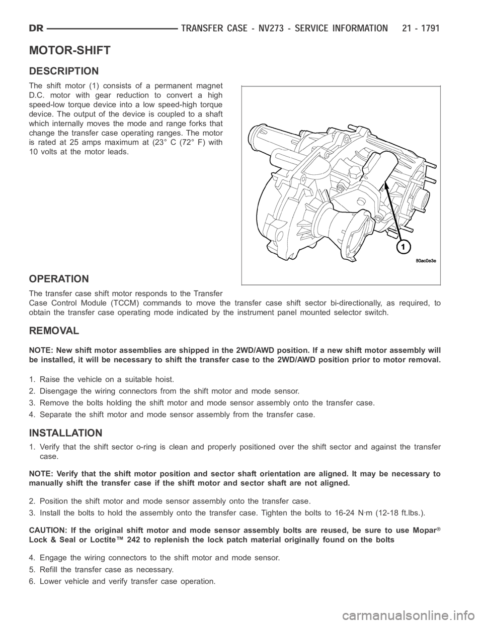
The shift motor (1) consists of a permanent magnet
D.C. motor with gear reduction to convert a high
speed-low torque device into a low speed-high torque
device. The output of the device is coupled to a shaft
which internally moves the mode and range forks that
change the transfer case operating ranges. The motor
is rated at 25 amps maximum at (23° C (72° F) with
10 volts at the motor leads.
OPERATION
The transfer case shift motor responds to the Transfer
Case Control Module (TCCM) commands to move the transfer case shift sectorbi-directionally, as required, to
obtain the transfer case operating mode indicated by the instrument panelmounted selector switch.
REMOVAL
NOTE: New shift motor assemblies are shipped in the 2WD/AWD position. If a new shift motor assembly will
be installed, it will be necessary to shift the transfer case to the 2WD/AWDposition prior to motor removal.
1. Raise the vehicle on a suitable hoist.
2. Disengage the wiring connectors from the shift motor and mode sensor.
3. Remove the bolts holding the shift motor and mode sensor assembly onto the transfer case.
4. Separate the shift motor and mode sensor assembly from the transfer case.
INSTALLATION
1. Verify that the shift sector o-ring is clean and properly positioned over the shift sector and against the transfer
case.
NOTE: Verify that the shift motor position and sector shaft orientation are aligned. It may be necessary to
manually shift the transfer case if the shift motor and sector shaft are notaligned.
2. Position the shift motor and mode sensor assembly onto the transfer case.
3. Install the bolts to hold the assembly onto the transfer case. Tighten the bolts to 16-24 Nꞏm (12-18 ft.lbs.).
CAUTION: If the original shift motor and mode sensor assembly bolts are reused, be sure to use Mopar
Lock & Seal or Loctite™ 242 to replenish the lock patch material originallyfound on the bolts
4. Engage the wiring connectors to the shift motor and mode sensor.
5. Refill the transfer case as necessary.
6. Lower vehicle and verify transfer case operation.
Page 4339 of 5267
BODY
WARNING
SAFETY PRECAUTIONS AND WARNINGS
WARNING: Use an OSHA approved breathing filter when spraying paint or solvents in a confined area. Per-
sonal injury can result.
Avoidprolongedskincontactwithpetroleumoralcohol–basedcleaningsolvents. Personal injury can
result.
Do not stand under a hoisted vehicle that is not properly supported on safety stands. Personal injury can
result.
CAUTION: When holes must be drilled or punched in an inner body panel, verify depth of space to the outer
body panel, electrical wiring, or other components. Damage to vehicle canresult.
Do not weld exterior panels unless combustible material on the interior ofvehicle is removed from the
repair area. Fire or hazardous conditions, can result.
Always have a fire extinguisher ready for use when welding.
Disconnect the negative (-) cable clamp from the battery when servicing electrical components that are
live when the ignition is OFF. Damage to electrical system can result.
Do not use abrasive chemicals or compounds on painted surfaces. Damage to finish can result.
Do not use harsh alkaline based cleaning solvents on painted or upholstered surfaces. Damage to finish
or color can result.
Do not hammer or pound on plastic trim panel when servicing interior trim. Plastic panels can break.
DIAGNOSIS AND TESTING
WAT E R L E A K S
Water leaks can be caused by poor sealing, improper body component alignment, body seam porosity, missing
plugs, or blocked drain holes. Centrifugal and gravitational force can cause water to drip from a location away from
the actual leak point, making leak detection difficult. All body sealing points should be water tight in normal wet-
driving conditions. Water flowing downward from the front of the vehicle should not enter the passenger or luggage
compartment. Moving sealing surfaces will not always seal water tight under all conditions. At times, side glass or
door seals will allow water to enter the passenger compartment during highpressure washing or hard driving rain
(severe) conditions. Overcompensating on door or glass adjustments to stop a water leak that occurs under severe
conditions can cause premature sealwear and excessive closing or latching effort. After completing a repair, water
test vehicle to verify leak has stopped before returning vehicle to use.
VISUAL INSPECTION BEFORE WATER LEAK TESTS
Verify that floor and body plugs are in place, body drains are clear, and body components are properly aligned and
sealed. If component alignment or sealing is necessary, refer to the appropriate section of this group for proper
procedures.
WATER LEAK TESTS
WARNING: Do not use electric shop lights or tools in water test area. Personal injury can result.
When the conditions causing a water leak have been determined, simulate the conditions as closely as possible.
Ifaleakoccurswiththevehicleparkedinasteadylightrain,floodtheleak area with an open-ended garden
hose.
If a leak occurs while driving at highway speeds in a steady rain, test the leak area with a reasonable velocity
stream or fan spray of water. Direct the spray in a direction comparable to actual conditions.
If a leak occurs when the vehicle is parked on an incline, hoist the end or sideofthevehicletosimulatethis
condition. This method can be used when the leak occurs when the vehicle accelerates, stops or turns. If the
leak occurs on acceleration, hoist the front of the vehicle. If the leak occurs when braking, hoist the back of the
Page 4342 of 5267
Many BSR complaints such as loose trim, can be serviced using the MoparParts BSR Noise Reduction Kit. This
kit contains various tapes including foam, flock and anti-squeak used to eliminate noises caused by metal, plastic
and vinyl components. Long life lubricants and greases can also be used on avariety of components. Refer to the
Buzz, Squeak & Rattle Kit table for material contents and usage.
Buzz, Squeak & Rattle Kit
ITEM FEATURES APPLICATIONS SERVICE TEMP
Itch And Squeak
TapeAn abrasion resistant material
thin enough to conform to most
irregular surfaces. Stops most
itches and squeaks.Between metal and metal,
metal and plastic, metal and
vinyl, vinyl and plastic. Interior.
Examples: Trim panels and
bezels.-40° to 225° F
(-40° to 107° C)
Black Nylon Flock Nylon Flock with an aggressive
acrylic adhesive. Provides for
cushioning and compression fit,
also isolates components.
Water-resistant.Between metal and metal,
metal and plastic, vinyl and
plastic.
Examples: Pull cups, bezels,
clips, ducts, top cover to glass,
cowl panel.-40° to 180° F
(-40° to 82° C)
High Density
Urethane FoamTear resistant, highly resilient
and durable.Between metal and metal,
metal and plastic. Water-
resistant.
Examples: I/P, heavy metal
rattles, isolating brackets.-40° to 180° F
(-40° to 82° C)
Open Cell Foam
TapeSoft foam conforms to irregular
surfaces.Wire harness and connector
wrap.
Examples: Seals, gasket,
wiring, heat ducts.-40° to 180° F
(-40° to 82° C)
Closed Cell Low
Density Foam TapeSoft, conformable. Water-
resistant.Wherever bulk is needed.
Prevents closing flutters and
rattles when applied to door
watershield.
Examples: Door, I/P.-40° to 180° F
(-40° to 82° C)
NYE
Grease 880 Long life. Suspensions.
Examples: Strut bushings, sway
bars.-40° to 390° F
(-40° to 200° C)
Krytox
Oil Long life. Will not dry out or
harm plastics or rubber.When access is not possible, oil
will migrate to condition. Vinyl,
rubber, plastic, metal.
Examples: Convertible top
bushings, pull cups trim panel
inserts.-30° to 400° F
(-34° to 205° C)
Krytox
Grease Long life. Will not dry out or
harm plastics or rubber.Vinyl, rubber, plastic, metal,
glass.
Examples: Weather-strips,
backlite and windshield
moldings.-30° to 400° F
(-34° to 205° C)
PLASTIC BODY PANEL REPAIR
There are many different types of plastics used in today’s automotive environment. We group plastics in three dif-
ferent categories: Rigid, Semi-Rigid, and Flexible. Any of these plastics may require the use of an adhesion pro-
moter for repair. These types of plastic are used extensively on DaimlerChrysler Motors vehicles. Always follow
repair material manufacturer’s plastic identification and repair procedures.
Page 4343 of 5267
Rigid Plastics:
Examples of rigid plastic use: Fascias, Hoods, Doors, and other Body Panels, which include SMC, ABS, and Poly-
carbonates.
Semi-Rigid Plastics:
Examples of semi-rigid plastic use: Interior Panels, Under Hood Panels, and other Body Trim Panels.
Flexible Plastics:
Examples of flexible plastic use: Fascias, Body Moldings, and upper and lower Fascia Covers.
Repair Procedure:
The repair procedure for all three categories of plastics is basically thesame. The one difference is the material
used for the repair. The materials must be specific for each substrate, rigid repair material for rigid plastic repair,
semi-rigid repair material for semi-rigid plastic repair and flexible repair material for flexible plastic repair.
Adhesion Promoter/Surface Modifier:
Adhesion Promoters/Surface Modifiers are required for certain plastics. All three categories may have plastics that
require the use of adhesion promoter/surface modifiers. Always follow repair material manufacturer’s plastic identi-
fication and repair procedures.
SAFETY PRECAUTION AND WARNINGS
WARNING:
Eye protection should be used when servicing components. Personal injurycan result.
Use an OSHA approved breathing mask when mixing epoxy, grinding, and spraying paint or solvents in
a confined area. Personal injury can result.
Avoid prolonged skin contact with resin, petroleum, or alcohol based solvents. Personal injury can
result.
Do not venture under a hoisted vehicle that is not properly supported on safety stands. Personal injury
can result.
NOTE:
When holes must be drilled or cut in bodypanels, verify locations of internal body components and elec-
trical wiring. Damage to vehicle can result.
Do not use abrasive chemicals or compounds on undamaged painted surfaces around repair areas. Dam-
age to finish can result.
RIGID, SEMI-RIGID, AND FLEXIBLE PLASTIC PARTS TYPES
CODE FAMILY NAME COMMON TRADE NAME TYPICAL APPLICATION
ASA ACRYLONITRILE STYRENE
ACRYLITELURAN S CONSOLES, GRILLES
ABS ACRYLONITRILE
BUTADIENE STYRENETERLURAN
APILLARS, CONSOLES,
GRILLES
ABS/PC ABS/PC ALLOY PULSE, PROLOY, BAYBLEND DOORS, INSTRUMENT
PA N E L S
ABS/PVC ABS/PV ALLOY PROLOY, PULSE, LUSTRAN,
CYCLOVINDOOR PANELS, GRILLES,
TRIM
BMC BULK MOLDING
COMPOUNDBMC FENDER EXTENSIONS
EMA EHTYLENE METHYL
ACRYLATE/IONOMERSURLYN, EMA, IONOMER BUMPER GUARDS, PADS
Page 4446 of 5267
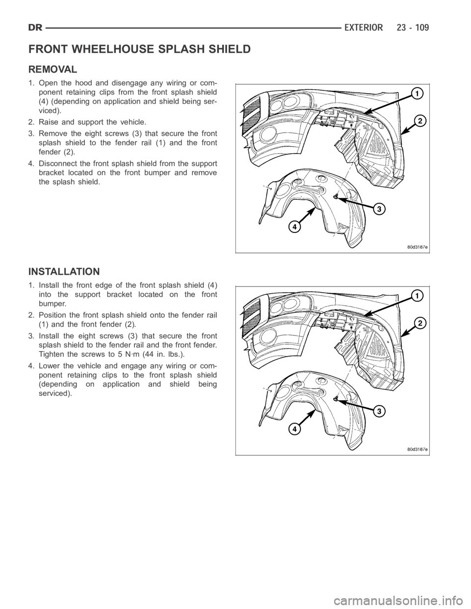
FRONT WHEELHOUSE SPLASH SHIELD
REMOVAL
1. Open the hood and disengage any wiring or com-
ponent retaining clips from the front splash shield
(4) (depending on application and shield being ser-
viced).
2. Raise and support the vehicle.
3. Remove the eight screws (3) that secure the front
splash shield to the fender rail (1) and the front
fender (2).
4. Disconnect the front splash shield from the support
bracket located on the front bumper and remove
the splash shield.
INSTALLATION
1. Install the front edge of the front splash shield (4)
into the support bracket located on the front
bumper.
2. Position the front splash shield onto the fender rail
(1) and the front fender (2).
3. Install the eight screws (3) that secure the front
splash shield to the fender rail and the front fender.
Tighten the screws to 5 Nꞏm (44 in. lbs.).
4. Lower the vehicle and engage any wiring or com-
ponent retaining clips to the front splash shield
(depending on application and shield being
serviced).
Page 4610 of 5267
The motor/module is programmed to learn the speed required to drive the panel based on position and recalibrates
itself as needed. If the sunroof becomes uncalibrated, it will only respond to the vent switch. If the vent switch is
pressed, the glass will move toward vent; if the switch is released, all motion stops. In the event that the sunroof
system becomes uncalibrated performthe sunroof position calibration procedure, (Refer to 8 - ELECTRICAL/
POWER TOP/MOTOR - STANDARD PROCEDURE -SUNROOF POSITION CALIBRATION).
DIAGNOSIS AND TESTING
POWER TOP - SUNROOF
Any diagnosis of the power sunroof system should begin with the use of a scantool and the proper Diagnostic
Procedures Information. The scan tool can provide confirmation that the Controller Area Network (CAN) Data Bus is
functional, that all of the electronic modules are sending and receiving the proper messages on the CAN Data Bus,
and that the power sunroof motor is being sent the proper hard wired output by the sunroof switch.
For complete circuit diagrams, refer to the appropriate wiring information. The wiring information includes wiring dia-
grams, proper wire and connector repair procedures, details of wire harness routing and retention, connector pin-out
information and location views for the various wire harness connectors, splices and grounds.
Refer to the appropriate diagnostic information.
SUNROOF
Refer to SUNROOF DIAGNOSIS CHART for possible causes. Before beginning sunroof diagnostics verify that all
other power accessories are in proper operating condition. If not, a common electrical problem may exist. Refer to
Wiring Diagrams, in this publication for circuit, splice and component descriptions. Check the condition of the circuit
protection (20 amp circuit breaker in the Junction Block). Inspect all wiring connector pins for proper engagement
and continuity. Check for battery voltage at the power sunroof controller, refer to Wiring Diagrams, for circuit infor-
mation. If battery voltage of more than 10 volts is detected at the controller, proceed with the following tests (the
controller will not operate at less than 10 volts).
Before beginning diagnosis for wind noise or water leaks, verify that the problem was not caused by releasing the
control switch before the sunroof was fully closed. The sunroof module hasa water-management system. If how-
ever, the sunroof glass is in a partial closed position, high pressure water may be forced beyond the water man-
agement system boundariesand onto the headlining.
Every time the sunroof module loses power it must be initialized. This is done by connecting power to the sunroof
and moving the sunroof toward the closed position. When initialization occurs a slight “kick” in the sunroof module
will be seen and heard. This is the indication that the sunroof module is initialized
SUNROOF DIAGNOSIS CHART
SYMPTOM POSSIBLE CAUSE
Sunroof motor inoperative. Faulty control switch.
Faulty circuit ground between sunroof module, control switch,
and body harness.
Faulty power circuit between sunroof module, control switch,
and body harness.
Faulty sunroof drive motor.
Faulty sunroof module.
Audible whine when switch is depressed,
sunroof does not operate.Faulty sunroof drive motor.
Binding cable.
Audible clicking or ratcheting when switch is
pressed, sunroof does not operate.Broken or worn drive cable.
Worn drive motor gear.
Mechanisms not synchronized.
Page 4666 of 5267
Low Voltage Interrupt (LVI) Test
If the LVI is suspected to be failing check the following:
1. Check to make sure the battery has 10.5 to 12 volts.
2. If low, charge battery.
3. Wait for 30 seconds or more.
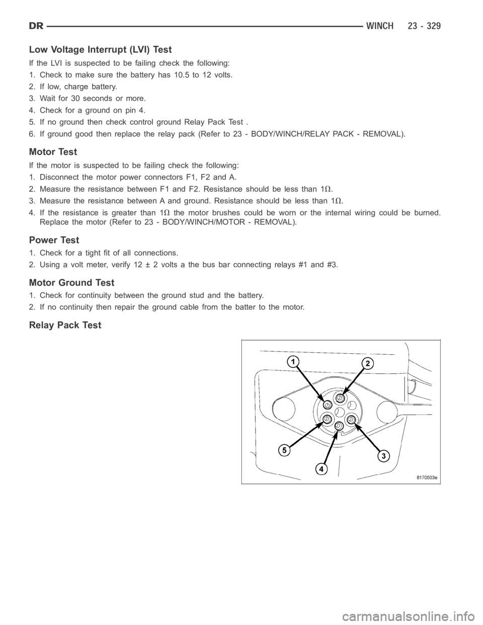
4. Check for a ground on pin 4.
5. If no ground then check control ground Relay Pack Test .
6. If ground good then replace the relay pack (Refer to 23 - BODY/WINCH/RELAYPACK-REMOVAL).
Motor Test
If the motor is suspected to be failing check the following:
1. Disconnect the motor power connectors F1, F2 and A.
2. Measure the resistance between F1 and F2. Resistance should be less than1
.
3. Measure the resistance between A and ground. Resistance should be less than 1
.
4. If the resistance is greater than 1
the motor brushes could be worn or the internal wiring could be burned.
Replace the motor (Refer to 23 - BODY/WINCH/MOTOR - REMOVAL).
Power Test
1. Check for a tight fit of all connections.
2. Using a volt meter, verify 12 ± 2 volts a the bus bar connecting relays #1 and#3.
Motor Ground Test
1. Check for continuity between the ground stud and the battery.
2. If no continuity then repair the ground cable from the batter to the motor.
Relay Pack Test
Page 4732 of 5267
WELD LOCATIONS
SPECIFICATIONS
INDEX
DESCRIPTION FIGURE
FENDER BRACE, CLOSURE TUBE AND FRAME MOUNTING BRACKET TO FRONT
FENDER SUPPORT, FRONT FENDER AND RADIATOR TUBE46
STEERING COLUMN SUPPORT, CONNECTOR WIRING BRACKET AND WELD NUTS
TO LOWER PLENUM PANEL47
WIPER ATTACHING WELD NUTS AND VACUUM RESERVOIR ATTACHING STUDS TO
COWL PAR PANEL48
DASH PANEL TO FRONT FLOOR PAN 49
DASH PANEL TO LOWER PLENUM PANEL 50
LOWER PLENUM PANEL TO COWL BACK PANEL 51
FRONT FENDER AND RADIATOR TUBE DASH PANEL, INSTRUMENT PANEL
MOUNTING BRACKET, AND WELD NUTS TO COWL SIDE PANEL - LEFT SIDE52
DASH PANEL, LOWER PLENUM PANEL AND COWL PANEL BAR TO COWL SIDE
PA N E L - L E F T S I D E53
FRONT FENDER AND RADIATOR TUBE DASH PANEL, INSTRUMENT PANEL
MOUNTING BRACKET AND WELD NUTS TO COWL SIDE PANEL - RIGHT SIDE54
DASH PANEL, LOWER PLENUM PANEL AND COWL PANEL BAR TO COWL SIDE
PANEL - RIGHT SIDE55
REINFORCEMENT AND HEADLAMP MOUNTING PANEL TO OUTER FENDER PANEL 56
SEAT MOUNTING FRONT BRACKETS TO SEAT MOUNTING FRONT CROSSMEMBER
TO FRONT FLOOR PAN57
AIR BAG MODULE BRACKET SHIFTER MOUNTING PLATE AND REAR FLOOR PANEL
TO FRONT FLOOR PAN58
RIGHT TO LEFT REAR FLOOR CROSSMEMBER AND RIGHT TO LEFT SEAT
MOUNTING CROSSMEMBER59
REAR FLOOR CROSSMEMBER, SEAT MOUNTING CROSSMEMBER AND
UNDERBODY SUPPORT TO FLOOR SILL60
SEAT MOUNTING FRONT CROSSMEMBER TO FRONT FLOOR PAN TO UNDERBODY
SUPPORT61
FRONT SEAT MOUNTING CROSSMEMBERS TO FRONT SEAT MOUNTING BRACKET
TO FRONT FLOOR PAN62
REAR FLOOR CROSSMEMBERS TO REAR FLOOR PAN 63
FLOOR SILL TO FRONT SEAT MOUNTING CROSSMEMBER, FRONT AND REAR
FLOOR PAN64
AIR BAG MODULE BRACKET, SHIFTER MOUNTING PLATE AND FRONT SEAT
MOUNTING CROSSMEMBER TO FRONT FLOOR PAN65
REAR SEAT MIDDLE MOUNTING PLATE TO REAR FLOOR PAN TO FRONT FLOOR
PA N66
REAR FLOOR CROSSMEMBER, SEAT MOUNTING CROSSMEMBER AND
UNDERBODY SUPPORT TO FLOOR SILL67
LEFT REAR CROSSMEMBER TO RIGHT REAR CROSSMEMBER TO REAR FLOOR
PA N68
STORAGE BIN TO RIGHT AND LEFT REAR FLOOR CROSSMEMBER TO REAR
FLOOR PAN69