2006 DODGE RAM SRT-10 wiring
[x] Cancel search: wiringPage 4077 of 5267
6.FRONT AXLE DISCONNECT (FAD) MODULE
Using the wiring diagram/schematic as a guide, inspect all wiring and connectors that pertain to this circuit.
Were any problems found?
Ye s>>
Repair as necessary.
Perform the TRANSFER CASE VERIFICATION TEST-VER 1. (Refer to 21 - TRANSMISSION/TRANS-
AXLE/TRANSFER CASE - STANDARD PROCEDURE)
No>>
Replace the Front Axle Disconnect (FAD) Module in accordance with the Service Information.
Perform the TRANSFER CASE VERIFICATION TEST-VER 1. (Refer to 21 - TRANSMISSION/TRANS-
AXLE/TRANSFER CASE - STANDARD PROCEDURE)
7.INTERMITTENT WIRING AND CONNECTORS
The conditions necessary to set this DTC are not present at this time.
Using the schematics as a guide, inspect the wiring and connectors specifictothiscircuit.
Wiggle test the wiring harness and connectors while checking for shorted and open circuits.
Using the scan tool, monitor the data related to this circuit while performing the wiggle test. Look for the data to
change or for the DTC to reset.
Were there any problems found?
Ye s>>
Repair as necessary.
Perform the TRANSFER CASE VERIFICATION TEST-VER 1. (Refer to 21 - TRANSMISSION/TRANS-
AXLE/TRANSFER CASE - STANDARD PROCEDURE)
No>>
Te s t C o m p l e t e .
Page 4078 of 5267
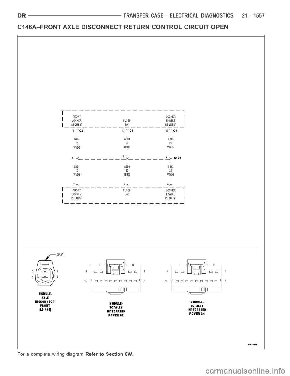
C146A–FRONT AXLE DISCONNECTRETURN CONTROL CIRCUIT OPEN
For a complete wiring diagramRefer to Section 8W.
Page 4082 of 5267
7.FRONT AXLE DISCONNECT (FAD) MODULE
Using the wiring diagram/schematic as a guide, inspect all wiring and connectors that pertain to this circuit.
Were any problems found?
Ye s>>
Repair as necessary.
Perform the TRANSFER CASE VERIFICATION TEST-VER 1. (Refer to 21 - TRANSMISSION/TRANS-
AXLE/TRANSFER CASE - STANDARD PROCEDURE)
No>>
Replace the Front Axle Disconnect (FAD) Module in accordance with the Service Information.
Perform the TRANSFER CASE VERIFICATION TEST-VER 1. (Refer to 21 - TRANSMISSION/TRANS-
AXLE/TRANSFER CASE - STANDARD PROCEDURE)
8.TOTALLY INTEGRATED POWER MODULE (TIPM)
Using the wiring diagram/schematic as a guide, inspect all wiring and connectors that pertain to this circuit.
Were any problems found?
Ye s>>
Repair as necessary.
Perform the TRANSFER CASE VERIFICATION TEST-VER 1. (Refer to 21 - TRANSMISSION/TRANS-
AXLE/TRANSFER CASE - STANDARD PROCEDURE)
No>>
Replace the Totally Integrated Power Module (TIPM) in accordance with theService Information.
Perform the TRANSFER CASE VERIFICATION TEST-VER 1. (Refer to 21 - TRANSMISSION/TRANS-
AXLE/TRANSFER CASE - STANDARD PROCEDURE)
9.INTERMITTENT WIRING AND CONNECTORS
The conditions necessary to set this DTC are not present at this time.
Using the schematics as a guide, inspect the wiring and connectors specifictothiscircuit.
Wiggle test the wiring harness and connectors while checking for shorted and open circuits.
Using the scan tool, monitor the data related to this circuit while performing the wiggle test. Look for the data to
change or for the DTC to reset.
Were there any problems found?
Ye s>>
Repair as necessary.
Perform the TRANSFER CASE VERIFICATION TEST-VER 1. (Refer to 21 - TRANSMISSION/TRANS-
AXLE/TRANSFER CASE - STANDARD PROCEDURE)
No>>
Te s t C o m p l e t e .
STANDARD PROCEDURE
Page 4207 of 5267
REAR EXTENSION
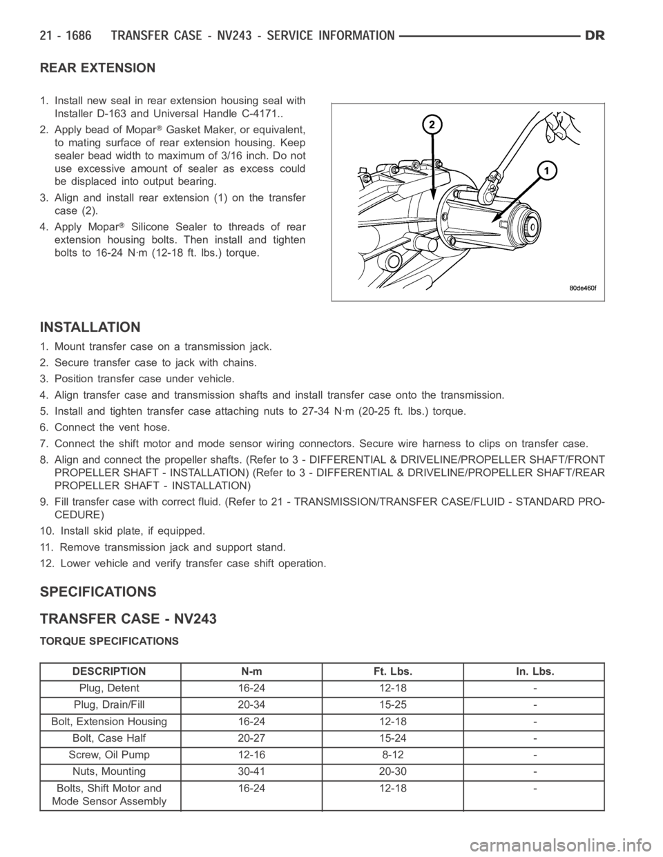
1. Install new seal in rear extension housing seal with
Installer D-163 and Universal Handle C-4171..
2. Apply bead of Mopar
Gasket Maker, or equivalent,
to mating surface of rear extension housing. Keep
sealer bead width to maximum of 3/16 inch. Do not
use excessive amount of sealer as excess could
be displaced into output bearing.
3. Align and install rear extension (1) on the transfer
case (2).
4. Apply Mopar
Silicone Sealer to threads of rear
extension housing bolts. Then install and tighten
bolts to 16-24 Nꞏm (12-18 ft. lbs.) torque.
INSTALLATION
1. Mount transfer case on a transmission jack.
2. Secure transfer case to jack with chains.
3. Position transfer case under vehicle.
4. Align transfer case and transmission shafts and install transfer case onto the transmission.
5. Install and tighten transfer case attaching nuts to 27-34 Nꞏm (20-25 ft.lbs.) torque.
6. Connect the vent hose.
7. Connect the shift motor and mode sensor wiring connectors. Secure wire harness to clips on transfer case.
8. Align and connect the propeller shafts. (Refer to 3 - DIFFERENTIAL & DRIVELINE/PROPELLER SHAFT/FRONT
PROPELLER SHAFT - INSTALLATION) (Refer to 3 - DIFFERENTIAL & DRIVELINE/PROPELLER SHAFT/REAR
PROPELLER SHAFT - INSTALLATION)
9. Fill transfer case with correct fluid. (Refer to 21 - TRANSMISSION/TRANSFER CASE/FLUID - STANDARD PRO-
CEDURE)
10. Install skid plate, if equipped.
11. Remove transmission jack and support stand.
12. Lower vehicle and verify transfer case shift operation.
SPECIFICATIONS
TRANSFER CASE - NV243
TORQUE SPECIFICATIONS
DESCRIPTION N-m Ft. Lbs. In. Lbs.
Plug, Detent 16-24 12-18 -
Plug, Drain/Fill 20-34 15-25 -
Bolt, Extension Housing 16-24 12-18 -
Bolt, Case Half 20-27 15-24 -
Screw, Oil Pump 12-16 8-12 -
Nuts, Mounting 30-41 20-30 -
Bolts, Shift Motor and
Mode Sensor Assembly16-24 12-18 -
Page 4218 of 5267
MOTOR-SHIFT
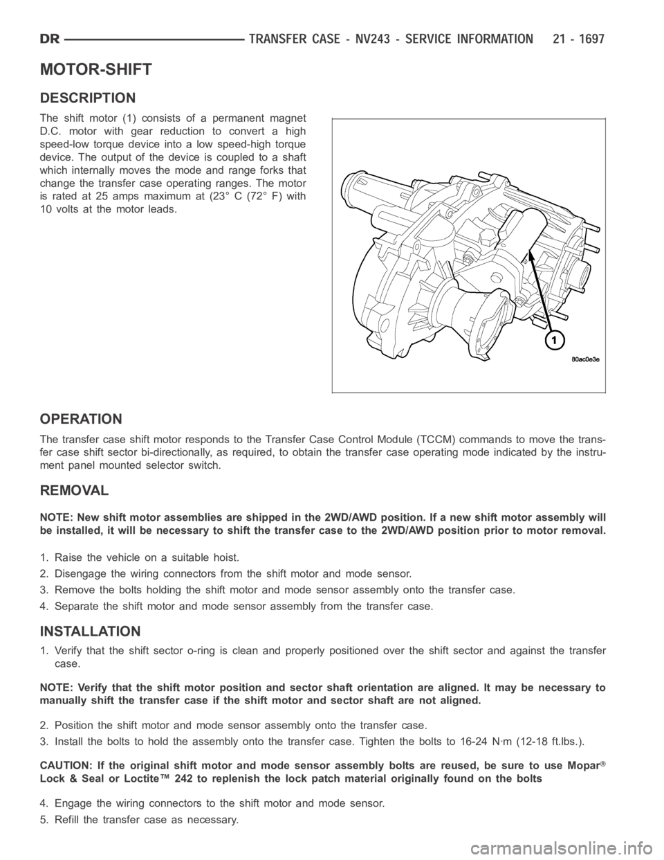
DESCRIPTION
The shift motor (1) consists of a permanent magnet
D.C. motor with gear reduction to convert a high
speed-low torque device into a low speed-high torque
device. The output of the device is coupled to a shaft
which internally moves the mode and range forks that
change the transfer case operating ranges. The motor
is rated at 25 amps maximum at (23° C (72° F) with
10 volts at the motor leads.
OPERATION
The transfer case shift motor responds to the Transfer Case Control Module(TCCM) commands to move the trans-
fer case shift sector bi-directionally, as required, to obtain the transfer case operating mode indicated by the instru-
ment panel mounted selector switch.
REMOVAL
NOTE: New shift motor assemblies are shipped in the 2WD/AWD position. If a new shift motor assembly will
be installed, it will be necessary to shift the transfer case to the 2WD/AWDposition prior to motor removal.
1. Raise the vehicle on a suitable hoist.
2. Disengage the wiring connectors from the shift motor and mode sensor.
3. Remove the bolts holding the shift motor and mode sensor assembly onto the transfer case.
4. Separate the shift motor and mode sensor assembly from the transfer case.
INSTALLATION
1. Verify that the shift sector o-ring is clean and properly positioned over the shift sector and against the transfer
case.
NOTE: Verify that the shift motor position and sector shaft orientation are aligned. It may be necessary to
manually shift the transfer case if the shift motor and sector shaft are notaligned.
2. Position the shift motor and mode sensor assembly onto the transfer case.
3. Install the bolts to hold the assembly onto the transfer case. Tighten the bolts to 16-24 Nꞏm (12-18 ft.lbs.).
CAUTION: If the original shift motor and mode sensor assembly bolts are reused, be sure to use Mopar
Lock & Seal or Loctite™ 242 to replenish the lock patch material originallyfound on the bolts
4. Engage the wiring connectors to the shift motor and mode sensor.
5. Refill the transfer case as necessary.
Page 4251 of 5267

REAR EXTENSION
1. Install new seal in rear extension housing seal with
Seal Installer D-163 and Universal Handle C-4171.
Verify that the weep hole in the rubber is oriented
downward.
2. Apply bead of Mopar
Gasket Maker, or equivalent,
to mating surface of rear extension housing. Keep
sealer bead width to maximum of 3/16 inch. Do not
use excessive amount of sealer as excess could
be displaced into output bearing.
3. Align and install rear extension (1) on the transfer
case (2).
4. Apply Mopar
Silicone Sealer to threads of rear
extension housing bolts. Then install and tighten
bolts to 16-24 Nꞏm (12-18 ft. lbs.) torque.
INSTALLATION
1. Mount transfer case on a transmission jack.
2. Secure transfer case to jack with chains.
3. Position transfer case under vehicle.
4. Align transfer case and transmission shafts and install transfer case onto the transmission.
5. Install and tighten transfer case attaching nuts to 27-34 Nꞏm (20-25 ft.lbs.) torque.
6. Connect the vent hose.
7. Connect the shift motor and mode sensor wiring connectors. Secure wire harness to clips on transfer case.
8. Align and connect the propeller shafts. (Refer to 3 - DIFFERENTIAL & DRIVELINE/PROPELLER SHAFT/FRONT
PROPELLER SHAFT - INSTALLATION) (Refer to 3 - DIFFERENTIAL & DRIVELINE/PROPELLER SHAFT/REAR
PROPELLER SHAFT - INSTALLATION)
9. Fill transfer case with correct fluid. (Refer to 21 - TRANSMISSION/TRANSFER CASE/FLUID - STANDARD PRO-
CEDURE)
10. Install skid plate, if equipped.
11. Remove transmission jack and support stand.
12. Lower vehicle and verify transfer case shift operation.
SPECIFICATIONS
TRANSFER CASE - NV244 GENII
TORQUE SPECIFICATIONS
DESCRIPTION N-m Ft. Lbs. In. Lbs.
Plug, Detent 16-24 12-18 -
Plug, Drain/Fill 20-34 15-25 -
Bolt, Extension Housing 16-24 12-18 -
Bolt, Case Half 25-28 18-21 -
Screw, Oil Pump 14-19 10-14 -
Nuts, Mounting 30-41 20-30 -
Bolts, Shift Motor and
Mode Sensor Assembly16-24 12-18 -
Page 4262 of 5267
MOTOR-SHIFT
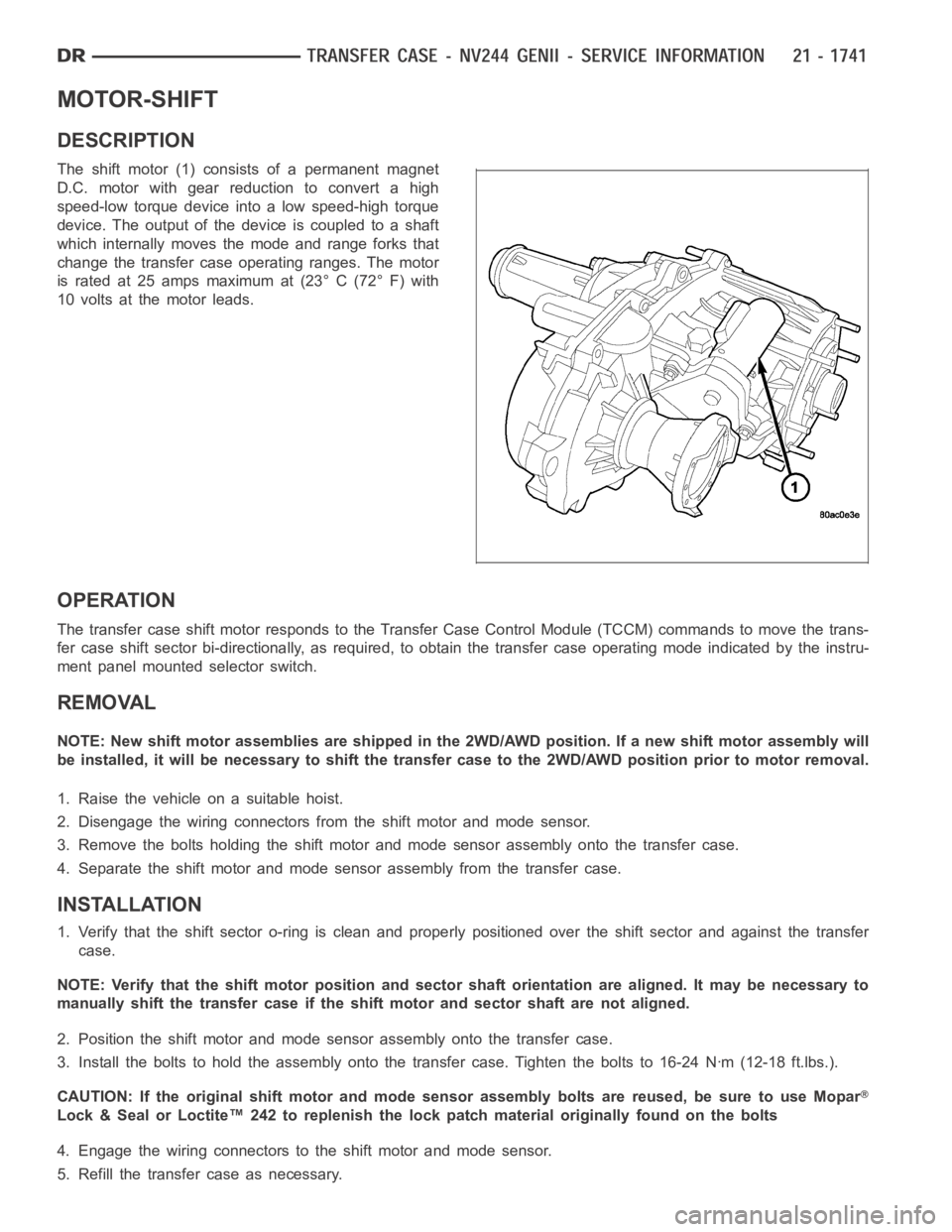
DESCRIPTION
The shift motor (1) consists of a permanent magnet
D.C. motor with gear reduction to convert a high
speed-low torque device into a low speed-high torque
device. The output of the device is coupled to a shaft
which internally moves the mode and range forks that
change the transfer case operating ranges. The motor
is rated at 25 amps maximum at (23° C (72° F) with
10 volts at the motor leads.
OPERATION
The transfer case shift motor responds to the Transfer Case Control Module(TCCM) commands to move the trans-
fer case shift sector bi-directionally, as required, to obtain the transfer case operating mode indicated by the instru-
ment panel mounted selector switch.
REMOVAL
NOTE: New shift motor assemblies are shipped in the 2WD/AWD position. If a new shift motor assembly will
be installed, it will be necessary to shift the transfer case to the 2WD/AWDposition prior to motor removal.
1. Raise the vehicle on a suitable hoist.
2. Disengage the wiring connectors from the shift motor and mode sensor.
3. Remove the bolts holding the shift motor and mode sensor assembly onto the transfer case.
4. Separate the shift motor and mode sensor assembly from the transfer case.
INSTALLATION
1. Verify that the shift sector o-ring is clean and properly positioned over the shift sector and against the transfer
case.
NOTE: Verify that the shift motor position and sector shaft orientation are aligned. It may be necessary to
manually shift the transfer case if the shift motor and sector shaft are notaligned.
2. Position the shift motor and mode sensor assembly onto the transfer case.
3. Install the bolts to hold the assembly onto the transfer case. Tighten the bolts to 16-24 Nꞏm (12-18 ft.lbs.).
CAUTION: If the original shift motor and mode sensor assembly bolts are reused, be sure to use Mopar
Lock & Seal or Loctite™ 242 to replenish the lock patch material originallyfound on the bolts
4. Engage the wiring connectors to the shift motor and mode sensor.
5. Refill the transfer case as necessary.
Page 4301 of 5267
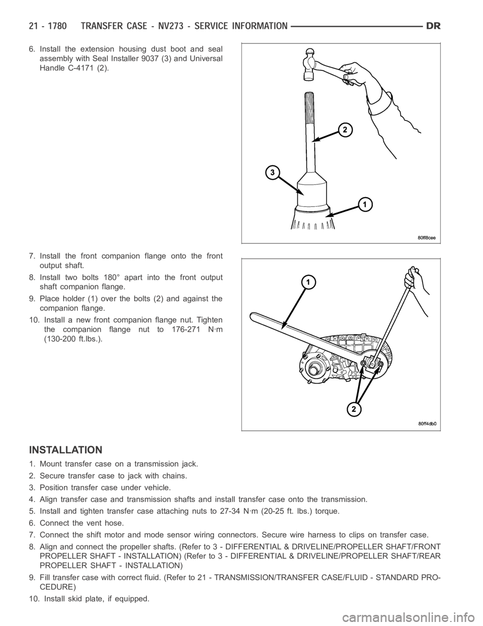
6. Install the extension housing dust boot and seal
assembly with Seal Installer 9037 (3) and Universal
Handle C-4171 (2).
7. Install the front companion flange onto the front
output shaft.
8. Install two bolts 180° apart into the front output
shaft companion flange.
9. Place holder (1) over the bolts (2) and against the
companion flange.
10. Install a new front companion flange nut. Tighten
the companion flange nut to 176-271 Nꞏm
(130-200 ft.lbs.).
INSTALLATION
1. Mount transfer case on a transmission jack.
2. Secure transfer case to jack with chains.
3. Position transfer case under vehicle.
4. Align transfer case and transmission shafts and install transfer case onto the transmission.
5. Install and tighten transfer case attaching nuts to 27-34 Nꞏm (20-25 ft.lbs.) torque.
6. Connect the vent hose.
7. Connect the shift motor and mode sensor wiring connectors. Secure wire harness to clips on transfer case.
8. Align and connect the propeller shafts. (Refer to 3 - DIFFERENTIAL & DRIVELINE/PROPELLER SHAFT/FRONT
PROPELLER SHAFT - INSTALLATION) (Refer to 3 - DIFFERENTIAL & DRIVELINE/PROPELLER SHAFT/REAR
PROPELLER SHAFT - INSTALLATION)
9. Fill transfer case with correct fluid. (Refer to 21 - TRANSMISSION/TRANSFER CASE/FLUID - STANDARD PRO-
CEDURE)
10. Install skid plate, if equipped.