Page 3967 of 5267
3. Install the TRS (3) into the mounting bracket (2)
with the wiring connector facing the front of the
transmission.
4. Install the two screws to hold the TRS to the
mounting bracket. Tighten the screws to 5 Nꞏm (45
in.lbs.).
5. Verify proper sensor operation (1-4).
6. Move the transmission manual shaft lever to the
PARK position.
7. Connect TRS wiring connector to the TRS and
lower vehicle.
8. Refill the transmission fluid to the correct level.
1 - NEUTRAL CONTACT
2 - MANUAL LEVER AND SENSOR PLUNGER IN REVERSE
POSITION
3 - PARK CONTACT
4 - TRANSMISSION RANGE SENSOR
Page 4022 of 5267
C1401- TRANSFER CASE RANGE SELECT SWITCH CIRCUIT LOW
For a complete wiring diagramRefer to Section 8W
Page 4026 of 5267

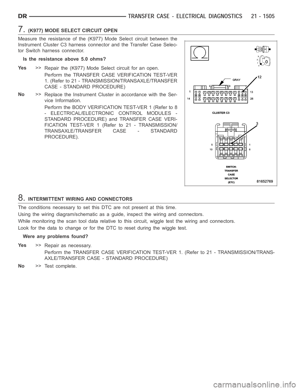
7.(K977) MODE SELECT CIRCUIT OPEN
Measure the resistance of the (K977) Mode Select circuit between the
Instrument Cluster C3 harness connector and the Transfer Case Selec-
tor Switch harness connector.
Is the resistance above 5.0 ohms?
Ye s>>
Repair the (K977) Mode Select circuit for an open.
Perform the TRANSFER CASE VERIFICATION TEST-VER
1. (Refer to 21 - TRANSMISSION/TRANSAXLE/TRANSFER
CASE - STANDARD PROCEDURE)
No>>
Replace the Instrument Cluster in accordance with the Ser-
vice Information.
Perform the BODY VERIFICATION TEST-VER 1 (Refer to 8
- ELECTRICAL/ELECTRONIC CONTROL MODULES -
STANDARD PROCEDURE) and TRANSFER CASE VERI-
FICATION TEST-VER 1 (Refer to 21 - TRANSMISSION/
TRANSAXLE/TRANSFER CASE - STANDARD
PROCEDURE).
8.INTERMITTENT WIRING AND CONNECTORS
The conditions necessary to set this DTC are not present at this time.
Using the wiring diagram/schematic as a guide, inspect the wiring and connectors.
While monitoring the scan tool data relative to this circuit, wiggle test the wiring and connectors.
Look for the data to change or for the DTC to reset during the wiggle test.
Were any problems found?
Ye s>>
Repair as necessary.
Perform the TRANSFER CASE VERIFICATION TEST-VER 1. (Refer to 21 - TRANSMISSION/TRANS-
AXLE/TRANSFER CASE - STANDARD PROCEDURE)
No>>
Te s t c o m p l e t e .
Page 4027 of 5267
C1402- TRANSFER CASE RANGE SELECT SWITCH CIRCUIT HIGH
For a complete wiring diagramRefer to Section 8W
Page 4031 of 5267
7.INSTRUMENT CLUSTER
Repair
Replace the Instrument Cluster in accordance with the Service Information.
Perform the BODY VERIFICATION TEST-VER 1 (Refer to 8 - ELECTRICAL/ELECTRONIC CONTROL
MODULES - STANDARD PROCEDURE) and TRANSFER CASE VERIFICATION TEST-VER 1 (Refer to
21 - TRANSMISSION/TRANSAXLE/TRANSFER CASE - STANDARD PROCEDURE).
8.INTERMITTENT WIRING AND CONNECTORS
The conditions necessary to set this DTC are not present at this time.
Using the wiring diagram/schematic as a guide, inspect the wiring and connectors.
While monitoring the scan tool data relative to this circuit, wiggle test the wiring and connectors.
Look for the data to change or for the DTC to reset during the wiggle test.
Were any problems found?
Ye s>>
Repair as necessary.
Perform the TRANSFER CASE VERIFICATION TEST-VER 1. (Refer to 21 - TRANSMISSION/TRANS-
AXLE/TRANSFER CASE - STANDARD PROCEDURE)
No>>
Te s t c o m p l e t e .
Page 4032 of 5267
C1404- TRANSFER CASE RANGE POSITION SENSOR CIRCUIT LOW
For a complete wiring diagramRefer to Section 8W
Page 4035 of 5267

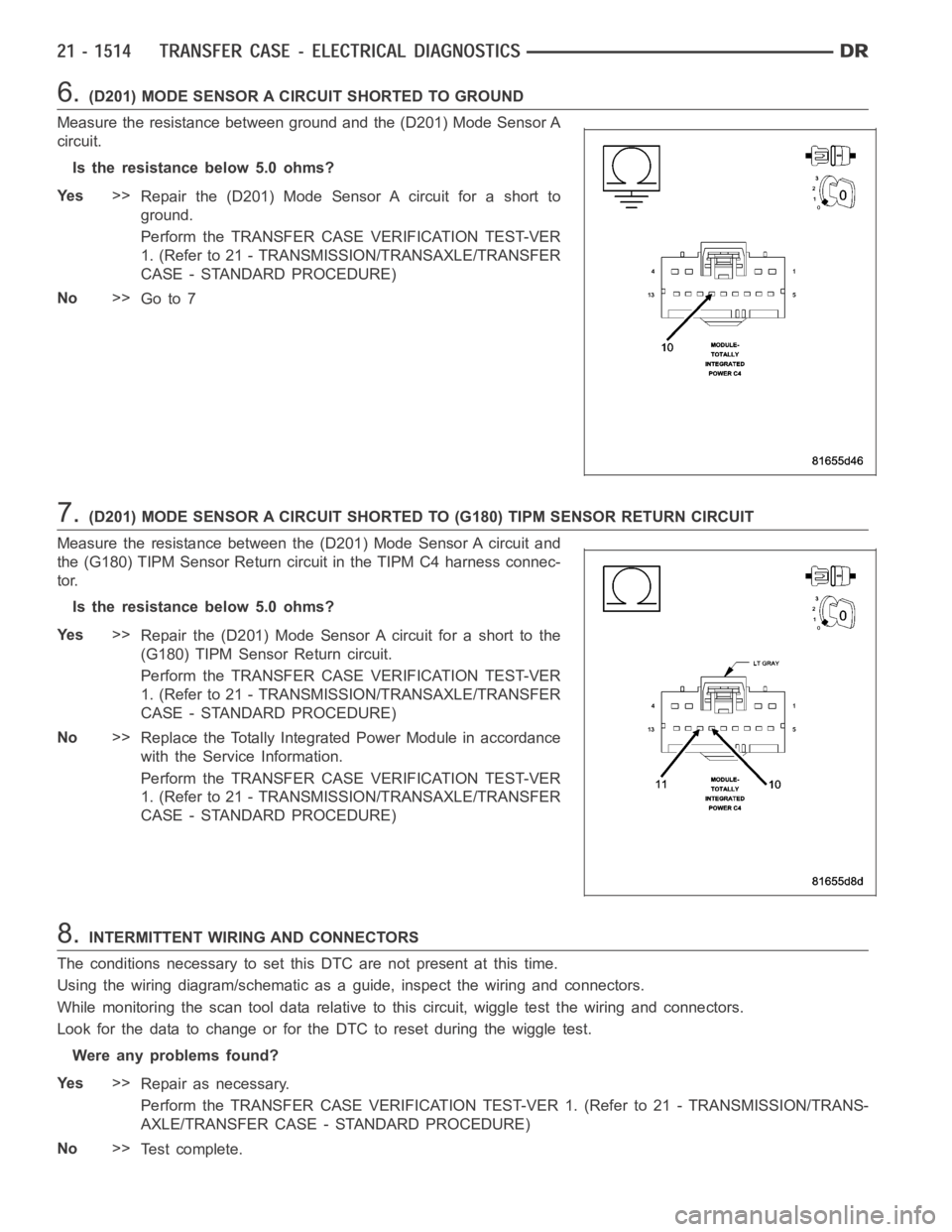
6.(D201) MODE SENSOR A CIRCUIT SHORTED TO GROUND
Measure the resistance between ground and the (D201) Mode Sensor A
circuit.
Is the resistance below 5.0 ohms?
Ye s>>
Repair the (D201) Mode Sensor A circuit for a short to
ground.
Perform the TRANSFER CASE VERIFICATION TEST-VER
1. (Refer to 21 - TRANSMISSION/TRANSAXLE/TRANSFER
CASE - STANDARD PROCEDURE)
No>>
Go to 7
7.(D201) MODE SENSOR A CIRCUIT SHORTED TO (G180) TIPM SENSOR RETURN CIRCUIT
Measure the resistance between the (D201) Mode Sensor A circuit and
the (G180) TIPM Sensor Return circuit in the TIPM C4 harness connec-
tor.
Is the resistance below 5.0 ohms?
Ye s>>
Repair the (D201) Mode Sensor A circuit for a short to the
(G180) TIPM Sensor Return circuit.
Perform the TRANSFER CASE VERIFICATION TEST-VER
1. (Refer to 21 - TRANSMISSION/TRANSAXLE/TRANSFER
CASE - STANDARD PROCEDURE)
No>>
Replace the Totally Integrated Power Module in accordance
with the Service Information.
Perform the TRANSFER CASE VERIFICATION TEST-VER
1. (Refer to 21 - TRANSMISSION/TRANSAXLE/TRANSFER
CASE - STANDARD PROCEDURE)
8.INTERMITTENT WIRING AND CONNECTORS
The conditions necessary to set this DTC are not present at this time.
Using the wiring diagram/schematic as a guide, inspect the wiring and connectors.
While monitoring the scan tool data relative to this circuit, wiggle test the wiring and connectors.
Look for the data to change or for the DTC to reset during the wiggle test.
Were any problems found?
Ye s>>
Repair as necessary.
Perform the TRANSFER CASE VERIFICATION TEST-VER 1. (Refer to 21 - TRANSMISSION/TRANS-
AXLE/TRANSFER CASE - STANDARD PROCEDURE)
No>>
Te s t c o m p l e t e .
Page 4036 of 5267
C1405- TRANSFER CASE RANGE POSITION SENSOR CIRCUIT HIGH
For a complete wiring diagramRefer to Section 8W