2006 DODGE RAM SRT-10 wiring
[x] Cancel search: wiringPage 3782 of 5267
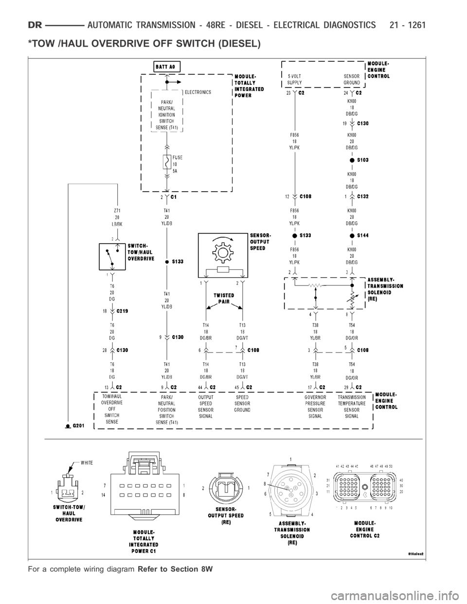
*TOW /HAUL OVERDRIVE OFF SWITCH (DIESEL)
For a complete wiring diagramRefer to Section 8W
Page 3786 of 5267
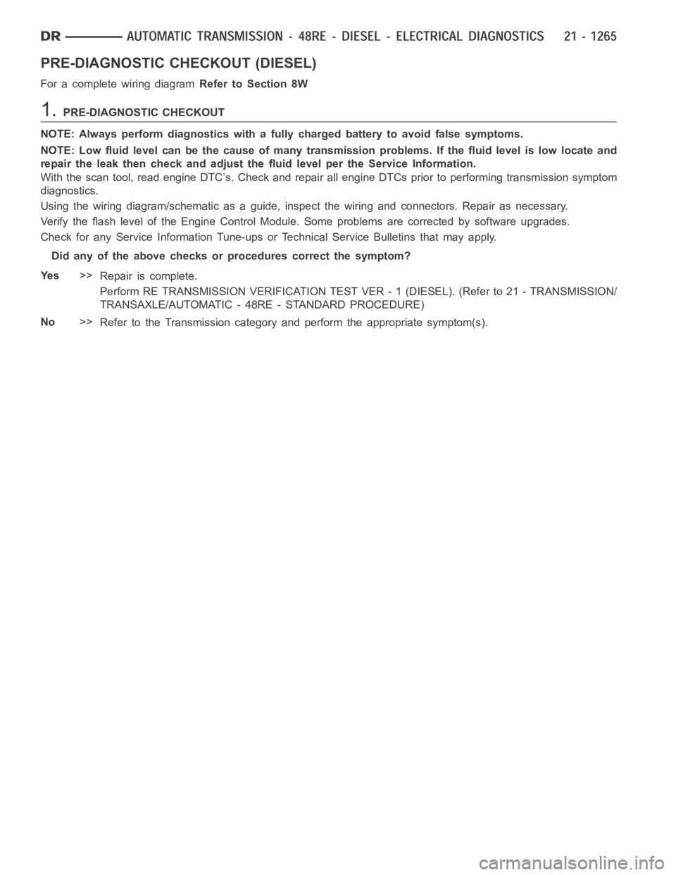
PRE-DIAGNOSTIC CHECKOUT (DIESEL)
For a complete wiring diagramRefer to Section 8W
1.PRE-DIAGNOSTIC CHECKOUT
NOTE: Always perform diagnostics with a fully charged battery to avoid false symptoms.
NOTE: Low fluid level can be the cause of many transmission problems. If thefluid level is low locate and
repair the leak then check and adjust the fluid level per the Service Information.
With the scan tool, read engine DTC’s. Check and repair all engine DTCs prior to performing transmission symptom
diagnostics.
Using the wiring diagram/schematic as a guide, inspect the wiring and connectors. Repair as necessary.
Verify the flash level of the Engine Control Module. Some problems are corrected by software upgrades.
Check for any Service Information Tune-ups or Technical Service Bulletins that may apply.
Did any of the above checks or procedures correct the symptom?
Ye s>>
Repair is complete.
Perform RE TRANSMISSION VERIFICATION TEST VER - 1 (DIESEL). (Refer to 21 - TRANSMISSION/
TRANSAXLE/AUTOMATIC - 48RE - STANDARD PROCEDURE)
No>>
Refer to the Transmission category and perform the appropriate symptom(s).
Page 3799 of 5267
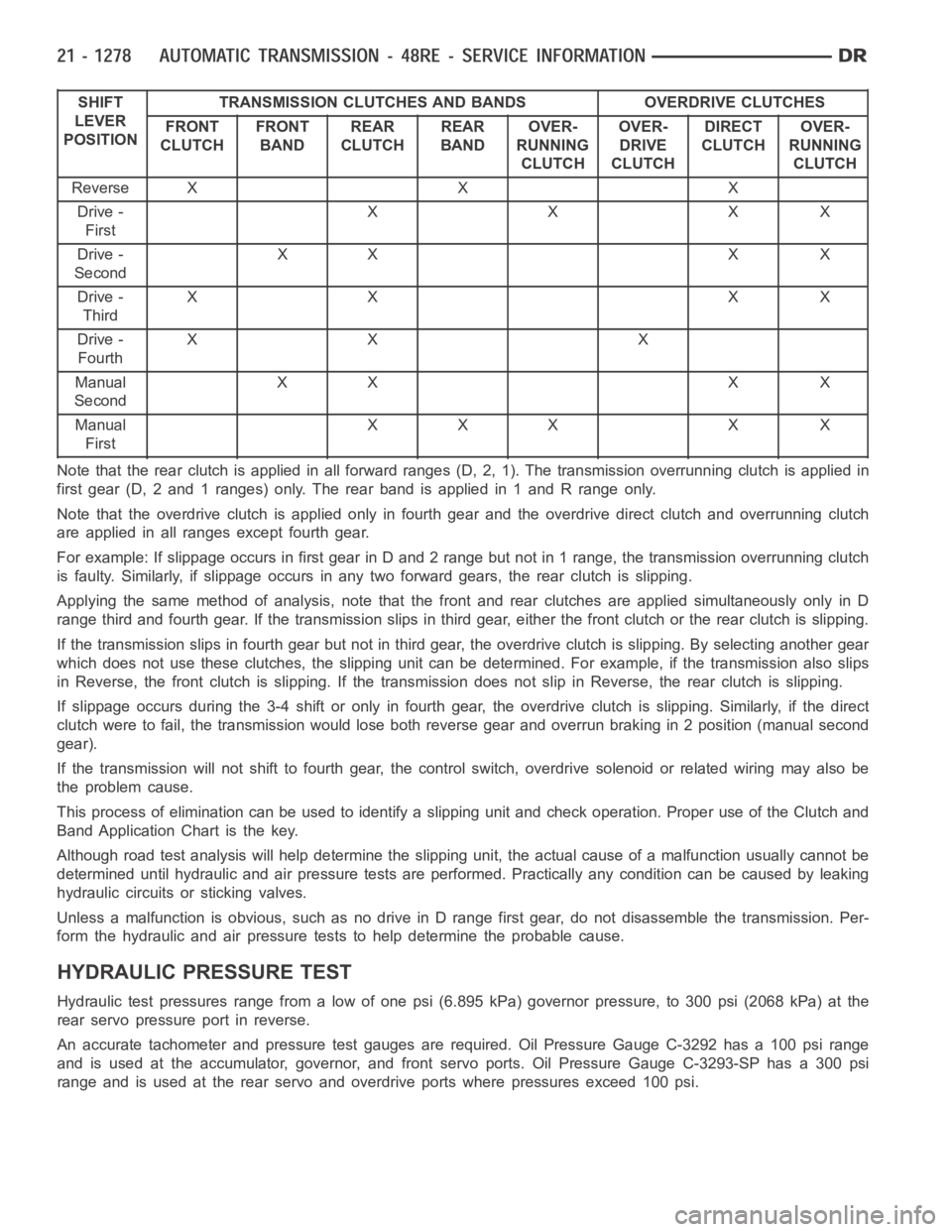
SHIFT
LEVER
POSITIONTRANSMISSION CLUTCHES AND BANDS OVERDRIVE CLUTCHES
FRONT
CLUTCHFRONT
BANDREAR
CLUTCHREAR
BANDOVER-
RUNNING
CLUTCHOVER-
DRIVE
CLUTCHDIRECT
CLUTCHOVER-
RUNNING
CLUTCH
ReverseXXX
Drive -
FirstXXXX
Drive -
SecondXX X X
Drive -
ThirdXX XX
Drive -
FourthXX X
Manual
SecondXX X X
Manual
FirstXXX X X
Note that the rear clutch is applied in all forward ranges (D, 2, 1). The transmission overrunning clutch is applied in
first gear (D, 2 and 1 ranges) only. The rear band is applied in 1 and R range only.
Note that the overdrive clutch is applied only in fourth gear and the overdrive direct clutch and overrunning clutch
are applied in all ranges except fourth gear.
For example: If slippage occurs in first gear in D and 2 range but not in 1 range, the transmission overrunning clutch
is faulty. Similarly, if slippage occurs in any two forward gears, the rearclutch is slipping.
Applying the same method of analysis, note that the front and rear clutchesare applied simultaneously only in D
range third and fourth gear. If the transmission slips in third gear, either the front clutch or the rear clutch is slipping.
Ifthetransmissionslipsinfourthgearbutnotinthirdgear,theoverdrive clutch is slipping. By selecting another gear
which does not use these clutches, the slipping unit can be determined. Forexample, if the transmission also slips
in Reverse, the front clutch is slipping. If the transmission does not slipin Reverse, the rear clutch is slipping.
If slippage occurs during the 3-4 shift or only in fourth gear, the overdrive clutch is slipping. Similarly, if the direct
clutch were to fail, the transmission would lose both reverse gear and overrun braking in 2 position (manual second
gear).
If the transmission will not shift to fourth gear, the control switch, overdrive solenoid or related wiring may also be
the problem cause.
This process of elimination can be used to identify a slipping unit and check operation. Proper use of the Clutch and
Band Application Chart is the key.
Although road test analysis will help determine the slipping unit, the actual cause of a malfunction usually cannot be
determined until hydraulic and air pressure tests are performed. Practically any condition can be caused by leaking
hydraulic circuits or sticking valves.
Unless a malfunction is obvious, such as no drive in D range first gear, do not disassemble the transmission. Per-
form the hydraulic and air pressure tests to help determine the probable cause.
HYDRAULIC PRESSURE TEST
Hydraulic test pressures range from a low of one psi (6.895 kPa) governor pressure, to 300 psi (2068 kPa) at the
rear servo pressure port in reverse.
An accurate tachometer and pressure test gauges are required. Oil Pressure Gauge C-3292 has a 100 psi range
and is used at the accumulator, governor, and front servo ports. Oil Pressure Gauge C-3293-SP has a 300 psi
range and is used at the rear servo and overdrive ports where pressures exceed 100 psi.
Page 3810 of 5267
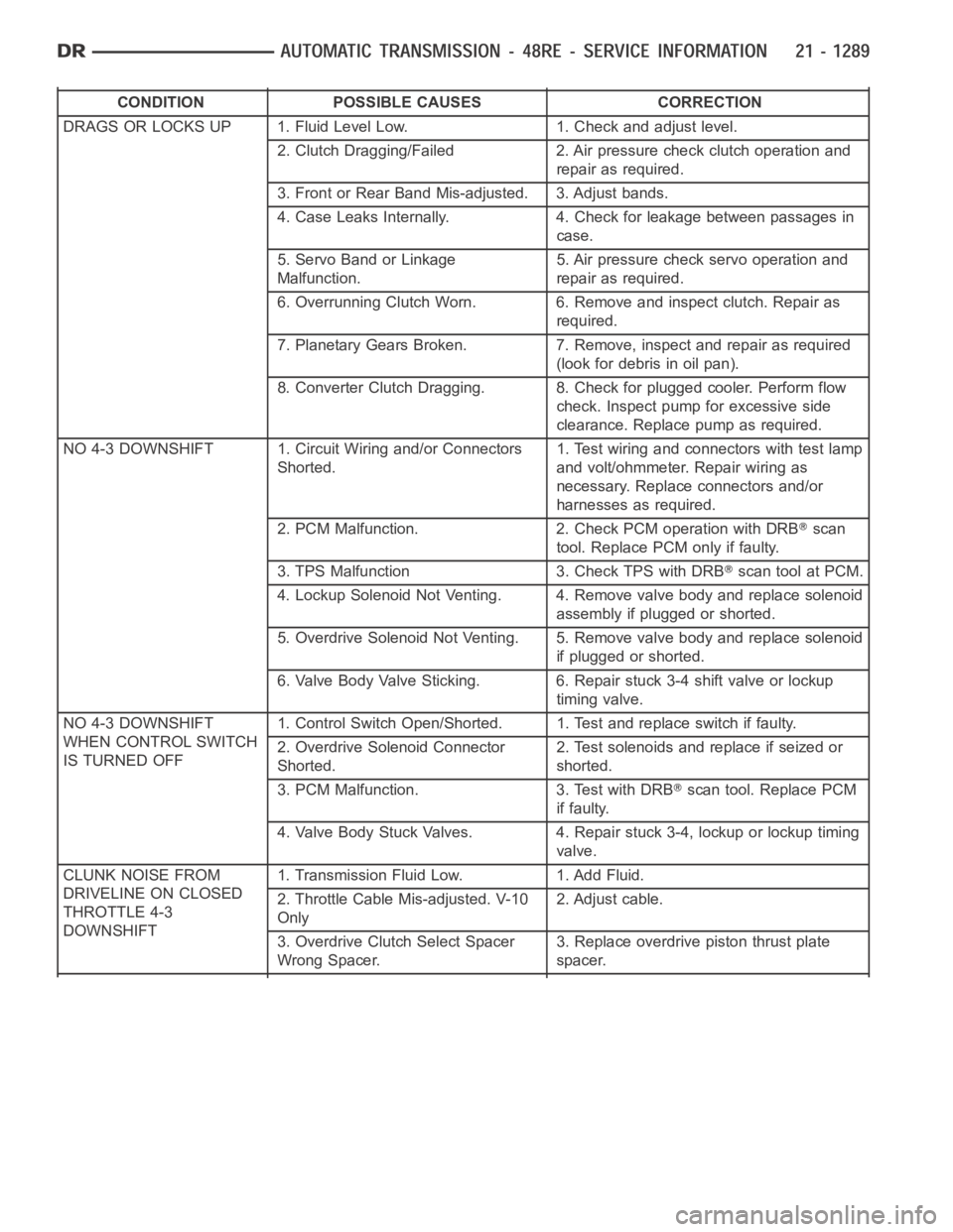
CONDITION POSSIBLE CAUSES CORRECTION
DRAGS OR LOCKS UP 1. Fluid Level Low. 1. Check and adjust level.
2. Clutch Dragging/Failed 2. Air pressure check clutch operation and
repair as required.
3. Front or Rear Band Mis-adjusted. 3. Adjust bands.
4. Case Leaks Internally. 4. Check for leakage between passages in
case.
5. Servo Band or Linkage
Malfunction.5. Air pressure check servo operation and
repair as required.
6. Overrunning Clutch Worn. 6. Remove and inspect clutch. Repair as
required.
7. Planetary Gears Broken. 7. Remove, inspect and repair as required
(look for debris in oil pan).
8. Converter Clutch Dragging. 8. Check for plugged cooler. Perform flow
check. Inspect pump for excessive side
clearance. Replace pump as required.
NO 4-3 DOWNSHIFT 1. Circuit Wiring and/or Connectors
Shorted.1. Test wiring and connectors with test lamp
and volt/ohmmeter. Repair wiring as
necessary. Replace connectors and/or
harnesses as required.
2. PCM Malfunction. 2. Check PCM operation with DRB
scan
tool. Replace PCM only if faulty.
3. TPS Malfunction 3. Check TPS with DRB
scan tool at PCM.
4. Lockup Solenoid Not Venting. 4. Remove valve body and replace solenoid
assembly if plugged or shorted.
5. Overdrive Solenoid Not Venting. 5. Remove valve body and replace solenoid
if plugged or shorted.
6. Valve Body Valve Sticking. 6. Repair stuck 3-4 shift valve or lockup
timing valve.
NO 4-3 DOWNSHIFT
WHEN CONTROL SWITCH
IS TURNED OFF1. Control Switch Open/Shorted. 1. Test and replace switch if faulty.
2. Overdrive Solenoid Connector
Shorted.2. Test solenoids and replace if seized or
shorted.
3. PCM Malfunction. 3. Test with DRB
scan tool. Replace PCM
if faulty.
4. Valve Body Stuck Valves. 4. Repair stuck 3-4, lockup or lockup timing
valve.
CLUNK NOISE FROM
DRIVELINE ON CLOSED
THROTTLE 4-3
DOWNSHIFT1. Transmission Fluid Low. 1. Add Fluid.
2. Throttle Cable Mis-adjusted. V-10
Only2. Adjust cable.
3. Overdrive Clutch Select Spacer
Wrong Spacer.3. Replace overdrive piston thrust plate
spacer.
Page 3811 of 5267
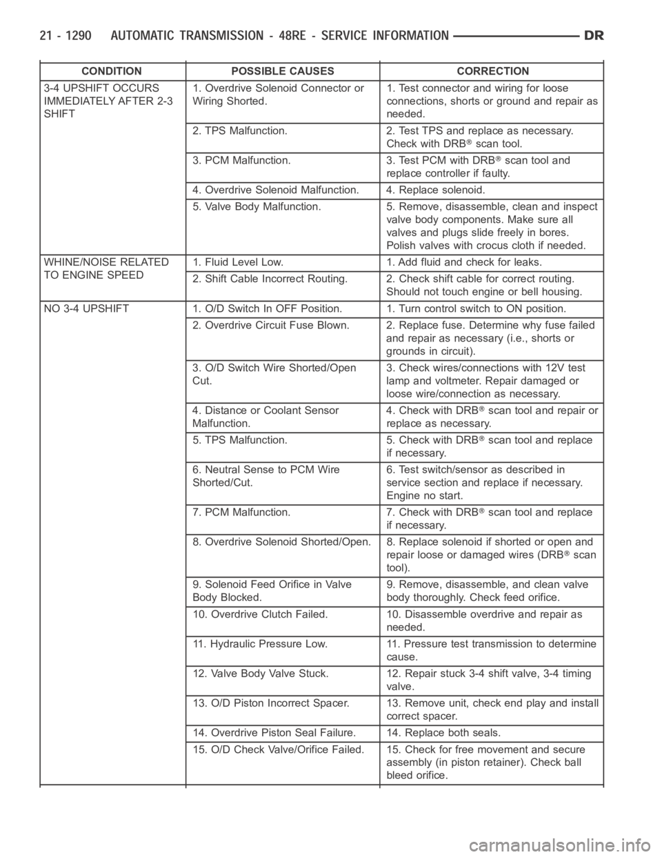
CONDITION POSSIBLE CAUSES CORRECTION
3-4 UPSHIFT OCCURS
IMMEDIATELY AFTER 2-3
SHIFT1. Overdrive Solenoid Connector or
Wiring Shorted.1. Test connector and wiring for loose
connections, shorts or ground and repair as
needed.
2. TPS Malfunction. 2. Test TPS and replace as necessary.
Check with DRB
scan tool.
3. PCM Malfunction. 3. Test PCM with DRB
scan tool and
replace controller if faulty.
4. Overdrive Solenoid Malfunction. 4. Replace solenoid.
5. Valve Body Malfunction. 5. Remove, disassemble, clean and inspect
valve body components. Make sure all
valves and plugs slide freely in bores.
Polish valves with crocus cloth if needed.
WHINE/NOISE RELATED
TO ENGINE SPEED1. Fluid Level Low. 1. Add fluid and check for leaks.
2. Shift Cable Incorrect Routing. 2. Check shift cable for correct routing.
Should not touch engine or bell housing.
NO3-4UPSHIFT 1.O/DSwitchInOFFPosition. 1.TurncontrolswitchtoONposition.
2. Overdrive Circuit Fuse Blown. 2. Replace fuse. Determine why fuse failed
and repair as necessary (i.e., shorts or
grounds in circuit).
3. O/D Switch Wire Shorted/Open
Cut.3. Check wires/connections with 12V test
lamp and voltmeter. Repair damaged or
loose wire/connection as necessary.
4. Distance or Coolant Sensor
Malfunction.4. Check with DRB
scan tool and repair or
replace as necessary.
5. TPS Malfunction. 5. Check with DRB
scan tool and replace
if necessary.
6. Neutral Sense to PCM Wire
Shorted/Cut.6. Test switch/sensor as described in
service section and replace if necessary.
Engine no start.
7. PCM Malfunction. 7. Check with DRB
scan tool and replace
if necessary.
8. Overdrive Solenoid Shorted/Open. 8. Replace solenoid if shorted or openand
repair loose or damaged wires (DRB
scan
tool).
9. Solenoid Feed Orifice in Valve
Body Blocked.9. Remove, disassemble, and clean valve
body thoroughly. Check feed orifice.
10. Overdrive Clutch Failed. 10. Disassemble overdrive and repair as
needed.
11. Hydraulic Pressure Low. 11. Pressure test transmission to determine
cause.
12. Valve Body Valve Stuck. 12. Repair stuck 3-4 shift valve, 3-4 timing
valve.
13. O/D Piston Incorrect Spacer. 13. Remove unit, check end play and install
correct spacer.
14. Overdrive Piston Seal Failure. 14. Replace both seals.
15. O/D Check Valve/Orifice Failed. 15. Check for free movement and secure
assembly (in piston retainer). Check ball
bleed orifice.
Page 3812 of 5267
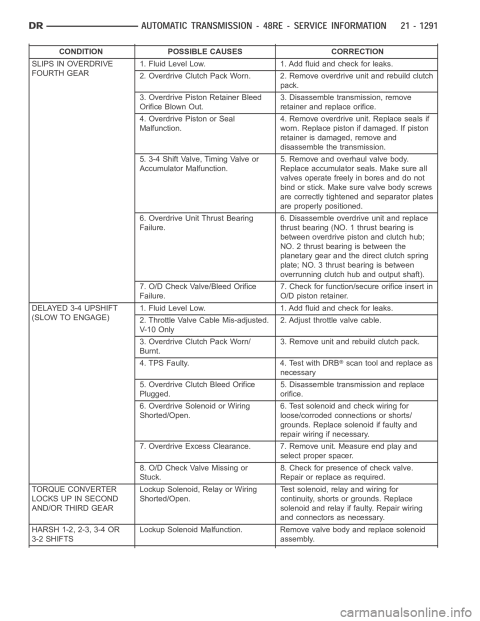
CONDITION POSSIBLE CAUSES CORRECTION
SLIPS IN OVERDRIVE
FOURTH GEAR1. Fluid Level Low. 1. Add fluid and check for leaks.
2. Overdrive Clutch Pack Worn. 2. Remove overdrive unit and rebuild clutch
pack.
3. Overdrive Piston Retainer Bleed
Orifice Blown Out.3. Disassemble transmission, remove
retainer and replace orifice.
4. Overdrive Piston or Seal
Malfunction.4. Remove overdrive unit. Replace seals if
worn. Replace piston if damaged. If piston
retainer is damaged, remove and
disassemble the transmission.
5. 3-4 Shift Valve, Timing Valve or
Accumulator Malfunction.5. Remove and overhaul valve body.
Replace accumulator seals. Make sure all
valves operate freely in bores and do not
bind or stick. Make sure valve body screws
are correctly tightened and separator plates
are properly positioned.
6. Overdrive Unit Thrust Bearing
Failure.6. Disassemble overdrive unit and replace
thrust bearing (NO. 1 thrust bearing is
between overdrive piston and clutch hub;
NO. 2 thrust bearing is between the
planetary gear and the direct clutch spring
plate; NO. 3 thrust bearing is between
overrunning clutch hub and output shaft).
7. O/D Check Valve/Bleed Orifice
Failure.7. Check for function/secure orifice insert in
O/D piston retainer.
DELAYED 3-4 UPSHIFT
(SLOW TO ENGAGE)1. Fluid Level Low. 1. Add fluid and check for leaks.
2. Throttle Valve Cable Mis-adjusted.
V- 1 0 O n l y2. Adjust throttle valve cable.
3. Overdrive Clutch Pack Worn/
Burnt.3. Remove unit and rebuild clutch pack.
4. TPS Faulty. 4. Test with DRB
scan tool and replace as
necessary
5. Overdrive Clutch Bleed Orifice
Plugged.5. Disassemble transmission and replace
orifice.
6. Overdrive Solenoid or Wiring
Shorted/Open.6. Test solenoid and check wiring for
loose/corroded connections or shorts/
grounds. Replace solenoid if faulty and
repair wiring if necessary.
7. Overdrive Excess Clearance. 7. Remove unit. Measure end play and
select proper spacer.
8. O/D Check Valve Missing or
Stuck.8. Check for presence of check valve.
Repair or replace as required.
TORQUE CONVERTER
LOCKS UP IN SECOND
AND/OR THIRD GEARLockup Solenoid, Relay or Wiring
Shorted/Open.Test solenoid, relay and wiring for
continuity, shorts or grounds. Replace
solenoid and relay if faulty. Repair wiring
and connectors as necessary.
HARSH 1-2, 2-3, 3-4 OR
3-2 SHIFTSLockup Solenoid Malfunction. Remove valve body and replace solenoid
assembly.
Page 3816 of 5267
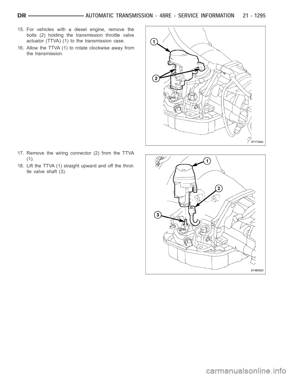
15. For vehicles with a diesel engine, remove the
bolts (2) holding the transmission throttle valve
actuator (TTVA) (1) to the transmission case.
16. Allow the TTVA (1) to rotate clockwise away from
the transmission.
17. Remove the wiring connector (2) from the TTVA
(1).
18. Lift the TTVA (1) straight upward and off the throt-
tle valve shaft (3).
Page 3837 of 5267
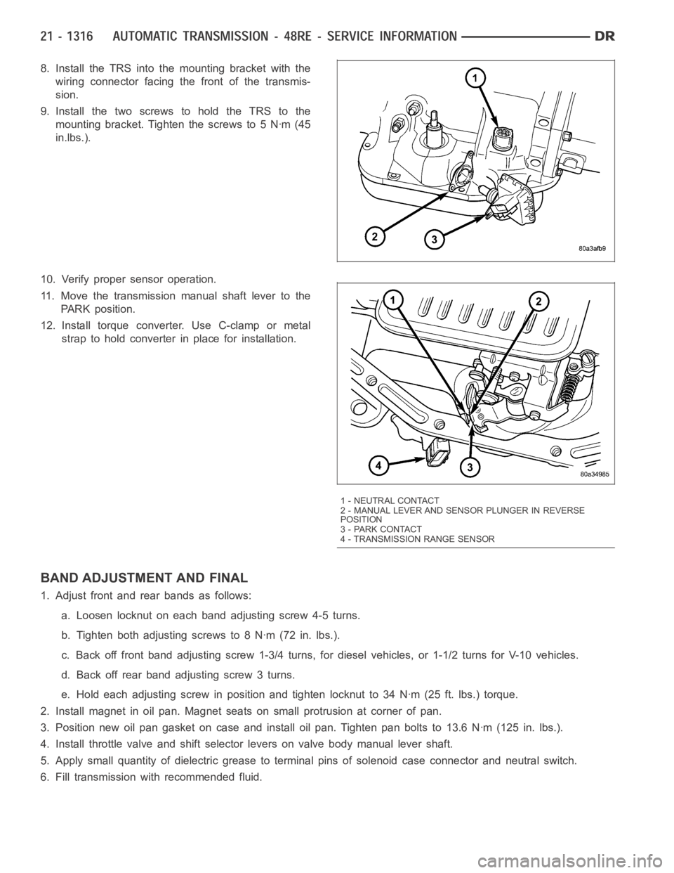
8. Install the TRS into the mounting bracket with the
wiring connector facing the front of the transmis-
sion.
9. Install the two screws to hold the TRS to the
mounting bracket. Tighten the screws to 5 Nꞏm (45
in.lbs.).
10. Verify proper sensor operation.
11. Move the transmission manual shaft lever to the
PARK position.
12. Install torque converter. Use C-clamp or metal
strap to hold converter in place for installation.
BAND ADJUSTMENT AND FINAL
1. Adjust front and rear bands as follows:
a. Loosen locknut on each band adjusting screw 4-5 turns.
b. Tighten both adjusting screws to 8 Nꞏm (72 in. lbs.).
c. Back off front band adjusting screw 1-3/4 turns, for diesel vehicles, or1-1/2 turns for V-10 vehicles.
d. Back off rear band adjusting screw 3 turns.
e. Hold each adjusting screw in position and tighten locknut to 34 Nꞏm (25 ft. lbs.) torque.
2. Install magnet in oil pan. Magnet seats on small protrusion at corner of pan.
3. Position new oil pan gasket on case and install oil pan. Tighten pan boltsto 13.6 Nꞏm (125 in. lbs.).
4. Install throttle valve and shift selector levers on valve body manual lever shaft.
5. Apply small quantity of dielectric grease to terminal pins of solenoid case connector and neutral switch.
6. Fill transmission with recommended fluid.
1 - NEUTRAL CONTACT
2 - MANUAL LEVER AND SENSOR PLUNGER IN REVERSE
POSITION
3 - PARK CONTACT
4 - TRANSMISSION RANGE SENSOR