2006 DODGE RAM SRT-10 wiring
[x] Cancel search: wiringPage 3840 of 5267
17. For vehicles equipped with a diesel engine, posi-
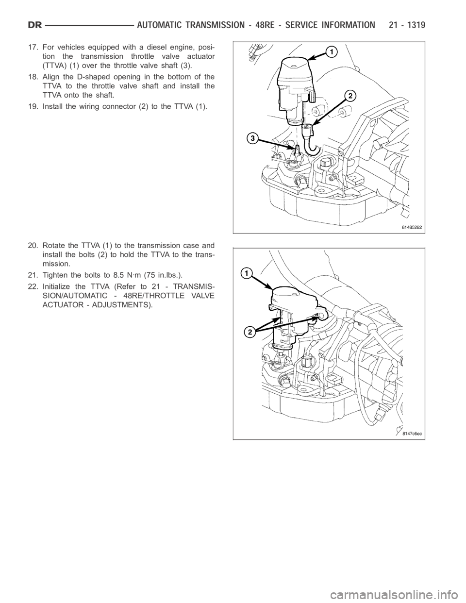
tion the transmission throttle valve actuator
(TTVA) (1) over the throttle valve shaft (3).
18. Align the D-shaped opening in the bottom of the
TTVA to the throttle valve shaft and install the
TTVA onto the shaft.
19. Install the wiring connector (2) to the TTVA (1).
20. Rotate the TTVA (1) to the transmission case and
install the bolts (2) to hold the TTVA to the trans-
mission.
21. Tighten the bolts to 8.5 Nꞏm (75 in.lbs.).
22. Initialize the TTVA (Refer to 21 - TRANSMIS-
SION/AUTOMATIC - 48RE/THROTTLE VALVE
ACTUATOR - ADJUSTMENTS).
Page 3859 of 5267
DESCRIPTION Nꞏm Ft. Lbs. In. Lbs.
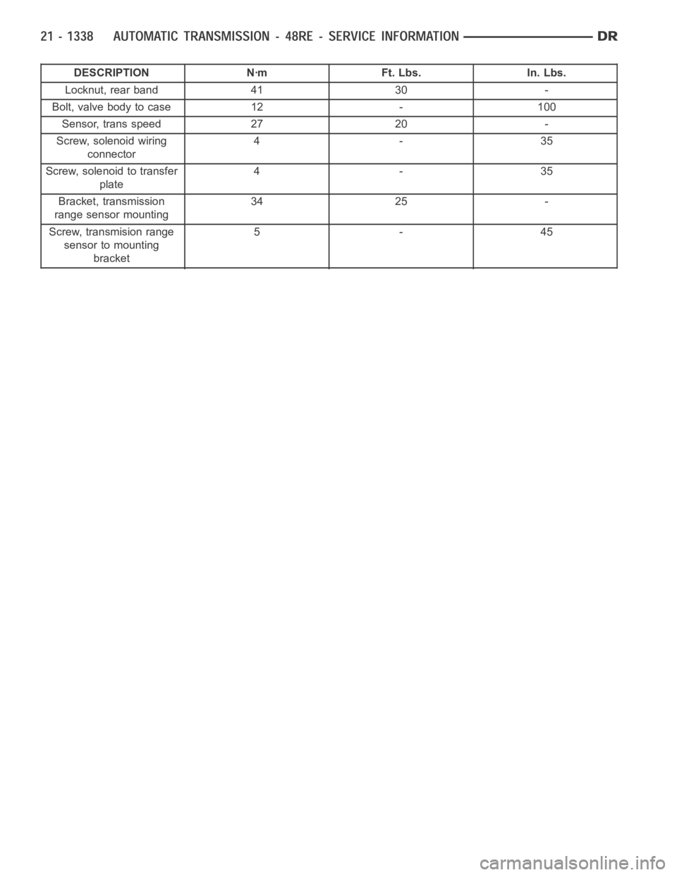
Locknut, rear band 41 30 -
Bolt, valve body to case 12 - 100
Sensor, trans speed 27 20 -
Screw, solenoid wiring
connector4-35
Screw, solenoid to transfer
plate4-35
Bracket, transmission
range sensor mounting34 25 -
Screw, transmision range
sensor to mounting
bracket5-45
Page 3888 of 5267
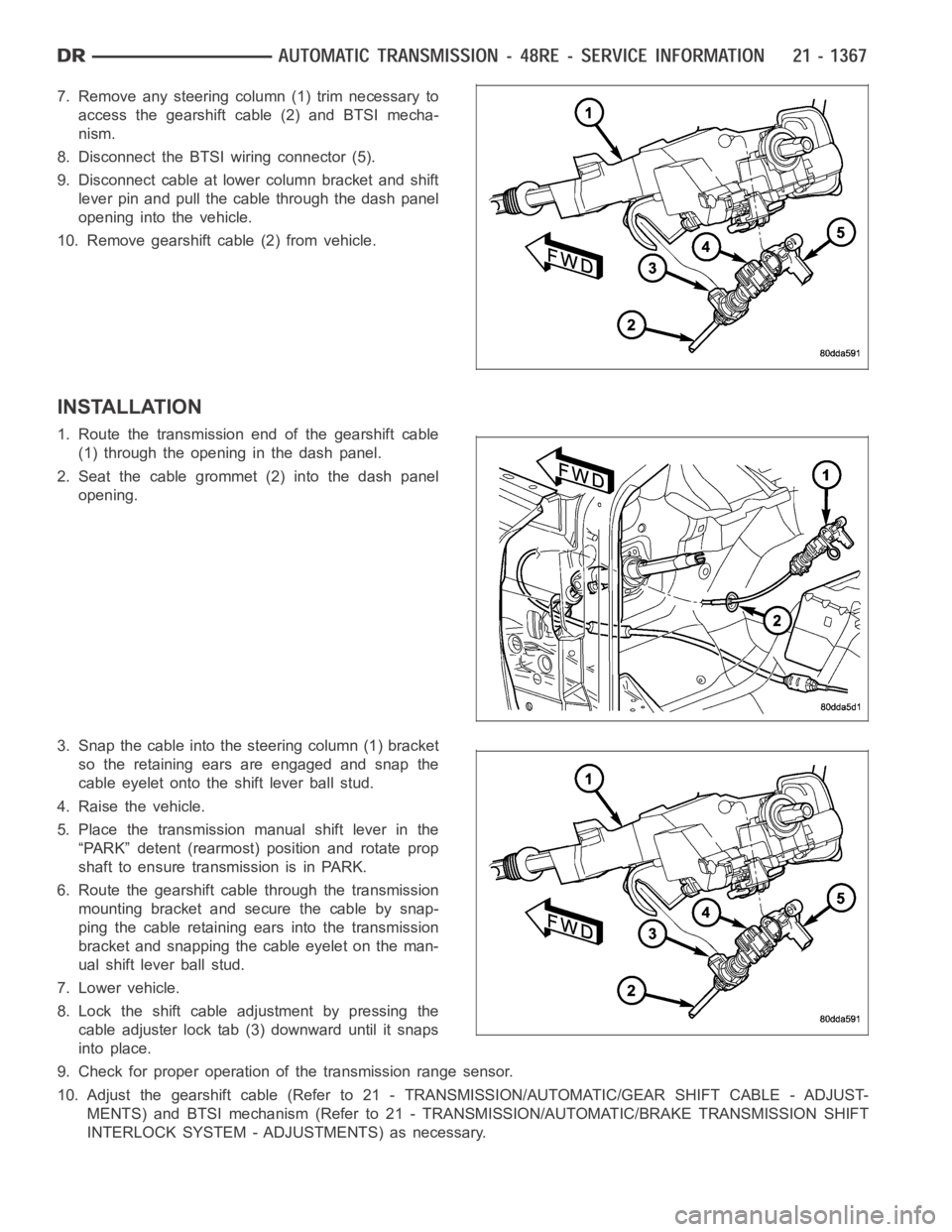
7. Remove any steering column (1) trim necessary to
access the gearshift cable (2) and BTSI mecha-
nism.
8. Disconnect the BTSI wiring connector (5).
9. Disconnect cable at lower column bracket and shift
lever pin and pull the cable through the dash panel
opening into the vehicle.
10. Remove gearshift cable (2) from vehicle.
INSTALLATION
1. Route the transmission end of the gearshift cable
(1) through the opening in the dash panel.
2. Seat the cable grommet (2) into the dash panel
opening.
3. Snap the cable into the steering column (1) bracket
so the retaining ears are engaged and snap the
cable eyelet onto the shift lever ball stud.
4. Raise the vehicle.
5. Place the transmission manual shift lever in the
“PARK” detent (rearmost) position and rotate prop
shaft to ensure transmission is in PARK.
6. Route the gearshift cable through the transmission
mounting bracket and secure the cable by snap-
ping the cable retaining ears into the transmission
bracket and snapping the cable eyelet on the man-
ual shift lever ball stud.
7. Lower vehicle.
8. Lock the shift cable adjustment by pressing the
cable adjuster lock tab (3) downward until it snaps
into place.
9. Check for proper operation of the transmission range sensor.
10. Adjust the gearshift cable (Refer to 21 - TRANSMISSION/AUTOMATIC/GEAR SHIFT CABLE - ADJUST-
MENTS) and BTSI mechanism (Refer to 21 - TRANSMISSION/AUTOMATIC/BRAKE TRANSMISSION SHIFT
INTERLOCK SYSTEM - ADJUSTMENTS) as necessary.
Page 3921 of 5267
d. Push overdrive piston into position in retainer.
e. Verify that the locating lugs entered the lug bores in the retainer.
6. Install intermediate shaft spacer on intermediate shaft.
7. Install overdrive piston thrust plate on overdrive piston.
8. Install overdrive piston thrust bearing on overdrive piston.
9. Install transmission speed sensorand o-ring seal in overdrive case.
INSTALLATION
1. Be sure overdrive unit Alignment Tool 6227-2 is
fully seated before moving unit. If tool is not seated
and gear splines rotate out of alignment, overdrive
unit will have to be disassembled in order to realign
splines.
2. If overdrive piston retainer was not removed during
service and original case gasket is no longer reus-
able, prepare new gasket by trimming it.
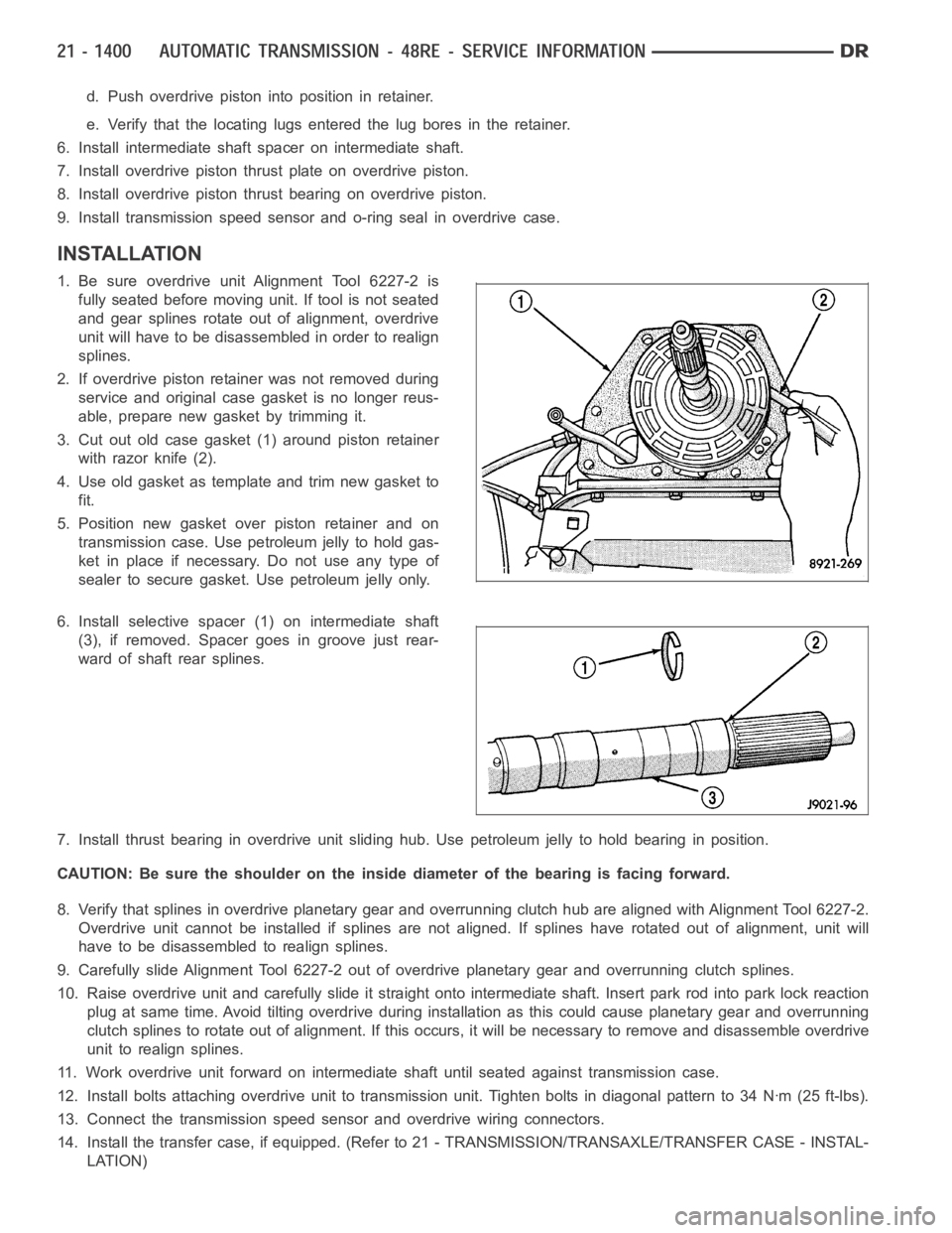
3. Cut out old case gasket (1) around piston retainer
with razor knife (2).
4. Use old gasket as template and trim new gasket to
fit.
5. Position new gasket over piston retainer and on
transmission case. Use petroleum jelly to hold gas-
ket in place if necessary. Do not use any type of
sealer to secure gasket. Use petroleum jelly only.
6. Install selective spacer (1) on intermediate shaft
(3), if removed. Spacer goes in groove just rear-
ward of shaft rear splines.
7. Install thrust bearing in overdrive unit sliding hub. Use petroleum jelly to hold bearing in position.
CAUTION: Be sure the shoulder on the inside diameter of the bearing is facingforward.
8. Verify that splines in overdrive planetary gear and overrunning clutchhub are aligned with Alignment Tool 6227-2.
Overdrive unit cannot be installed if splines are not aligned. If splines have rotated out of alignment, unit will
have to be disassembled to realign splines.
9. Carefully slide Alignment Tool 6227-2 out of overdrive planetary gear and overrunning clutch splines.
10. Raise overdrive unit and carefully slide it straight onto intermediate shaft. Insert park rod into park lock reaction
plug at same time. Avoid tilting overdrive during installation as this could cause planetary gear and overrunning
clutch splines to rotate out of alignment. If this occurs, it will be necessary to remove and disassemble overdrive
unit to realign splines.
11. Work overdrive unit forward on intermediate shaft until seated against transmission case.
12. Install bolts attaching overdrive unit to transmission unit. Tightenbolts in diagonal pattern to 34 Nꞏm (25 ft-lbs).
13. Connect the transmission speed sensor and overdrive wiring connectors.
14. Install the transfer case, if equipped. (Refer to 21 - TRANSMISSION/TRANSAXLE/TRANSFER CASE - INSTAL-
LATION)
Page 3946 of 5267
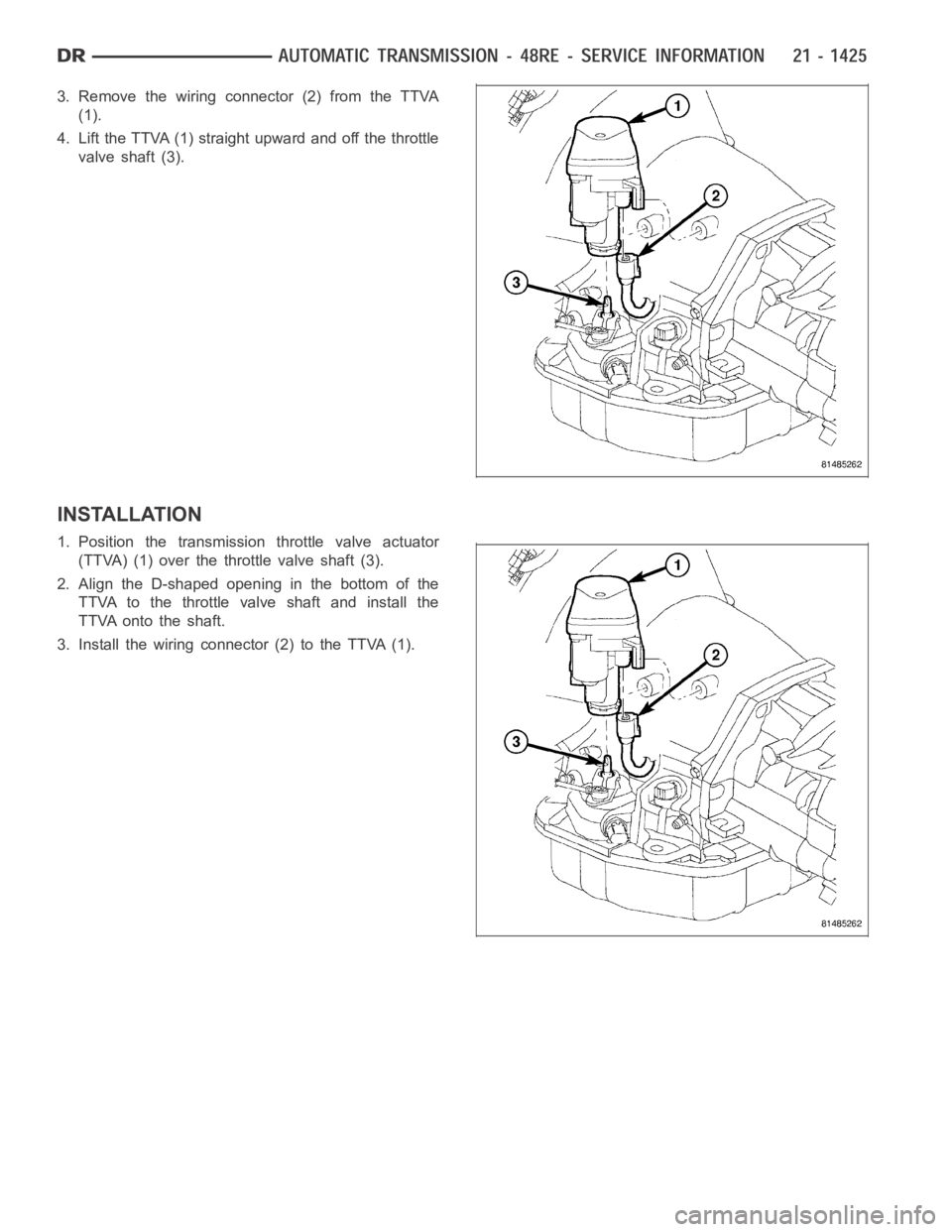
3. Remove the wiring connector (2) from the TTVA
(1).
4. Lift the TTVA (1) straight upward and off the throttle
valve shaft (3).
INSTALLATION
1. Position the transmission throttle valve actuator
(TTVA) (1) over the throttle valve shaft (3).
2. Align the D-shaped opening in the bottom of the
TTVA to the throttle valve shaft and install the
TTVA onto the shaft.
3. Install the wiring connector (2) to the TTVA (1).
Page 3961 of 5267
SWITCH-TOW/HAUL OVERDRIVE
DESCRIPTION
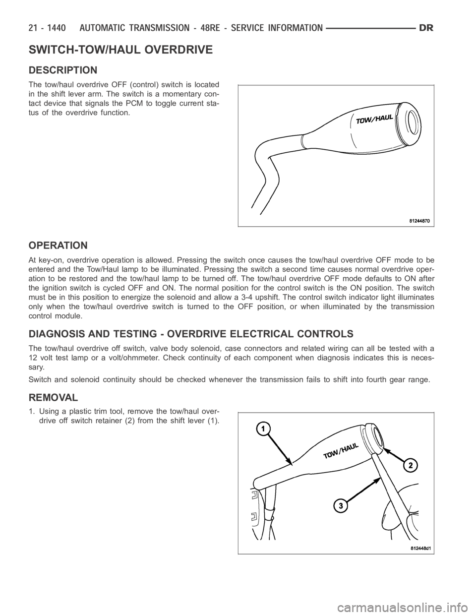
The tow/haul overdrive OFF (control) switch is located
in the shift lever arm. The switch is a momentary con-
tact device that signals the PCM to toggle current sta-
tus of the overdrive function.
OPERATION
At key-on, overdrive operation is allowed. Pressing the switch once causes the tow/haul overdrive OFF mode to be
entered and the Tow/Haul lamp to be illuminated. Pressing the switch a second time causes normal overdrive oper-
ationtoberestoredandthetow/haullamptobeturnedoff.Thetow/hauloverdrive OFF mode defaults to ON after
the ignition switch is cycled OFF and ON. The normal position for the control switch is the ON position. The switch
must be in this position to energize the solenoid and allow a 3-4 upshift. The control switch indicator light illuminates
only when the tow/haul overdrive switch is turned to the OFF position, or when illuminated by the transmission
control module.
DIAGNOSIS AND TESTING - OVERDRIVE ELECTRICAL CONTROLS
The tow/haul overdrive off switch, valve body solenoid, case connectors and related wiring can all be tested with a
12 volt test lamp or a volt/ohmmeter. Check continuity of each component when diagnosis indicates this is neces-
sary.
Switch and solenoid continuity shouldbe checked whenever the transmission fails to shift into fourth gear range.
REMOVAL
1. Using a plastic trim tool, remove the tow/haul over-
drive off switch retainer (2) from the shift lever (1).
Page 3964 of 5267
is also sent by the cluster. In REVERSE range a second contact set closes thecircuit providing power to the
reverse lamps.
Indicated Gear Position Transmission
StatusColumn Shifter
Position
Mechanical State Electronic Display
(Ignition Unlocked)Electronic Display
(Ignition On)
P P P Vehicle is in PARK
with the pawl
engaged.In the PARK gate.
R The PARK pawl is
disengaged and the
vehicle is free to
roll, but REVERSE
is not engaged.Between the PARK
and REVERSE
gates.
R R R The transmission is
hydraulically in
REVERSE.In the REVERSE
gate.
N The transmission is
transitioning
between REVERSE
and NEUTRAL.Between the
REVERSE and
NEUTRAL gates.
N N N The vehicle is in
NEUTRAL.In the NEUTRAL
gate.
N The transmission is
transitioning
between NEUTRAL
and DRIVE, but is
not in DRIVE.Between the
NEUTRAL and
DRIVE gates.
D D D The transmission is
hydraulically in
DRIVE.In the DRIVE gate,
2 2 2 The transmission is
hydraulically in
Manual SECOND.In the SECOND
gate.
1 1 1 The transmission is
hydraulically in
Manual FIRST.In the FIRST gate.
DIAGNOSIS AND TESTING - TRANSMISSION RANGE SENSOR (TRS)
NOTE: For all circuit identification in the following steps, Refer to the appropriate Wiring Information.
1. Raise vehicle on suitable hoist.
2. Disconnect the vehicle’s shift cable from the manual lever.
3. With the manual lever in the PARK position (the PARK position is with the manual lever moved to the full rear-
ward position), measure the resistance between the Park/Neutral PositionSensepinoftheTRSandthetrans-
mission case. The resistance should be less than 5 ohms.
4. With the manual lever in the NEUTRAL position (the NEUTRAL position is with the manual lever moved two
detents forward of the full rearward position), measure the resistance between the Park/Neutral Position Sense
pin of the TRS and the transmission case. The resistance should be less than5ohms.
5. If the resistance is greater than 5 ohms in either of the previous steps, check for a dirty contact between the tip
of the TRS rod and the valve body manual lever. If the contact is OK, replace the TRS.
6. With the manual lever in the REVERSE position (the REVERSE position is with the manual lever moved one
detent forward of the full rearward position), measure the resistance between the Fused Ignition Switch Output
Page 3965 of 5267

and the Back-up Lamp feed pins of the TRS. The resistance should be less than5 ohms. If the resistance is
greater than 5 ohms, replace the TRS.
7. With the manual lever in the PARK position (the PARK position is with the manual lever moved to the full rear-
ward position), measure the resistance between the Transmission Range Sensor MUX and the Transmission
Range Sensor 5V Supply pins of the TRS. The resistance should be 522.2 ohms.If the resistance is not correct,
replace the TRS.
8. With the manual lever in the REVERSE position (the REVERSE position is with the manual lever moved one
detent forward of the full rearward position), measure the resistance between the Transmission Range Sensor
MUX and the Transmission Range Sensor 5V Supply pins of the TRS. The resistance should be 206.2 ohms. If
the resistance is not correct, replace the TRS.
9. With the manual lever in the NEUTRAL position (the NEUTRAL position is with the manual lever moved two
detents forward of the full rearward position), measure the resistance between the Transmission Range Sensor
MUX and the Transmission Range Sensor 5V Supply pins of the TRS. The resistance should be 108.6 ohms. If
the resistance is not correct, replace the TRS.
10. With the manual lever in the DRIVE position (the DRIVE position is with the manual lever moved three detents
forward of the full rearward position), measure the resistance between the Transmission Range Sensor MUX
and the Transmission Range Sensor 5V Supply pins of the TRS. The resistanceshould be 59.9 ohms. If the
resistance is not correct, replace the TRS.
11. With the manual lever in the SECOND position (the SECOND position is with the manual lever moved one
detent rearward of the full forward position), measure the resistance between the Transmission Range Sensor
MUX and the Back-up Lamp feed pins of the TRS. The resistance should be 31.9 ohms. If the resistance is not
correct, replace the TRS.
12. With the manual lever in the LOW position (the LOW position is with the manual lever moved to the full forward
position), measure the resistance between the Transmission Range SensorMUX and the Back-up Lamp feed
pins of the TRS. The resistance should be 13.7 ohms. If the resistance is notcorrect, replace the TRS.
REMOVAL
1. Raise vehicle and position drain pan under the
transmission range sensor (TRS).
2. Move the transmission manual lever to the manual
LOW position. The manual LOW position is with
the manual lever in the forward-most detent.
3. Disengage the wiring connector from the TRS.
4. Remove the two screws holding the TRS to the
TRS mounting bracket.
5. Remove the TRS (3) from the TRS mounting
bracket by pulling it straight out of the bracket.