Page 2420 of 5267

IGNITION SWITCH
DESCRIPTION
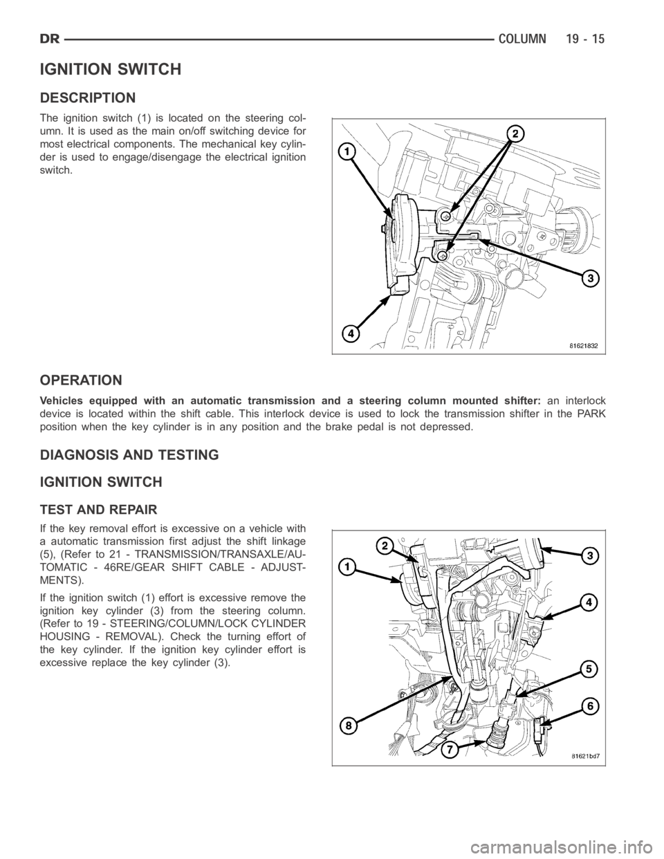
The ignition switch (1) is located on the steering col-
umn. It is used as the main on/off switching device for
most electrical components. The mechanical key cylin-
der is used to engage/disengage the electrical ignition
switch.
OPERATION
Vehicles equipped with an automatic transmission and a steering column mounted shifter:an interlock
device is located within the shift cable. This interlock device is used to lock the transmission shifter in the PARK
position when the key cylinder is in any position and the brake pedal is not depressed.
DIAGNOSIS AND TESTING
IGNITION SWITCH
TEST AND REPAIR
If the key removal effort is excessive on a vehicle with
a automatic transmission first adjust the shift linkage
(5), (Refer to 21 - TRANSMISSION/TRANSAXLE/AU-
TOMATIC - 46RE/GEAR SHIFT CABLE - ADJUST-
MENTS).
If the ignition switch (1) effort is excessive remove the
ignition key cylinder (3) from the steering column.
(Refer to 19 - STEERING/COLUMN/LOCK CYLINDER
HOUSING - REMOVAL). Check the turning effort of
the key cylinder. If the ignition key cylinder effort is
excessive replace the key cylinder (3).
Page 2421 of 5267

REMOVAL
SERVICE PRECAUTIONS
NOTE: The steering column on vehicles equipped with an automatic transmission is not equipped with an
internal locking shaft with the ignition cylinder. Alternative methods of locking the steering wheel for ser-
vice will have to be used.
To service the steering wheel, switches or airbag, Refer to Electrical Restraints and follow all WARNINGS and CAU-
TIONS.
WARNING: The airbag system is a sensitive, complex electro-mechanical unit. Before attempting to diag-
nose, remove or install the airbag system components you must first disconnect and isolate the battery
negative (ground) cable. Then wait two minutes for the system capacitor todischarge. Failure to do so
could result in accidental deployment of the airbag and possible personalinjury. The fasteners, screws, and
bolts, originally used for the airbag components, have special coatings and are specifically designed for the
airbag system. They must never be replaced with any substitutes. Anytime anew fastener is needed,
replace with the correct fasteners provided in the service package or fasteners listed in the parts books.
CAUTION: Do not hammer on steering column shaft. This may cause damage to the shaft or bearing.
CAUTION: Do not attempt to remove the pivot bolts to disassemble the tilting mechanism.
The ignition key must be in the key cylinder for cylinder removal. The key cylinder must be removed first before
removing ignition switch.
1. Remove the negative (ground) cable from the battery.
2. Disable the airbag, (Refer to 8 - ELECTRICAL/RESTRAINTS/DRIVER AIRBAG- REMOVAL).
3. Remove the kneeblocker and steering column reinforcement panel.
4. Remove the lower and upper shrouds.
5. Remove key cylinder. (Refer to 19 - STEERING/COLUMN/LOCK CYLINDER HOUSING - REMOVAL).
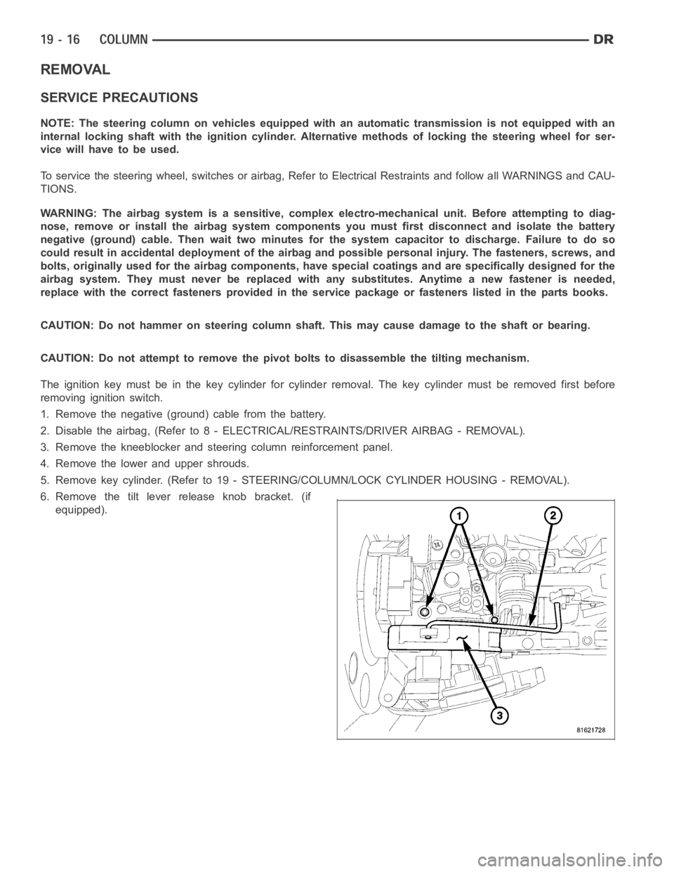
6. Remove the tilt lever release knob bracket. (if
equipped).
Page 2422 of 5267
7. Disconnect the electrical connector at rear of igni-
tion switch (4).
8. Remove ignition switch mounting screws (2).
9. Using a small screwdriver, push on locking tab (3)
and remove switch (1) from steering column.
INSTALLATION
The ignition key must be in the key cylinder for cylinder installation. Thekey cylinder must be removed first before
installing ignition switch.
1. Before installing ignitionswitch (1), rotate the slot
in the switch to the ON position.
2. Position switch (1) to column and install the mount-
ing screws (2). Tighten screw to 3 Nꞏm (26 in. lbs.).
3. Connect the electrical connector to rear of the igni-
tion switch (4). Make sure that locking tabs are fully
seated into wiring connector.
Page 2424 of 5267
IGNITION SWITCH - SRT10
REMOVAL - SRT10
The ignition switch (1) attaches to the lock cylinder
housing (2) on the end opposite the lock cylinder. For
ignition switch terminal and circuit identification, refer
to the Wiring Diagrams sections.
1. Disconnect negative cable from battery.
2. Place key cylinder in RUN position. Through the
hole in the lower shroud (2), depress lock cylinder
retaining tab and remove key cylinder.
3. Remove upper and lower shrouds (3) from steering
column.
4. Disconnect electrical connectors from ignition
switch (1).
Page 2425 of 5267
5. Remove the 2 screws on the top of the multi-func-
tion switch and relocate.
6. Remove ignition switch mounting screw with a #10
To r x
bit.
7. Pull ignition switch from steering column.
Page 2426 of 5267
INSTALLATION - SRT10
1. Ensure the ignition switch is in the RUN position
and the actuator shaft (2) in the lock housing (1) is
in the RUN position.
2. Carefully install the ignition switch. The switch will
snap over the retaining tabs. Install mounting
screw.
3. Install electrical connectors to ignition switch.
4. Install the multi-function switch and tighten the 2
screws.
5. Install upper and lower shrouds.
6. Install key cylinder (cylinder retaining tab will depress only in the RUN position).
7. Connect negative cable to battery.
8. Check for proper operation of ignition switch and key-in warning switch.
Page 2427 of 5267

KEY-IN IGNITION SWITCH
DESCRIPTION
The key-in ignition switch is integral to the ignition switch, which is mounted on the left side of the steering column.
ItclosesapathtogroundfortheCentralTimerModule(CTM)whentheignition key is inserted in the ignition key
cylinder and the driver door ajar switch is closed (driver door is open). The key-in ignition switch opens the ground
path when the key is removed from the ignition key cylinder. The ground pathis also opened when the driver door
ajar switch is open (driver door is closed).
The key-in ignition switch cannot be repaired and, if faulty or damaged, the entire ignition switch must be replaced,
(Refer to 19 - STEERING/COLUMN/IGNITION SWITCH - REMOVAL).
DIAGNOSIS AND TESTING
IGNITION SWITCH AND KEY LOCK CYLINDER
ELECTRICAL DIAGNOSIS
For ignition switch electrical schematics, refer to Ignition Switch in the appropriate section of Electrical Wiring Dia-
grams.
MECHANICAL DIAGNOSIS (KEY DIFFICULT TO ROTATE)
(Refer to 19 - STEERING/COLUMN/IGNITION SWITCH - DIAGNOSIS AND TESTING).
Page 2428 of 5267
KEY CYLINDER
REMOVAL
The ignition key must be in the key cylinder (1) for cyl-
inder removal.
1. Disconnect negative cable from battery.
2. Remove upper and lower covers (shrouds) from
steering column.
3. Place shifter in PARK position.
4. A retaining pin is located at the underside of the
key cylinder assembly.
a. Rotate key to RUN position.
b. Press in on retaining pin while pulling key cyl-
inder (1) from ignition switch.
INSTALLATION
The ignition key must be in the key cylinder (3) for cyl-
inder installation.
1. Install the key cylinder into the housing using care
to align the end of the key cylinder (3) with the igni-
tion switch (1).
2. Push the key cylinder (3) in until it clicks.
3. Replace the upper and lower shrouds.
4. Reconnect the battery.