2006 DODGE RAM SRT-10 ignition
[x] Cancel search: ignitionPage 5044 of 5267
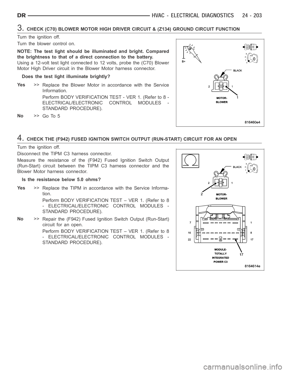
3.CHECK (C70) BLOWER MOTOR HIGH DRIVER CIRCUIT & (Z134) GROUND CIRCUIT FUNCTION
Turn the ignition off.
Turn the blower control on.
NOTE: The test light should be illuminated and bright. Compared
the brightness to that of a direct connection to the battery.
Using a 12-volt test light connected to 12 volts, probe the (C70) Blower
Motor High Driver circuit in the Blower Motor harness connector.
Does the test light illuminate brightly?
Ye s>>
Replace the Blower Motor in accordance with the Service
Information.
Perform BODY VERIFICATION TEST - VER 1. (Refer to 8 -
ELECTRICAL/ELECTRONIC CONTROL MODULES -
STANDARD PROCEDURE).
No>>
Go To 5
4.CHECK THE (F942) FUSED IGNITION SWITCH OUTPUT (RUN-START) CIRCUIT FOR AN OPEN
Turn the ignition off.
Disconnect the TIPM C3 harness connector.
Measure the resistance of the (F942) Fused Ignition Switch Output
(Run-Start) circuit between the TIPM C3 harness connector and the
Blower Motor harness connector.
Is the resistance below 5.0 ohms?
Ye s>>
Replace the TIPM in accordance with the Service Informa-
tion.
Perform BODY VERIFICATION TEST – VER 1. (Refer to 8
- ELECTRICAL/ELECTRONIC CONTROL MODULES -
STANDARD PROCEDURE).
No>>
Repair the (F942) Fused Ignition Switch Output (Run-Start)
circuit for an open.
Perform BODY VERIFICATION TEST – VER 1. (Refer to 8
- ELECTRICAL/ELECTRONIC CONTROL MODULES -
STANDARD PROCEDURE).
Page 5053 of 5267
ACTUATOR DTC DETECTION TEST — DUAL-ZONE
The Actuator DTC Detection Test:
is actuated with a scan tool.
clears all actuator related DTCs when the test is actuated.
supplements the continuous diagnostics on the actuator drive system.
monitors for shorted actuator circuits allowing service to easily diagnose and troubleshoot up to three simul-
taneous shorts. Shorted actuator circuit faults (XXX Control Circuit High or XXX Control Circuit Low) will only
display after running the Actuator DTC Detection Test.
After repairing each DTC, cycle the ignition switch, and then run the Actuator DTC Detection Test again to ensure
that no new DTCs exist. If multiple DTCs are present, beginning with the passenger blend door, diagnose and repair
all short high faults and then short low faults. When the test returns passed, clear all faults and run the Actuator
Calibration function as a final check of system health.
ACTUATOR DTC DETECTION TEST — SINGLE-ZONE
The Actuator DTC Detection Test:
is actuated with a scan tool.
clears all actuator related DTCs when the test is actuated.
supplements the continuous diagnostics on the actuator drive system.
monitors for shorted actuator circuits allowing service to easily diagnose and troubleshoot up to three simul-
taneous shorts. Shorted actuator circuit faults (XXX Control Circuit High or XXX Control Circuit Low) will only
display after running the Actuator DTC Detection Test.
After repairing each DTC, cycle the ignition switch, and then run the Actuator DTC Detection Test again to ensure
that no new DTCs exist. If multiple DTCs are present, beginning with the common circuit, diagnose and repair all
short high faults and then short low faults. When the test returns passed, clear all faults and run the Actuator Cal-
ibration function as a final check of system health.
A/C PERFORMANCE
The A/C system is designed to provide the passenger compartment with low temperature and low humidity air. The
A/C evaporator, located in the HVAC housing is cooled to temperatures nearthe freezing point. As warm damp air
passes over the fins of the A/C evaporator, the air transfers its heat to therefrigerant in the evaporator coils and the
moisture in the air condenses on the evaporator fins. During periods of high heat and humidity, an A/C system will
be more effective in the Recirculation mode (max-A/C). With the system in the Recirculation mode, only air from the
passenger compartment passes through the A/C evaporator. As the passenger compartment air dehumidifies, the
A/C system performance levels rise.
Humidity has an important bearing on the temperature of the air delivered to the interior of the vehicle. It is impor-
tant to understand the effect that humidity has on the performance of the A/C system. When humidity is high, the
A/C evaporator has to perform a double duty. It must lower the air temperature, and it must lower the temperature
of the moisture in the air that condenses on the evaporator fins. Condensing the moisture in the air transfers heat
energy into the evaporator fins and coils. This reduces the amount of heat the A/C evaporator can absorb from the
air. High humidity greatly reduces the ability of the A/C evaporator to lower the temperature of the air.
However, evaporator capacity used to reduce the amount of moisture in the air is not wasted. Wringing some of the
moisture out of the air entering the vehicle adds to the comfort of the passengers. Although, an owner may expect
too much from their A/C system on humid days. A performance test is the best way to determine whether the sys-
tem is performing up to design standards. This test also provides valuableclues as to the possible cause of trouble
with the A/C system. The ambient air temperature in the location where the vehicle will be tested must be a mini-
mum of 21° C (70° F) for this test.
A/C PERFORMANCE TEST
WARNING: Refer to the applicable warnings and cautions for this system before performing the following
operation (Refer to 24 - HEATING & AIR CONDITIONING/PLUMBING - WARNINGS) and (Refer to 24 - HEAT-
ING & AIR CONDITIONING/PLUMBING - CAUTIONS). Failure to follow the warnings and cautions could result
in possible personal injury or death.
Page 5121 of 5267
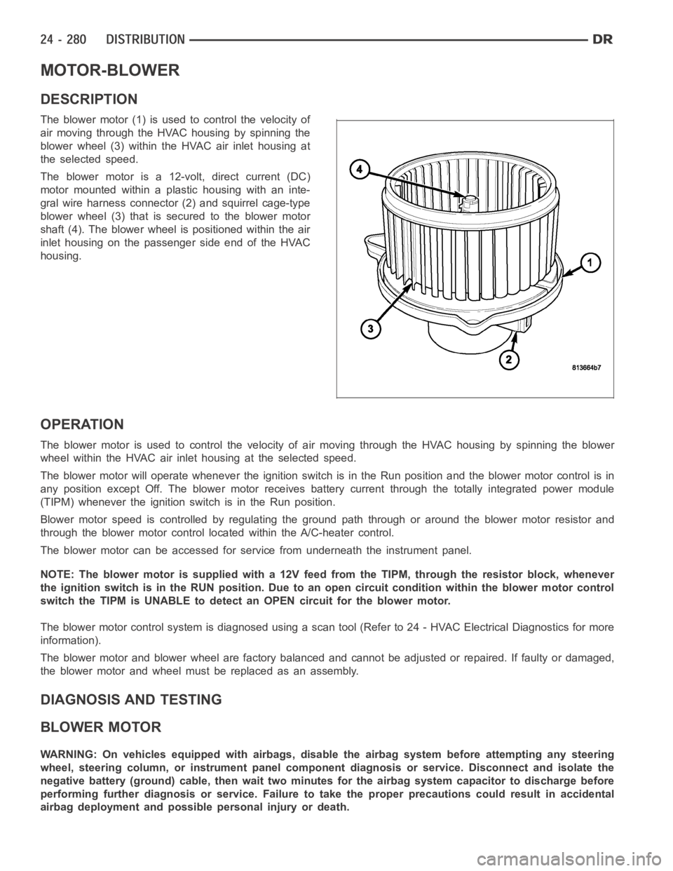
MOTOR-BLOWER
DESCRIPTION
The blower motor (1) is used to control the velocity of
air moving through the HVAC housing by spinning the
blower wheel (3) within the HVAC air inlet housing at
the selected speed.
The blower motor is a 12-volt, direct current (DC)
motormountedwithinaplastichousingwithaninte-
gral wire harness connector (2) and squirrel cage-type
blower wheel (3) that is secured to the blower motor
shaft (4). The blower wheel is positioned within the air
inlet housing on the passenger side end of the HVAC
housing.
OPERATION
The blower motor is used to control the velocity of air moving through the HVAC housing by spinning the blower
wheel within the HVAC air inlet housing at the selected speed.
The blower motor will operate whenever the ignition switch is in the Run position and the blower motor control is in
any position except Off. The blower motor receives battery current through the totally integrated power module
(TIPM) whenever the ignition switch is in the Run position.
Blower motor speed is controlled by regulating the ground path through or around the blower motor resistor and
through the blower motor control located within the A/C-heater control.
The blower motor can be accessed for service from underneath the instrument panel.
NOTE: The blower motor is supplied with a 12V feed from the TIPM, through theresistor block, whenever
the ignition switch is in the RUN position. Due to an open circuit conditionwithin the blower motor control
switch the TIPM is UNABLE to detect an OPEN circuit for the blower motor.
The blower motor control system is diagnosed using a scan tool (Refer to 24 -HVAC Electrical Diagnostics for more
information).
The blower motor and blower wheel are factory balanced and cannot be adjusted or repaired. If faulty or damaged,
the blower motor and wheel must be replaced as an assembly.
DIAGNOSIS AND TESTING
BLOWER MOTOR
WARNING: On vehicles equipped with airbags, disable the airbag system before attempting any steering
wheel, steering column, or instrument panel component diagnosis or service. Disconnect and isolate the
negative battery (ground) cable, then wait two minutes for the airbag system capacitor to discharge before
performing further diagnosis or service. Failure to take the proper precautions could result in accidental
airbag deployment and possible personal injury or death.
Page 5122 of 5267
NOTE: The blower motor is supplied with a 12V feed from the TIPM, through theresistor block, whenever
the ignition switch is in the RUN position. Due to an open circuit conditionwithin the blower motor control
switch the TIPM is UNABLE to detect an OPEN circuit for the blower motor.
To determine if an open condition exists within the blower motor circuit wiring, it is necessary to disconnect the
negative battery cable and check for continuity within the blower motor circuits using an ohmmeter. For circuit
descriptions and diagrams, refer to Air Conditioning/Heater in Group 8W -Wiring Diagrams.
OPERATION
Possible causes of the blower motor not operating include:
Faulty blower motor
Faulty blower motor circuit wiring or wire harness connectors
Faulty blower motor control
Possible causes of the blower motor not operating in one or more speeds include:
Faulty blower motor resistor
Faulty blower motor circuit wiring or wire harness connectors
Faulty blower motor control
VIBRATION
Possible causes of blower motor vibration include:
Improper blower motor mounting
Improper blower wheel mounting
Deformed blower wheel
Out of balance blower wheel due to foreign material in the wheel
Faulty blower motor
NOISE
To determine if the blower motor is the source of the noise, simply switch the blower motor from Off to On. To verify
that the blower motor is the source of the noise, unplug the blower motor wire harness connector and operate the
heating-A/C system. If the noise goes away, possible causes include:
Foreign material in the HVAC air inlet housing
Improper blower motor mounting
Improper blower wheel mounting
Faulty blower motor
Page 5193 of 5267
EMISSIONS CONTROL
DESCRIPTION
STATE DISPLAY TEST MODE
The switch inputs to the Powertrain Control Module (PCM) have two recognized states; HIGH and LOW. For this
reason, the PCM cannot recognize the difference between a selected switchposition versus an open circuit, a short
circuit, or a defective switch. If the State Display screen shows the changefromHIGHtoLOWorLOWtoHIGH,
assume the entire switch circuit to the PCM functions properly. Connect the DRB scan tool to the data link con-
nector and access the state display screen. Then access either State Display Inputs and Outputs or State Display
Sensors.
CIRCUIT ACTUATION TEST MODE
The Circuit Actuation Test Mode checks for proper operation of output circuits or devices the Powertrain Control
Module (PCM) may not internally recognize. The PCM attempts to activate these outputs and allow an observer to
verify proper operation. Most of the tests provide an audible or visual indication of device operation (click of relay
contacts, fuel spray, etc.). Except for intermittent conditions, if a device functions properly during testing, assume the
device, its associated wiring, and driver circuit work correctly. Connect the DRB scan tool to the data link connector
and access the Actuators screen.
DIAGNOSTIC TROUBLE CODES
A Diagnostic Trouble Code (DTC) indicates the PCM has recognized an abnormal condition in the system.
Remember that DTC’s are the results of a system or circuit failure, but do not directly identify the failed
component or components.
BULB CHECK
Each time the ignition key is turned to the ON position, the malfunction indicator (check engine) lamp on the instru-
ment panel should illuminate for approximately 2 seconds then go out. Thisis done for a bulb check.
OBTAINING DTC’S USING DRB SCAN TOOL
1. Obtain the applicable Powertrain Diagnostic Manual.
2. Obtain the DRB Scan Tool.
3. Connect the DRB Scan Tool to the data link (diagnostic) connector. This connector is located in the passenger
compartment at the lower edge of instrument panel, and near the steering column.
4. Turn the ignition switch on and access the “Read Fault” screen.
5. Record all the DTC’s and “freeze frame” information shown on the DRB scantool.
6. To erase DTC’s, use the “Erase Trouble Code” data screen on the DRB scan tool.Do not erase any DTC’s
until problems have been investigated and repairs have been performed.
TA S K M A N A G E R
The PCM is responsible for efficiently coordinating the operation of all the emissions-related components. The PCM
is also responsible for determining if the diagnostic systems are operating properly. The software designed to carry
out these responsibilities is called the ’Task Manager’.
MONITORED SYSTEMS
There are new electronic circuit monitors that check fuel, emission, engine and ignition performance. These moni-
tors use information from various sensor circuits to indicate the overalloperation of the fuel, engine, ignition and
emission systems and thus the emissions performance of the vehicle.
The fuel, engine, ignition and emission systems monitors do not indicate aspecific component problem. They do
indicate that there is an implied problem within one of the systems and thata specific problem must be diagnosed.
If any of these monitors detect a problem affecting vehicle emissions, theMalfunction Indicator Lamp (MIL) will be
illuminated. These monitors generate Diagnostic Trouble Codes that can be displayed with the MIL or a scan tool.
Page 5197 of 5267
COMPONENT MONITORS
There are several components that will affect vehicle emissions if they malfunction. If one of these components
malfunctions the Malfunction Indicator Lamp (MIL) will illuminate.
Some of the component monitors are checking for proper operation of the part. Electrically operated components
now have input (rationality) and output (functionality) checks. Previously, a component like the Throttle Position sen-
sor (TPS) was checked by the PCM for an open or shorted circuit. If one of these conditions occurred, a DTC was
set. Now there is a check to ensure that the component is working. This is donebywatchingforaTPSindication
of a greater or lesser throttle opening than MAP and engine rpm indicate. Inthe case of the TPS, if engine vacuum
is high and engine rpm is 1600 or greater, and the TPS indicates a large throttle opening, a DTC will be set. The
same applies to low vacuum if the TPS indicates a small throttle opening.
All open/short circuit checks, or any component that has an associated limp-in, will set a fault after 1 trip with the
malfunction present. Components without an associated limp-in will taketwo trips to illuminate the MIL.
OPERATION
OPERATION
The Powertrain Control Module (PCM) monitors many
different circuits in the fuel injection, ignition, emission
and engine systems. If the PCM senses a problem
withamonitoredcircuitoftenenoughtoindicatean
actual problem, it stores a Diagnostic Trouble Code
(DTC) in the PCM’s memory. If the problem is repaired
or ceases to exist, the PCM cancels the code after 40
warm-up cycles. Diagnostic trouble codes that affect
vehicle emissions illuminatethe Malfunction Indicator
Lamp (MIL). The MIL is displayed as an engine icon
(graphic) on the instrument panel. Refer to Malfunction
Indicator Lamp in this section.
Certain criteria must be met before the PCM stores a
DTC in memory. The criteria may be a specific range
of engine RPM, engine temperature, and/or input volt-
age to the PCM.
The PCM might not store a DTC for a monitored cir-
cuit even though a malfunction has occurred. This
may happen because one of the DTC criteria for the
circuit has not been met.For example,assume the diagnostic trouble code criteria requires the PCM to monitor the
circuit only when the engine operates between 750 and 2000 RPM. Suppose thesensor’s output circuit shorts to
ground when engine operates above 2400 RPM (resulting in 0 volt input to thePCM). Because the condition hap-
pens at an engine speed above the maximum threshold (2000 rpm), the PCM willnot store a DTC.
There are several operating conditions for which the PCM monitors and setsDTC’s. Refer to Monitored Systems,
Components, and Non-Monitored Circuits in this section.
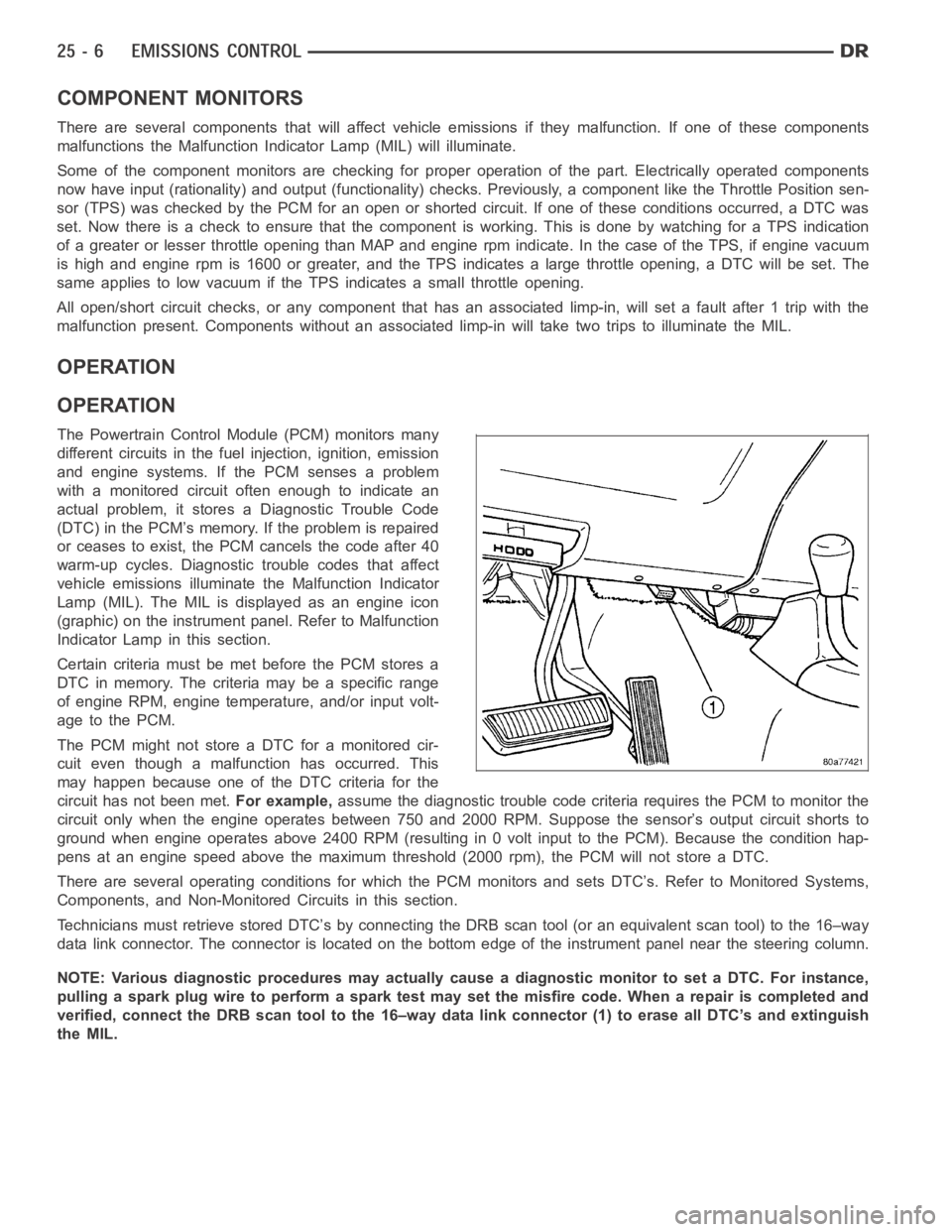
Technicians must retrieve stored DTC’s by connecting the DRB scan tool (oran equivalent scan tool) to the 16–way
data link connector. The connector is located on the bottom edge of the instrument panel near the steering column.
NOTE: Various diagnostic procedures may actually cause a diagnostic monitor to set a DTC. For instance,
pulling a spark plug wire to perform a spark test may set the misfire code. When a repair is completed and
verified, connect the DRB scan tool to the 16–way data link connector (1) toerase all DTC’s and extinguish
the MIL.
Page 5201 of 5267
Engine RPM— A live reading of engine RPM to aid the user in accessing the Similar Conditions Window.
Adaptive Memory Factor— The PCM utilizes both Short Term Compensation and Long Term Adaptive to
calculate the Adaptive Memory Factor for total fuel correction.
Upstream O2S Volts— A live reading of the Oxygen Sensor to indicate its performance. For example, stuck
lean, stuck rich, etc.
SCW Time in Window (Similar Conditions Window Time in Window)—Atimer used by the PCM that
indicates that, after all Similar Conditions have been met, if there has been enough good engine running time
in the SCW without failure detected. This timer is used to increment a Good Trip.
Fuel System Good Trip Counter—ATripCounterusedtoturnOFFtheMILforFuelSystemDTCs.To
increment a Fuel System Good Trip, the engine must be in the Similar Conditions Window, Adaptive Memory
Factor must be less than calibrated threshold and the Adaptive Memory Factor must stay below that threshold
for a calibrated amount of time.
Test Done This Trip— Indicates that the monitor has already been run and completed during the current trip.
MISFIRE
Same Misfire Warm-Up State— Indicates if the misfire occurred when the engine was warmed up above
160° F (71.1°C).
In Similar Misfire Window— An indicator that ’Absolute MAP When Misfire Occurred’ and ’RPM When Mis-
fire Occurred’ are all in the same range when the failure occurred. Indicated by switching from ’NO’ to ’YES’.
Absolute MAP When Misfire Occurred— The stored MAP reading at the time of failure. Informs the user at
what engine load the failure occurred.
Absolute MAP— A live reading of engine load to aid the user in accessing the Similar Conditions Window.
RPM When Misfire Occurred— The stored RPM reading at the time of failure. Informs the user at what
engine RPM the failure occurred.
Engine RPM— A live reading of engine RPM to aid the user in accessing the Similar Conditions Window.
Adaptive Memory Factor— The PCM utilizes both Short Term Compensation and Long Term Adaptive to
calculate the Adaptive Memory Factor for total fuel correction.
200 Rev Counter— Counts 0–100 720 degree cycles.
SCW Cat 200 Rev Counter— Counts when in similar conditions.
SCW FTP 1000 Rev Counter— Counts 0–4 when in similar conditions.
Misfire Good Trip Counter— Counts up to three to turn OFF the MIL.
Misfire Data— Data collected during test.
Test Done This Trip— Indicates YES when the test is done.
NON-MONITORED CIRCUITS
The PCM does not monitor the following circuits, systems and conditions that could have malfunctions causing
driveability problems. The PCM might not store diagnostic trouble codes for these conditions. However, problems
with these systems may cause the PCM to store diagnostic trouble codes for other systems or components.EXAM-
PLE:a fuel pressure problem will not register a fault directly, but could causea rich/lean condition or misfire. This
could cause the PCM to store an oxygen sensor or misfire diagnostic troublecode
FUEL PRESSURE
The fuel pressure regulator controls fuel system pressure. The PCM cannotdetect a clogged fuel pump inlet filter,
clogged in-line fuel filter, or a pinched fuel supply or return line. However, these could result in a rich or lean con-
dition causing the PCM to store an oxygen sensor or fuel system diagnostic trouble code.
SECONDARY IGNITION CIRCUIT
The PCM cannot detect an inoperative ignition coil, fouled or worn spark plugs, ignition cross firing, or open spark
plug cables.
CYLINDER COMPRESSION
The PCM cannot detect uneven, low, or high engine cylinder compression.