2006 DODGE RAM SRT-10 ignition
[x] Cancel search: ignitionPage 2437 of 5267
UPPER STEERING COUPLING
REMOVAL
1. Disconnect the negative battery cable.
NOTE: The steering column on vehicles with an automatic transmission may not be equipped with an inter-
nal locking shaft that allows the ignition key cylinder to be locked with the key. Alternative methods of lock-
ing the steering wheel for service will have to be used.
2. Lock the steering wheel with the tire in the straight position.
3. Remove and discard the lower pinch bolt.
4. Lower the steering coupler shaft from the column.
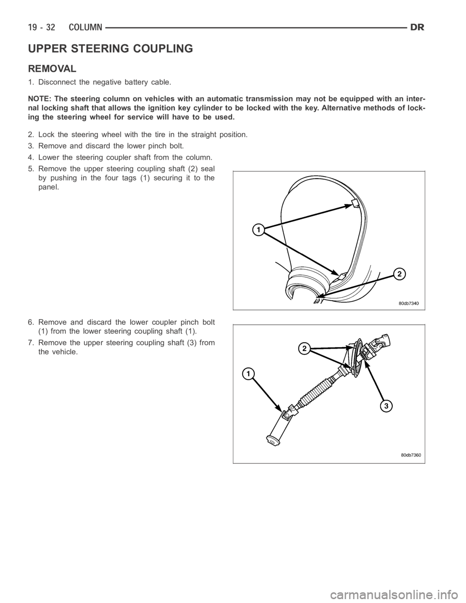
5. Remove the upper steering coupling shaft (2) seal
by pushing in the four tags (1) securing it to the
panel.
6. Remove and discard the lower coupler pinch bolt
(1) from the lower steering coupling shaft (1).
7. Remove the upper steering coupling shaft (3) from
the vehicle.
Page 2439 of 5267
LOWER STEERING COUPLING
REMOVAL
ALLLD&HDEXCEPT4X4HD
1. Disconnect the negative battery cable.
2. Raise and support the vehicle.
NOTE: The steering column on vehicles with an automatic transmission may not be equipped with an inter-
nal locking shaft that allows the ignition key cylinder to be locked with the key. Alternative methods of lock-
ing the steering wheel for service will have to be used.
3. Lock the steering wheel with the tire in the straight position.
4. Remove the left front tire and wheel assembly.
5. Mark both coupler connections for proper installation.
6. Remove and discard the upper coupler pinch bolt.
7. Remove and discard the lower coupler pinch bolt.
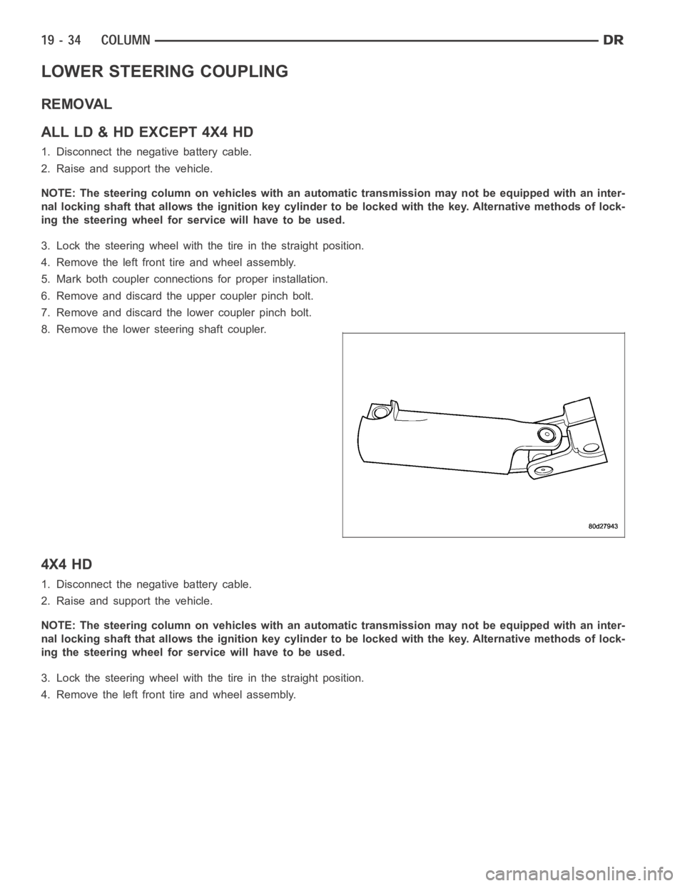
8. Remove the lower steering shaft coupler.
4X4 HD
1. Disconnect the negative battery cable.
2. Raise and support the vehicle.
NOTE: The steering column on vehicles with an automatic transmission may not be equipped with an inter-
nal locking shaft that allows the ignition key cylinder to be locked with the key. Alternative methods of lock-
ing the steering wheel for service will have to be used.
3. Lock the steering wheel with the tire in the straight position.
4. Remove the left front tire and wheel assembly.
Page 2444 of 5267
GEAR - INDEPENDENT FRONT SUSPENSION
DESCRIPTION
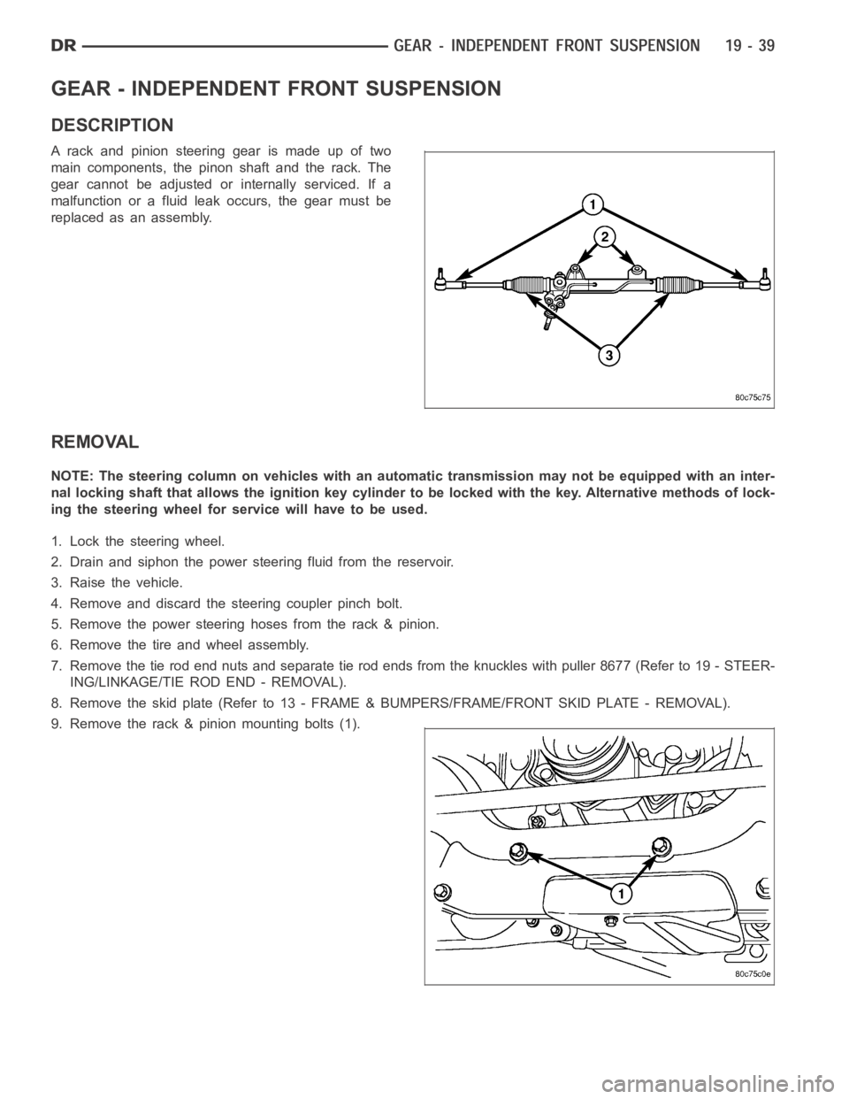
A rack and pinion steering gear is made up of two
main components, the pinon shaft and the rack. The
gear cannot be adjusted or internally serviced. If a
malfunction or a fluid leak occurs, the gear must be
replaced as an assembly.
REMOVAL
NOTE: The steering column on vehicles with an automatic transmission may not be equipped with an inter-
nal locking shaft that allows the ignition key cylinder to be locked with the key. Alternative methods of lock-
ing the steering wheel for service will have to be used.
1. Lock the steering wheel.
2. Drain and siphon the power steering fluid from the reservoir.
3. Raise the vehicle.
4. Remove and discard the steering coupler pinch bolt.
5. Remove the power steering hoses from the rack & pinion.
6. Remove the tire and wheel assembly.
7. Remove the tie rod end nuts and separate tie rod ends from the knuckles withpuller8677(Referto19-STEER-
ING/LINKAGE/TIE ROD END - REMOVAL).
8. Remove the skid plate (Refer to 13 - FRAME & BUMPERS/FRAME/FRONT SKID PLATE - REMOVAL).
9. Remove the rack & pinion mounting bolts (1).
Page 2449 of 5267
GEAR - LINK/COIL
DESCRIPTION
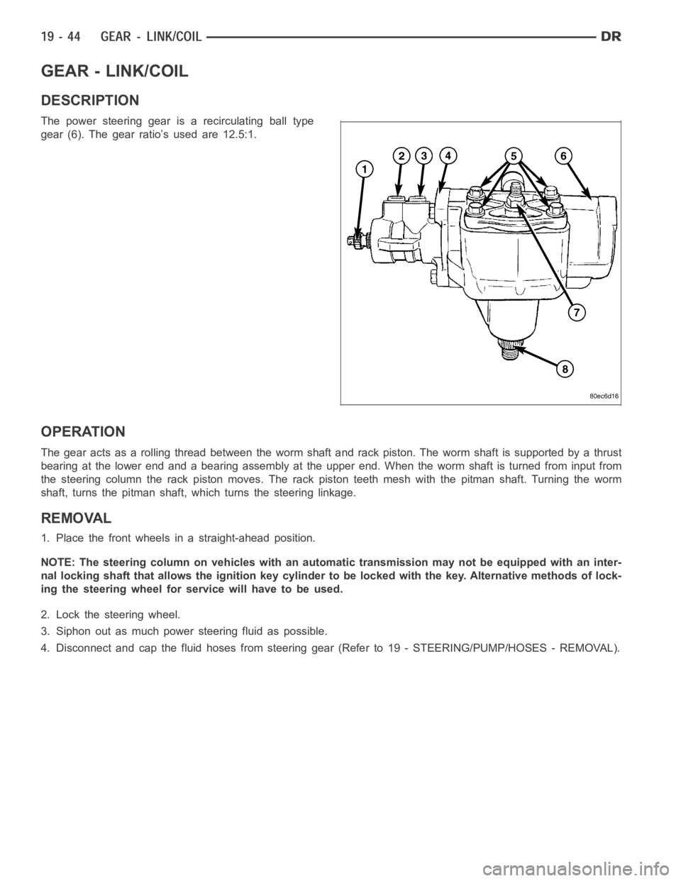
The power steering gear is a recirculating ball type
gear (6). The gear ratio’s used are 12.5:1.
OPERATION
The gear acts as a rolling thread between the worm shaft and rack piston. Theworm shaft is supported by a thrust
bearing at the lower end and a bearing assembly at the upper end. When the worm shaft is turned from input from
the steering column the rack piston moves. The rack piston teeth mesh with the pitman shaft. Turning the worm
shaft, turns the pitman shaft, which turns the steering linkage.
REMOVAL
1. Place the front wheels in a straight-ahead position.
NOTE: The steering column on vehicles with an automatic transmission may not be equipped with an inter-
nal locking shaft that allows the ignition key cylinder to be locked with the key. Alternative methods of lock-
ing the steering wheel for service will have to be used.
2. Lock the steering wheel.
3. Siphon out as much power steering fluid as possible.
4. Disconnect and cap the fluid hoses from steering gear (Refer to 19 - STEERING/PUMP/HOSES - REMOVAL).
Page 2726 of 5267
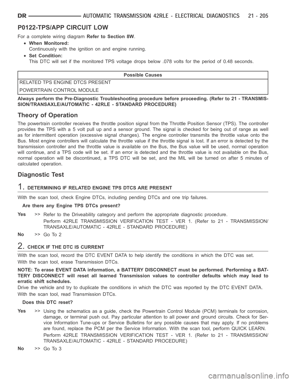
P0122-TPS/APP CIRCUIT LOW
For a complete wiring diagramRefer to Section 8W.
When Monitored:
Continuously with the ignition on and engine running.
Set Condition:
This DTC will set if the monitored TPS voltage drops below .078 volts for theperiod of 0.48 seconds.
Possible Causes
RELATED TPS ENGINE DTCS PRESENT
POWERTRAIN CONTROL MODULE
Always perform the Pre-Diagnostic Troubleshooting procedure before proceeding. (Refer to 21 - TRANSMIS-
SION/TRANSAXLE/AUTOMATIC - 42RLE - STANDARD PROCEDURE)
Theory of Operation
The powertrain controller receives the throttle position signal from theThrottle Position Sensor (TPS). The controller
provides the TPS with a 5 volt pull up and a sensor ground. The signal is checked for being out of range as well
as for intermittent operation (excessive signal changes). The engine controller transmits the throttle value onto the
Bus. Most engine controllers will calculate the throttle value if the throttle signal is lost. If an error is detected by the
transmission controller and the throttle value is available on the Bus, the Bus value will be used, normal operation
will continue, and a TPS code will be set. If an error is detected and the throttle value is not available on the Bus,
normal operation will be discontinued, a TPS DTC will be set, and the MIL will be turned on after 5 minutes of
calculated operation.
Diagnostic Test
1.DETERMINING IF RELATED ENGINE TPS DTCS ARE PRESENT
With the scan tool, check Engine DTCs, including pending DTCs and one trip failures.
Are there any Engine TPS DTCs present?
Ye s>>
Refer to the Driveability category and perform the appropriate diagnostic procedure.
Perform 42RLE TRANSMISSION VERIFICATION TEST - VER 1. (Refer to 21 - TRANSMISSION/
TRANSAXLE/AUTOMATIC - 42RLE - STANDARD PROCEDURE)
No>>
Go To 2
2.CHECK IF THE DTC IS CURRENT
With the scan tool, record the DTC EVENT DATA to help identify the conditionsinwhichtheDTCwasset.
With the scan tool, erase Transmission DTCs.
NOTE: To erase EVENT DATA information, a BATTERY DISCONNECT must be performed. Performing a BAT-
TERY DISCONNECT will reset all learned Transmission values to controllerdefaults which may lead to
erratic shift schedules.
Drive the vehicle and try to duplicate the conditions in which the DTC was reported by the DTC EVENT DATA.
With the scan tool, read Transmission DTCs.
Does this DTC reset?
Ye s>>
Using the schematics as a guide, check the Powertrain Control Module (PCM)terminals for corrosion,
damage, or terminal push out. Pay particular attention to all power and ground circuits. Check for Ser-
vice Information Tune-ups or Service Bulletins for any possible causes that may apply. If no problems
are found, replace the PCM per the Service Information. With the scan tool,perform QUICK LEARN.
Perform 42RLE TRANSMISSION VERIFICATION TEST - VER 1. (Refer to 21 - TRANSMISSION/
TRANSAXLE/AUTOMATIC - 42RLE - STANDARD PROCEDURE)
No>>
Go To 3
Page 2728 of 5267
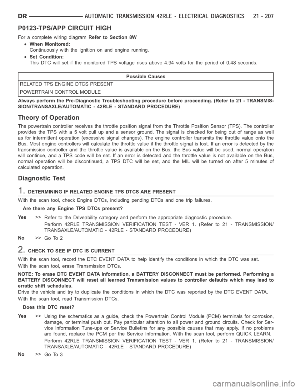
P0123-TPS/APP CIRCUIT HIGH
For a complete wiring diagramRefer to Section 8W
When Monitored:
Continuously with the ignition on and engine running.
Set Condition:
This DTC will set if the monitored TPS voltage rises above 4.94 volts for theperiod of 0.48 seconds.
Possible Causes
RELATED TPS ENGINE DTCS PRESENT
POWERTRAIN CONTROL MODULE
Always perform the Pre-Diagnostic Troubleshooting procedure before proceeding. (Refer to 21 - TRANSMIS-
SION/TRANSAXLE/AUTOMATIC - 42RLE - STANDARD PROCEDURE)
Theory of Operation
The powertrain controller receives the throttle position signal from theThrottle Position Sensor (TPS). The controller
provides the TPS with a 5 volt pull up and a sensor ground. The signal is checked for being out of range as well
as for intermittent operation (excessive signal changes). The engine controller transmits the throttle value onto the
Bus. Most engine controllers will calculate the throttle value if the throttle signal is lost. If an error is detected by the
transmission controller and the throttle value is available on the Bus, the Bus value will be used, normal operation
will continue, and a TPS code will be set. If an error is detected and the throttle value is not available on the Bus,
normal operation will be discontinued, a TPS DTC will be set, and the MIL will be turned on after 5 minutes of
calculated operation.
Diagnostic Test
1.DETERMINING IF RELATED ENGINE TPS DTCS ARE PRESENT
With the scan tool, check Engine DTCs, including pending DTCs and one trip failures.
Are there any Engine TPS DTCs present?
Ye s>>
Refer to the Driveability category and perform the appropriate diagnostic procedure.
Perform 42RLE TRANSMISSION VERIFICATION TEST - VER 1. (Refer to 21 - TRANSMISSION/
TRANSAXLE/AUTOMATIC - 42RLE - STANDARD PROCEDURE)
No>>
Go To 2
2.CHECK TO SEE IF DTC IS CURRENT
With the scan tool, record the DTC EVENT DATA to help identify the conditionsinwhichtheDTCwasset.
With the scan tool, erase Transmission DTCs.
NOTE: To erase DTC EVENT DATA information, a BATTERY DISCONNECT must be performed. Performing a
BATTERY DISCONNECT will reset all learned Transmission values to controller defaults which may lead to
erratic shift schedules.
Drive the vehicle and try to duplicate the conditions in which the DTC was reported by the DTC EVENT DATA.
With the scan tool, read Transmission DTCs.
Does this DTC reset?
Ye s>>
Using the schematics as a guide, check the Powertrain Control Module (PCM)terminals for corrosion,
damage, or terminal push out. Pay particular attention to all power and ground circuits. Check for Ser-
vice Information Tune-ups or Service Bulletins for any possible causes that may apply. If no problems
are found, replace the PCM per the Service Information. With the scan tool,perform QUICK LEARN.
Perform 42RLE TRANSMISSION VERIFICATION TEST - VER 1. (Refer to 21 - TRANSMISSION/
TRANSAXLE/AUTOMATIC - 42RLE - STANDARD PROCEDURE)
No>>
Go To 3
Page 2730 of 5267
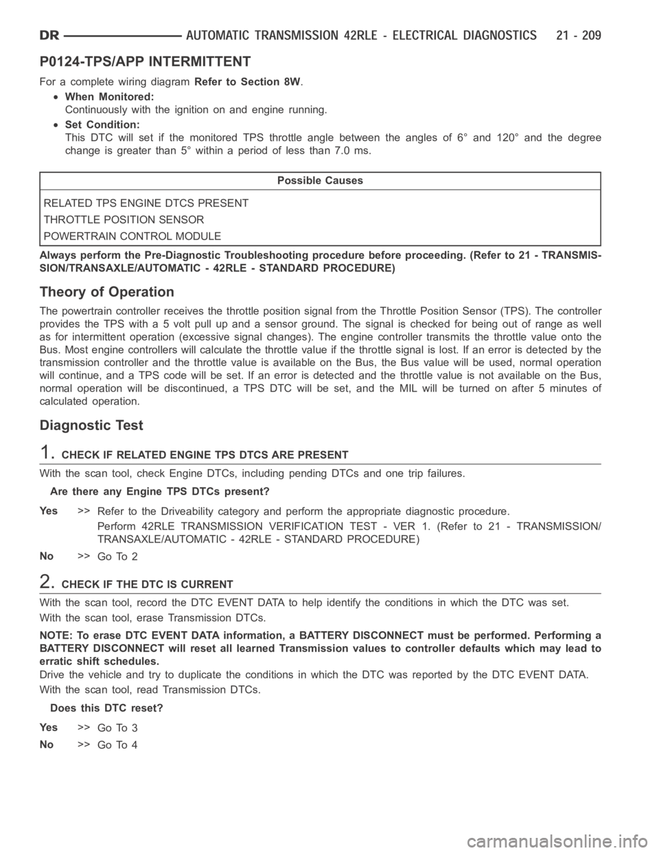
P0124-TPS/APP INTERMITTENT
For a complete wiring diagramRefer to Section 8W.
When Monitored:
Continuously with the ignition on and engine running.
Set Condition:
This DTC will set if the monitored TPS throttle angle between the angles of 6° and 120° and the degree
change is greater than 5° within a period of less than 7.0 ms.
Possible Causes
RELATED TPS ENGINE DTCS PRESENT
THROTTLE POSITION SENSOR
POWERTRAIN CONTROL MODULE
Always perform the Pre-Diagnostic Troubleshooting procedure before proceeding. (Refer to 21 - TRANSMIS-
SION/TRANSAXLE/AUTOMATIC - 42RLE - STANDARD PROCEDURE)
Theory of Operation
The powertrain controller receives the throttle position signal from theThrottle Position Sensor (TPS). The controller
provides the TPS with a 5 volt pull up and a sensor ground. The signal is checked for being out of range as well
as for intermittent operation (excessive signal changes). The engine controller transmits the throttle value onto the
Bus. Most engine controllers will calculate the throttle value if the throttle signal is lost. If an error is detected by the
transmission controller and the throttle value is available on the Bus, the Bus value will be used, normal operation
will continue, and a TPS code will be set. If an error is detected and the throttle value is not available on the Bus,
normal operation will be discontinued, a TPS DTC will be set, and the MIL will be turned on after 5 minutes of
calculated operation.
Diagnostic Test
1.CHECK IF RELATED ENGINE TPS DTCS ARE PRESENT
With the scan tool, check Engine DTCs, including pending DTCs and one trip failures.
Are there any Engine TPS DTCs present?
Ye s>>
Refer to the Driveability category and perform the appropriate diagnostic procedure.
Perform 42RLE TRANSMISSION VERIFICATION TEST - VER 1. (Refer to 21 - TRANSMISSION/
TRANSAXLE/AUTOMATIC - 42RLE - STANDARD PROCEDURE)
No>>
Go To 2
2.CHECK IF THE DTC IS CURRENT
With the scan tool, record the DTC EVENT DATA to help identify the conditionsinwhichtheDTCwasset.
With the scan tool, erase Transmission DTCs.
NOTE: To erase DTC EVENT DATA information, a BATTERY DISCONNECT must be performed. Performing a
BATTERY DISCONNECT will reset all learned Transmission values to controller defaults which may lead to
erratic shift schedules.
Drive the vehicle and try to duplicate the conditions in which the DTC was reported by the DTC EVENT DATA.
With the scan tool, read Transmission DTCs.
Does this DTC reset?
Ye s>>
Go To 3
No>>
Go To 4
Page 2731 of 5267

3.CHECK THE THROTTLE POSITION SENSOR OPERATION
Ignition on, engine not running.
With the scan tool, under Transmission Sensors, monitor the TPS voltage inthe following step.
Slowly open and close the throttle while checking for erratic voltage changes.
Did the TPS voltage change smooth and consistent?
Ye s>>
Using the schematics as a guide, check the Powertrain Control Module (PCM)terminals for corrosion,
damage, or terminal push out. Pay particular attention to all power and ground circuits. Check for Ser-
vice Information Tune-ups or Service Bulletins for any possible causes that may apply. If no problems
are found, replace the PCM per the Service Information. With the scan tool,perform QUICK LEARN.
Perform 42RLE TRANSMISSION VERIFICATION TEST - VER 1. (Refer to 21 - TRANSMISSION/
TRANSAXLE/AUTOMATIC - 42RLE - STANDARD PROCEDURE)
No>>
Replace the Throttle Position Sensor per the Service Information.
Perform 42RLE TRANSMISSION VERIFICATION TEST - VER 1. (Refer to 21 - TRANSMISSION/
TRANSAXLE/AUTOMATIC - 42RLE - STANDARD PROCEDURE)
4.INTERMITTENT WIRING AND CONNECTORS
The conditions necessary to set this DTC are not present at this time.
Using the schematics as a guide, inspect the wiring and connectors specifictothiscircuit.
Wiggle the wires while checking for shorted and open circuits.
Pay particular attention to the TPS signal and sensor ground circuits.
With the scan tool, check the DTC EVENT DATA to help identify the conditionsin which the DTC was set.
Were there any problems found?
Ye s>>
Repair as necessary.
Perform 42RLE TRANSMISSION VERIFICATION TEST - VER 1. (Refer to 21 - TRANSMISSION/
TRANSAXLE/AUTOMATIC - 42RLE - STANDARD PROCEDURE)
No>>
Te s t C o m p l e t e .