2006 DODGE RAM SRT-10 ignition
[x] Cancel search: ignitionPage 2736 of 5267
3.CONDITION P0562 PRESENT
With the scan tool, read Transmission DTCs.
With the scan tool, Check the STARTS SINCE SET counter for P0562.
NOTE: This counter only applies to the last DTC set.
Is the STARTS SINCE SET counter set at 0?
Ye s>>
Go To 4
No>>
Go To 6
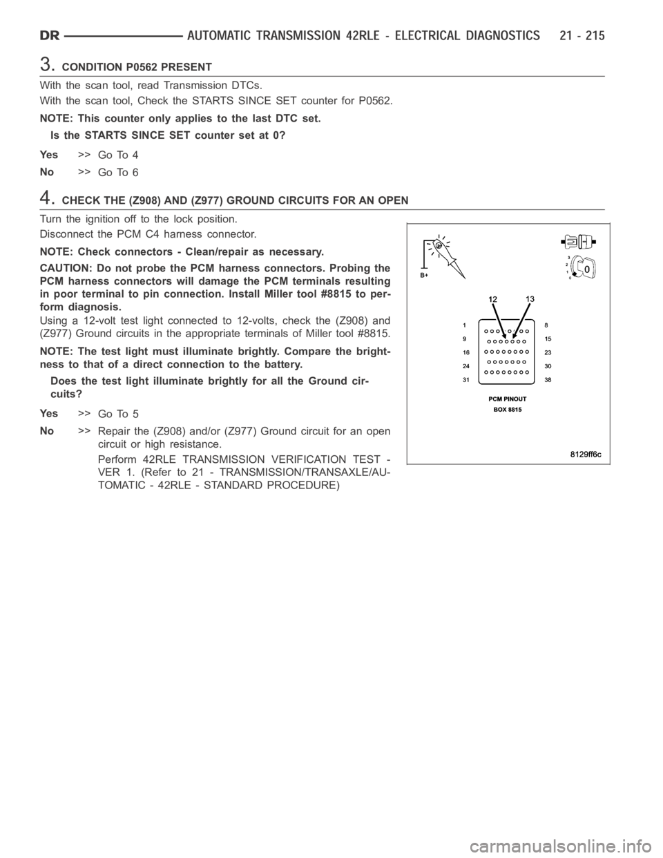
4.CHECK THE (Z908) AND (Z977) GROUND CIRCUITS FOR AN OPEN
Turn the ignition off to the lock position.
Disconnect the PCM C4 harness connector.
NOTE: Check connectors - Clean/repair as necessary.
CAUTION: Do not probe the PCM harness connectors. Probing the
PCM harness connectors will damage the PCM terminals resulting
in poor terminal to pin connection. Install Miller tool #8815 to per-
form diagnosis.
Using a 12-volt test light connected to 12-volts, check the (Z908) and
(Z977) Ground circuits in the appropriate terminals of Miller tool #8815.
NOTE: The test light must illuminate brightly. Compare the bright-
ness to that of a direct connection to the battery.
Does the test light illuminate brightly for all the Ground cir-
cuits?
Ye s>>
Go To 5
No>>
Repair the (Z908) and/or (Z977) Ground circuit for an open
circuit or high resistance.
Perform 42RLE TRANSMISSION VERIFICATION TEST -
VER 1. (Refer to 21 - TRANSMISSION/TRANSAXLE/AU-
TOMATIC - 42RLE - STANDARD PROCEDURE)
Page 2737 of 5267
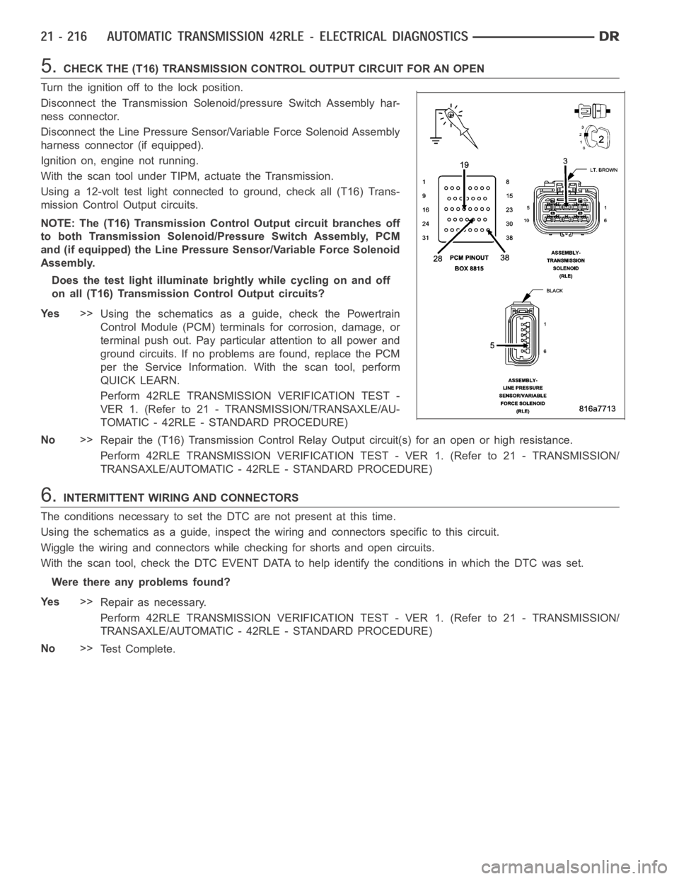
5.CHECK THE (T16) TRANSMISSION CONTROL OUTPUT CIRCUIT FOR AN OPEN
Turn the ignition off to the lock position.
Disconnect the Transmission Solenoid/pressure Switch Assembly har-
ness connector.
Disconnect the Line Pressure Sensor/Variable Force Solenoid Assembly
harness connector (if equipped).
Ignition on, engine not running.
With the scan tool under TIPM, actuate the Transmission.
Using a 12-volt test light connected to ground, check all (T16) Trans-
mission Control Output circuits.
NOTE: The (T16) Transmission Control Output circuit branches off
to both Transmission Solenoid/Pressure Switch Assembly, PCM
and (if equipped) the Line Pressure Sensor/Variable Force Solenoid
Assembly.
Does the test light illuminate brightly while cycling on and off
on all (T16) Transmission Control Output circuits?
Ye s>>
Using the schematics as a guide, check the Powertrain
Control Module (PCM) terminals for corrosion, damage, or
terminal push out. Pay particular attention to all power and
ground circuits. If no problems are found, replace the PCM
per the Service Information.With the scan tool, perform
QUICK LEARN.
Perform 42RLE TRANSMISSION VERIFICATION TEST -
VER 1. (Refer to 21 - TRANSMISSION/TRANSAXLE/AU-
TOMATIC - 42RLE - STANDARD PROCEDURE)
No>>
Repair the (T16) Transmission Control Relay Output circuit(s) for an openor high resistance.
Perform 42RLE TRANSMISSION VERIFICATION TEST - VER 1. (Refer to 21 - TRANSMISSION/
TRANSAXLE/AUTOMATIC - 42RLE - STANDARD PROCEDURE)
6.INTERMITTENT WIRING AND CONNECTORS
The conditions necessary to set the DTC are not present at this time.
Using the schematics as a guide, inspect the wiring and connectors specifictothiscircuit.
Wiggle the wiring and connectors while checking for shorts and open circuits.
With the scan tool, check the DTC EVENT DATA to help identify the conditionsin which the DTC was set.
Were there any problems found?
Ye s>>
Repair as necessary.
Perform 42RLE TRANSMISSION VERIFICATION TEST - VER 1. (Refer to 21 - TRANSMISSION/
TRANSAXLE/AUTOMATIC - 42RLE - STANDARD PROCEDURE)
No>>
Te s t C o m p l e t e .
Page 2739 of 5267
P0604-INTERNAL CONTROL MODULE RAM
For a complete wiring diagramRefer to Section 8W.
When Monitored:
One time after the ignition key is turned to the run position.
Set Condition:
The read value does not match the written value in any RAM location.
Possible Causes
PCM - INTERNAL ERROR
Always perform the Pre-Diagnostic Troubleshooting procedure before proceeding. (Refer to 21 - TRANSMIS-
SION/TRANSAXLE/AUTOMATIC - 42RLE - STANDARD PROCEDURE)
Theory of Operation
After the controller is reset, the microprocessor checks the integrity ofeach RAM location by writing to it and read-
ing back from it. The read value should be the same as the written value. MIL on after 10 seconds of vehicle oper-
ation and transmission will be placed in limp-in.
Diagnostic Test
1.PCM - INTERNAL ERROR
If there are no possible causes remaining, view repair.
Repair
Using the schematics as a guide, check the Powertrain Control Module (PCM)terminals for corrosion,
damage, or terminal push out. Pay particular attention to all power and ground circuits. Check for Ser-
vice Information Tune-ups or Service Bulletins for any possible causes that may apply. If no problems
are found, replace the PCM per the Service Information. With the scan tool,perform QUICK LEARN.
Perform 42RLE TRANSMISSION VERIFICATION TEST - VER 1. (Refer to 21 - TRANSMISSION/
TRANSAXLE/AUTOMATIC - 42RLE - STANDARD PROCEDURE)
Page 2740 of 5267
P0605-INTERNAL CONTROL MODULE ROM
For a complete wiring diagramRefer to Section 8W.
When Monitored:
One time after the ignition key is turned to the run position.
Set Condition:
If the ROM checksum does not match a known constant.
Possible Causes
PCM - INTERNAL ERROR
Always perform the Pre-Diagnostic Troubleshooting procedure before proceeding. (Refer to 21 - TRANSMIS-
SION/TRANSAXLE/AUTOMATIC - 42RLE - STANDARD PROCEDURE)
Theory of Operation
After the controller is reset, the microprocessor checksthe integrity ofthe program memory (ROM). A checksum is
calculated by adding all used bytes in the program memory. The sum should bethesameasaknownconstant
stored in memory. MIL on after 10 seconds of vehicle operation and transmission will be placed in limp-in.
Diagnostic Test
1.PCM - INTERNAL ERROR
Using the schematics as a guide, inspect the wiring and connectors. Repairas necessary. Pay particular attention
to all power and ground circuits.
If there are no possible causes remaining, view repair.
Repair
Using the schematics as a guide, check the Powertrain Control Module (PCM)terminals for corrosion,
damage, or terminal push out. Pay particular attention to all power and ground circuits. Check for Ser-
vice Information Tune-ups or Service Bulletins for any possible causes that may apply. If no problems
are found, replace the PCM per the Service Information. With the scan tool,perform QUICK LEARN.
Perform 42RLE TRANSMISSION VERIFICATION TEST - VER 1. (Refer to 21 - TRANSMISSION/
TRANSAXLE/AUTOMATIC - 42RLE - STANDARD PROCEDURE)
Page 2741 of 5267
P0613-INTERNAL TRANSMISSION PROCESSOR
For a complete wiring diagramRefer to Section 8W.
When Monitored:
After the ignition key is turned to the run position and 60 seconds thereafter.
Set Condition:
Either of the following conditions occur 3 times in less than 590 milliseconds: The watchdog line remains high
after the watchdog test or the transmission relay coil is energized and remains on after the watchdog delay
expires.
Possible Causes
PCM - INTERNAL ERROR
Always perform the Pre-Diagnostic Troubleshooting procedure before proceeding. (Refer to 21 - TRANSMIS-
SION/TRANSAXLE/AUTOMATIC - 42RLE - STANDARD PROCEDURE)
Theory of Operation
The internal watchdog is a separate hardware circuit which continuously monitors the microprocessor. To make sure
the transmission is operating properly, the watchdog must receive a signal from the microprocessor within a specific
time window. MIL on after 10 seconds of vehicle operation and transmissionwill be placed in limp-in.
Diagnostic Test
1.PCM - INTERNAL ERROR
Using the schematics as a guide, inspect the wiring and connectors. Repairas necessary. Pay particular attention
to all power and ground circuits.
If there are no possible causes remaining, view repair.
Repair
Using the schematics as a guide, check the Powertrain Control Module (PCM)terminals for corrosion,
damage, or terminal push out. Pay particular attention to all power and ground circuits. Check for Ser-
vice Information Tune-ups or Service Bulletins for any possible causes that may apply. If no problems
are found, replace the PCM per the Service Information. With the scan tool,perform QUICK LEARN.
Perform 42RLE TRANSMISSION VERIFICATION TEST - VER 1. (Refer to 21 - TRANSMISSION/
TRANSAXLE/AUTOMATIC - 42RLE - STANDARD PROCEDURE)
Page 2743 of 5267
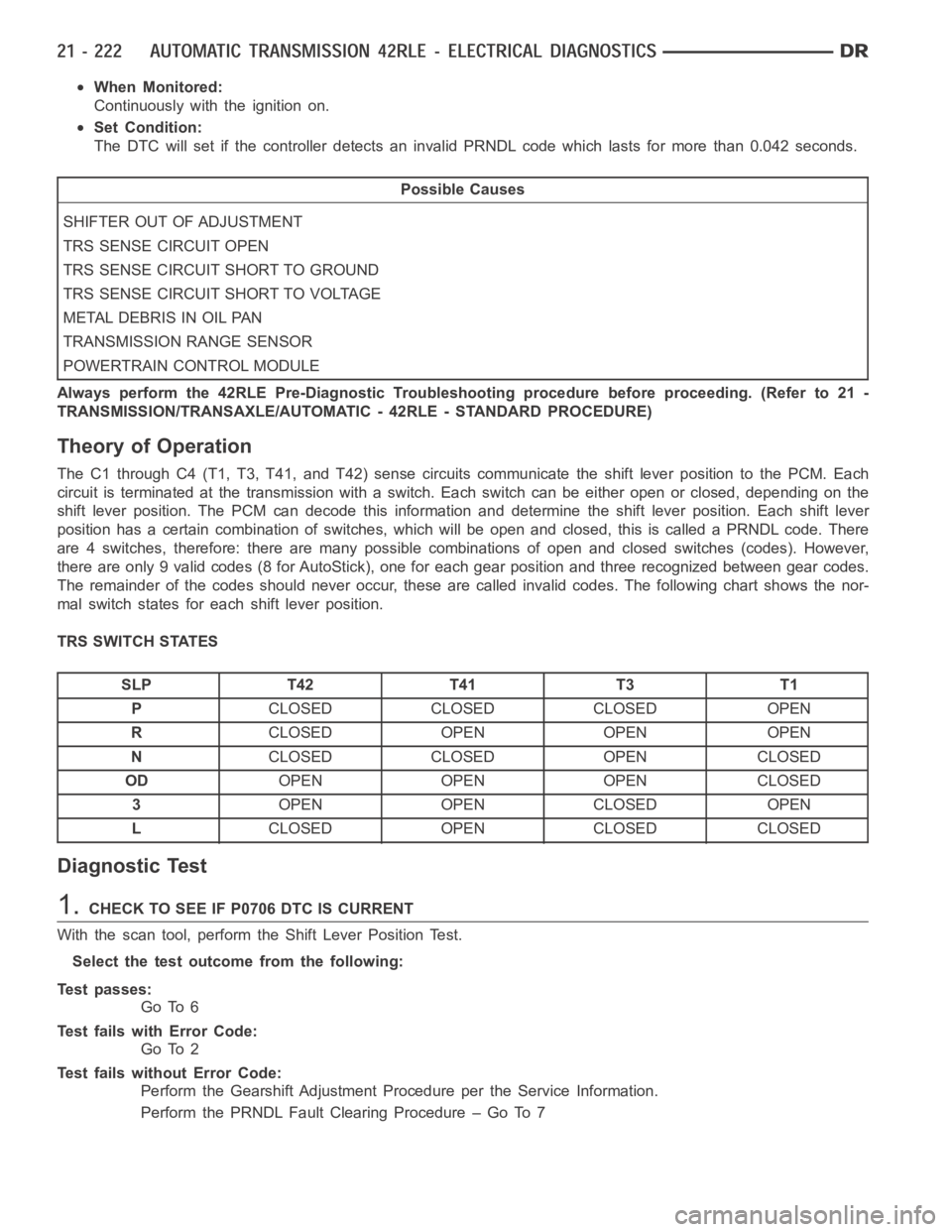
When Monitored:
Continuously with the ignition on.
Set Condition:
The DTC will set if the controller detects an invalid PRNDL code which lastsfor more than 0.042 seconds.
Possible Causes
SHIFTER OUT OF ADJUSTMENT
TRS SENSE CIRCUIT OPEN
TRS SENSE CIRCUIT SHORT TO GROUND
TRS SENSE CIRCUIT SHORT TO VOLTAGE
METAL DEBRIS IN OIL PAN
TRANSMISSION RANGE SENSOR
POWERTRAIN CONTROL MODULE
Always perform the 42RLE Pre-Diagnostic Troubleshooting procedure before proceeding. (Refer to 21 -
TRANSMISSION/TRANSAXLE/AUTOMATIC - 42RLE - STANDARD PROCEDURE)
Theory of Operation
The C1 through C4 (T1, T3, T41, and T42) sense circuits communicate the shift lever position to the PCM. Each
circuit is terminated at the transmission with a switch. Each switch can beeither open or closed, depending on the
shift lever position. The PCM can decode this information and determine the shift lever position. Each shift lever
position has a certain combination of switches, which will be open and closed, this is called a PRNDL code. There
are 4 switches, therefore: there are many possible combinations of open and closed switches (codes). However,
there are only 9 valid codes (8 for AutoStick), one for each gear position and three recognized between gear codes.
The remainder of the codes should never occur, these are called invalid codes. The following chart shows the nor-
mal switch states for each shift lever position.
TRS SWITCH STATES
SLP T42 T41 T3 T1
PCLOSED CLOSED CLOSED OPEN
RCLOSED OPEN OPEN OPEN
NCLOSED CLOSED OPEN CLOSED
ODOPEN OPEN OPEN CLOSED
3OPEN OPEN CLOSED OPEN
LCLOSED OPEN CLOSED CLOSED
Diagnostic Test
1.CHECK TO SEE IF P0706 DTC IS CURRENT
With the scan tool, perform the Shift Lever Position Test.
Select the test outcome from the following:
Test passes:
Go To 6
Test fails with Error Code:
Go To 2
Test fails without Error Code:
Perform the Gearshift Adjustment Procedure per the Service Information.
Perform the PRNDL Fault Clearing Procedure – Go To 7
Page 2744 of 5267
2.CHECK THE TRANSMISSION SOLENOID/TRS ASSEMBLY
Turn the ignition off to the lock position.
Remove the Ignition Switch Feed fuse from the TIPM.
CAUTION: Removal of the Ignition Switch Feed fuse from the TIPM will prevent the vehicle from being
startedingear.
WARNING: The Ignition Switch Feed fuse must be removed from the TIPM. Failure to do so can result in
personal injury or death.
Install the Transmission Simulator,Miller tool #8333 and the ElectronicTransmission Adapter kit.
Ignition on, engine not running.
With the scan tool, perform the Shift Lever Position Test.
When the scan tool instructs you to put the Gear Selector in a particular position, you must do so using the selector
switch on the Transmission Simulator.
The LED for the gear position in question must be illuminated on the Transmission Simulator prior to pressing
ENTERon the scan tool.
NOTE: When the scan tool requests the O/D off button be depressed, you must use the O/D OFF button in
the vehicle or you will fail the Shift Lever Position Test with an error code11 or OD-TOW/HALL STUCK
OPEN.
NOTE: If the Shift Lever Position test fails, make sure to note the identification of the TRS Sense circuit for
future reference.
Did the Shift Lever Position test pass?
Ye s>>
Remove the Oil Pan and Main Valve Body Assembly per the Service Information. Check for metal debris
on top of the TRS Assembly. If debris is present, determine the cause of the debris and repair the trans-
mission as necessary. If no problems are found, replace the Transmission TRS Assembly per the Ser-
vice Information.
Perform the PRNDL Fault Clearing Procedure – Go To 7
No>>
Go To 3
3.TRS SENSE CIRCUIT OPEN
Turn the ignition off to the lock position.
Disconnect the Transmission Simulator, Miller tool #8333.
Disconnect the PCM harness connectors and install Miller tool #8815.
CAUTION: Do not probe the PCM harness connectors. Probing the PCM harness connectors will damage
the PCM terminals resulting in poor terminal to pin connection. Install Miller tool #8815 to perform diagno-
sis.
Measure the resistance of the identified (T1, T3, T41, or T42) TRS Sense circuit, from the Transmission Solenoid/
TRS Assembly harness connector to theappropriate terminal of Miller tool#8815.
Is the resistance above 5.0 ohms?
Ye s>>
Repair the identified (T1, T3, T41, or T42) TRS Sense circuit for an open.
Perform the PRNDL Fault Clearing Procedure – Go To 7
No>>
Go To 4
Page 2745 of 5267
4.TRS SENSE CIRCUIT SHORT TO GROUND
Measure the resistance between ground and the identified (T1, T3, T41, or T42) TRS Sense circuit.
Is the resistance below 5.0 ohms?
Ye s>>
Repair the identified (T1, T3, T41, or T42) TRS Sense circuit for a short to ground.
Perform the PRNDL Fault Clearing Procedure – Go To 7
No>>
Go To 5
5.TRS SENSE CIRCUIT SHORT TO OTHER CIRCUITS
Measure the resistance between the identified (T1, T3, T41, or T42) TRS Sense circuit and all other circuits in the
Transmission Solenoid/TRS Assembly harness connector.
Is the resistance below 100k ohms between the identified (T1, T3, T41, or T42) TRS Sense circuit and
any other circuit(s) in the Transmission Solenoid/TRS Assembly harness connector?
Ye s>>
Repair the identified (T1, T3, T41, or T42) TRS Sense circuit for a short to other circuit(s).
Perform the PRNDL Fault Clearing Procedure – Go To 7
No>>
Using the schematics as a guide, check the Powertrain Control Module (PCM)terminals for corrosion,
damage, or terminal push out. Pay particular attention to all power and ground circuits. If no problems
are found, replace the PCM per the Service Information. With the scan tool,perform QUICK LEARN.
Perform the PRNDL Fault Clearing Procedure – Go To 7
6.INTERMITTENT WIRING AND CONNECTORS
The conditions necessary to set the DTC are not present at this time.
Using the schematics as a guide, inspect the wiring and connectors specifictothiscircuit.
Wiggle the wiring and connectors while checking for shorted and open circuits.
With the scan tool, check the DTC EVENT DATA to help identify the conditionsin which the DTC was set.
Were there any problems found?
Ye s>>
Repair as necessary.
Perform the PRNDL Fault Clearing Procedure – Go To 7
No>>
Te s t C o m p l e t e .
7.PRNDL FAULT CLEARING PROCEDURE
With the scan tool, erase Transmission DTCs.
Cycle the ignition off, then start the vehicle.
Firmly apply the brakes and shift into Overdrive.
NOTE: Vehicle must remain in Overdrive for at least 3.0 seconds.
With the brakes firmly applied, shift slowly through all gears (PRNDL) as least three times, pausing momentarily in
each gear.
NOTE: If all the PRNDL lights box individually then the error was cleared.
Shift into park and turn the ignition off to the lock position.
Ignition on, engine not running.
With the scan tool, read Transmission DTCs.
Does the DTC P0706 reset, or do all the PRNDL indicators remain boxed in parkor neutral?
Ye s>>
Return to the symptom list and perform diagnostics for P0706-TRANSMISSION RANGE SENSOR
RATIONALITY.
Go To 1
No>>
Te s t C o m p l e t e .
Perform 42RLE TRANSMISSION VERIFICATION TEST - VER 1. (Refer to 21 - TRANSMISSION/
TRANSAXLE/AUTOMATIC - 42RLE - STANDARD PROCEDURE)