Page 1782 of 2893
����
S
pecial Tools Required
Dr
iver’s Center Vent
20-105
Dashboard Vent Removal/Installation
Fastener Locations
A
B
:Screw,3
F
astener Loca")
���
����
�(�#�'�����������������������
�������
� �����)����
S
pecial Tools Required
Dr
iver’s Center Vent
20-105
Dashboard Vent Removal/Installation
Fastener Locations
A
B
:Screw,3
F
astener Locations
A
B
:Screw,3
KTC trim tool set SOJATP2014
NOTE: Take care not to scratch the dashboard and
r
elated parts.
1. Remove the subdisplay visor (see page 20- 100).
2. Remove the screws securing the driver’s outer vent (A), then remove the driver’s outer vent from the
subdisplay visor (B).
3. Install the outer vent in the reverse order of removal. N
OTE: Take care not to scratch the dashboard and
related parts.
1. Remove these items: Navigation unit, with navigation system– ’06-08 models (see page 23-155)
– ’09 model (see page 23-355)
Audio unit, without navigation system – ’06-08 models (see page 23-80)
– ’09 model (see page 23-256)
2. Remove the screws securing the driver’s center vent (A), then remove the driver’s center vent from
the center panel (B).
3. Install the center vent in the reverse order of removal.
(cont’d)
08/08/21 15:02:55 61SNR030_200_0107
ProCarManuals.com
DYNOMITE -2009-
Page 1783 of 2893
���
����
����
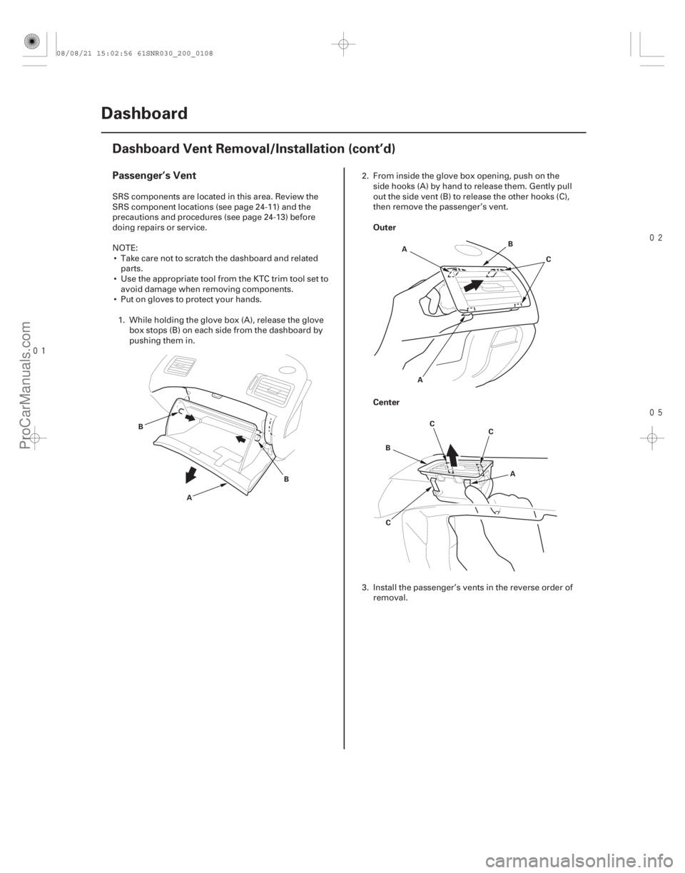
Passenger’s Vent
Outer
Center
20-106Dashboard
Dashboard Vent Removal/Installation (cont’d)
A
B
BAB
C
A
B A
C
C
C
SRS components are located in this area. Review the
SRS component locations (see page 24-11) and the
precautions and procedures (see page 24-13) before
doing repairs or service.
NOTE: Take care not to scratch the dashboard and related parts.
Use the appropriate tool from the KTC trim tool set to avoid damage when removing components.
Put on gloves to protect your hands.
1. While holding the glove box (A), release the glove box stops (B) on each side from the dashboard by
pushing them in. 2. From inside the glove box opening, push on the
side hooks (A) by hand to release them. Gently pull
out the side vent (B) to release the other hooks (C),
then remove the passenger’s vent.
3. Install the passenger’s vents in the reverse order of removal.
08/08/21 15:02:56 61SNR030_200_0108
ProCarManuals.com
DYNOMITE -2009-
Page 1784 of 2893
����
���
�(�#������������������������
��������� �����)���� S
pecial Tools Required
20-10720-107
Glove Box Striker Replacement Dashboard Side Trim R")
���
�(�#�'���������������������������
����� �����)����
���
�(�#�'�����������������������
��������� �����)���� S
pecial Tools Required
20-10720-107
Glove Box Striker Replacement Dashboard Side Trim Removal/
Installation
Fastener Locations
A
:Screw,2
A
B C
D
SRS components are located in this area. Review the
SRS component locations (see page 24-11) and the
precautions and procedures (see page 24-13) before
doing repairs or service.
NOTE: Take care not to scratch the dashboard and
related parts.
1. While holding the glove box, release the glove box stop on each side from the dashboard by pushing
them in.
2. Remove the screws, then remove the glove box striker (A).
3. Install the striker in the reverse order of removal. KTC trim tool set SOJATP2014
NOTE:
Use the appropriate tool from the KTC trim tool set to avoid damage when removing components.
Take care not to scratch the dashboard and related parts.
1. Remove the dashboard side trim (A). –1 Gently pull up the rear edge to release the rearhooks (B).
–2 Pull the trim away to release the front hook (C) from the A-pillar trim (D).
2. Install the side trim in the reverse order of removal.
08/08/21 15:02:56 61SNR030_200_0109
ProCarManuals.com
DYNOMITE -2009-
Page 1785 of 2893
����
�(�#���������������������������������� �����)����
S
pecial Tools Required
Special Tools Required
20-10820-108Dashboard
Side Defogger Vent Trim")
�����(�#�'�����������������������
�������
� �����)����
�(�#�'��������������������������������� �����)����
S
pecial Tools Required
Special Tools Required
20-10820-108Dashboard
Side Defogger Vent Trim Removal/
Installation
Dashboard/Steering Hanger Beam
Removal/Installation
A
B C
KTC trim tool set SOJATP2014
NOTE:
Use the appropriate tool from the KTC trim tool set to avoid damage when removing components.
Take care not to scratch the dashboard and related parts.
1. Insert the trim tool into a gap between the side defogger vent trim (A) and the dashboard (B), and
release the hook (C).
2. Install the side defogger vent trim in the r everse
order of removal. KTC trim tool set SOJATP2014
SRS components are located in this area. Review the
SRS component locations (see page 24-11) and the
precautions and procedures (see page 24-13) before
doing repairs or service.
NOTE:
Use the appropriate tool from the KTC trim tool set to avoid damage when removing components.
Have an assistant help you when removing and installing the das hboard/steering hanger beam.
Take care not to scratch the dashboard, the body and other related parts.
Put on gloves to protect your hands.
1. Do the battery terminal disconnection procedure (see page 22-68), and wait at least 3 minutes before
beginning work.
2. Remove these items: Driver’s dashboard lower cover (see page20-102)
Driver’s dashboard undercover (see page 20- 103)
Passenger’s dashboard undercover (see page 20-104)
Center console (see page 20-92)
Glove box (see page 20-104)
Kick panel, both sides (see page 20-66)
A-pillar trim, both sides (see page 20-69)
Steering column (see page 17-10)
EPS control unit (see page 17-84)
08/08/21 15:02:57 61SNR030_200_0110
ProCarManuals.com
DYNOMITE -2009-
Page 1786 of 2893
���
���
����
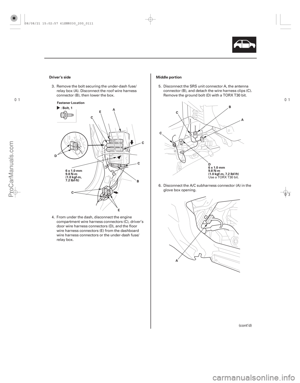
Driver’s side Middle portion
20-109
Fastener Location
6x1.0mm
9.8 N·m
(1.0 kgf·m,
7.2 lbf·ft) A
C
B
D E
:Bolt,1
C
E C
C A
B
D
6x1.0mm
9.8 N·m
(1.0 kgf·m, 7.2 lbf·ft)
C
C
A
3. Remove the bolt securing the under-dash fuse/ relay box (A). Disconnect the roof wire harness
connector (B), then lower the box.
4. From under the dash, disconnect the engine compartment wire harness connectors (C), driver’s
door wire harness connectors (D), and the floor
wire harness connectors (E) from the dashboard
wire harness connectors or the under-dash fuse/
relay box. 5. Disconnect the SRS unit connector A, the antenna
connector (B), and detach the wire harness clips (C).
Remove the ground bolt (D) with a TORX T30 bit.
6. Disconnect the A/C subharness connector (A) in the glove box opening.
(cont’d)
Use a TORX T30 bit.
08/08/21 15:02:57 61SNR030_200_0111
ProCarManuals.com
DYNOMITE -2009-
Page 1787 of 2893
��������
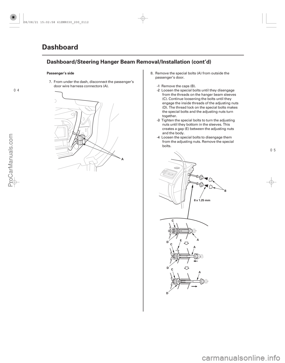
Passenger’s side
20-110 Dashboard
Dashboard/Steering Hanger Beam Removal/Installation (cont’d)
A
A
B
C
D E
A
C
A
C
D
D 8x1.25mm
7. From under the dash, disconnect the passenger’s
door wire harness connectors (A). 8. Remove the special bolts (A) from outside the
passenger’s door.
–1 Remove the caps (B).
–2 Loosen the special bolts until they disengage from the threads on the hanger beam sleeves
(C). Continue loosening the bolts until they
engage the inside threads of the adjusting nuts
(D). The thread lock on the special bolts makes
the special bolts and the adjusting nuts turn
together.
–3 Tighten the special bolts to turn the adjusting nuts until they bottom in the sleeves. This
creates a gap (E) between the adjusting nuts
and the body.
–4 Loosen the special bolts to disengage them from the adjusting nuts. Remove the special
bolts.
08/08/21 15:02:58 61SNR030_200_0112
ProCarManuals.com
DYNOMITE -2009-
Page 1788 of 2893
����
��������
20-111
A
B
C
BC
A
21 mm (0.83 in.) 6x1.0mm
9.8 N·m
(1.0 kgf·m,
7.2 lbf·ft)
A
B
D
D
8x1.25mm
22 N·m
(2.2 kgf·m, 16 lbf·ft)
BB
D
D
6x1.0mm
9.8 N·m
(1.0 kgf·m,
7.2 lbf·ft)
C
8x1.25mm
22 N·m
(2.2 kgf·m, 16 lbf·ft)
Fastener Locations
:Bolt,3 :Bolt,1 :Bolt,4
B CD
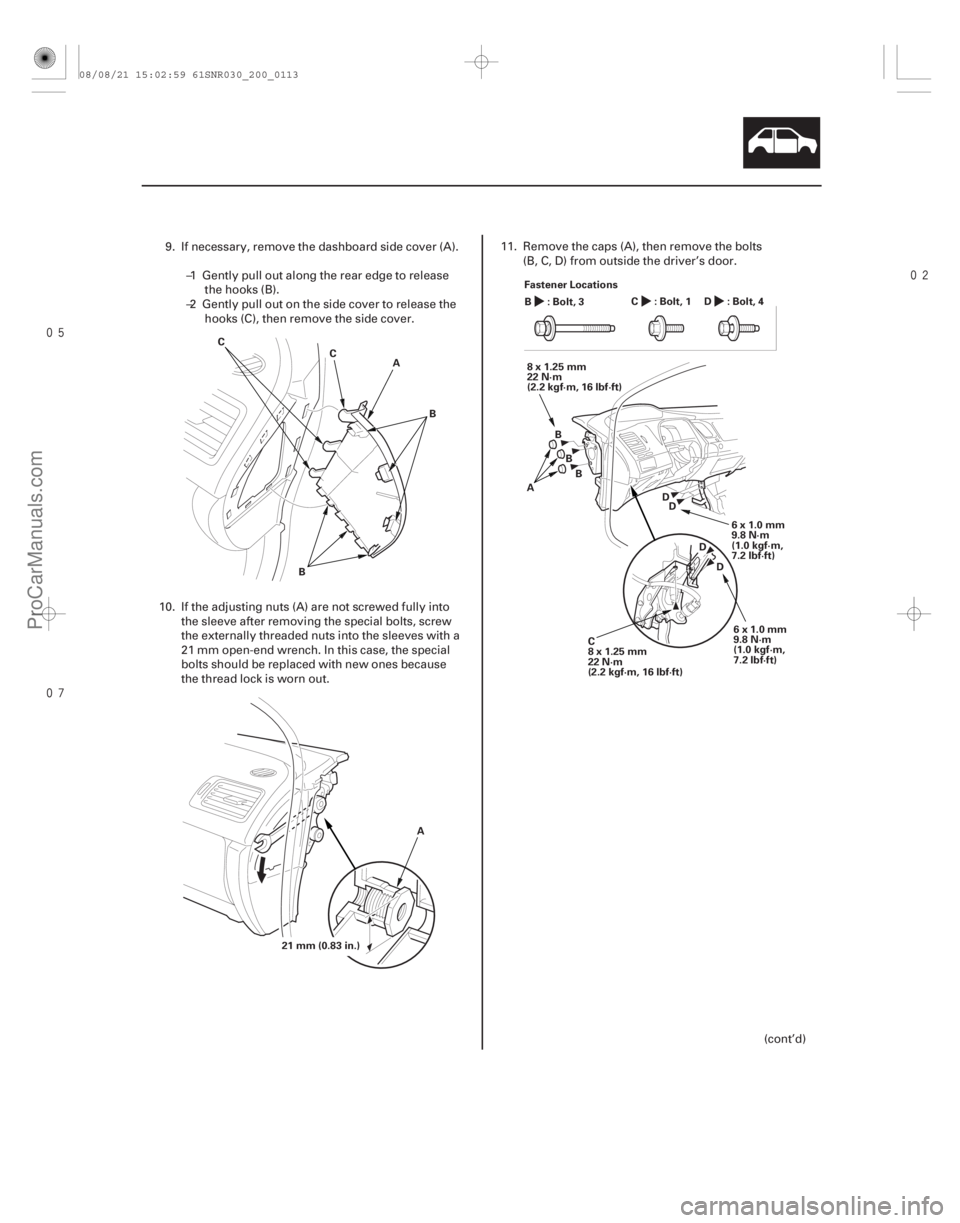
9. If necessary, remove the dashboard side cover (A).
–1 Gently pull out along the rear edge to releasethe hooks (B).
–2 Gently pull out on the side cover to release the hooks (C), then remove the side cover.
10. If the adjusting nuts (A) are not screwed fully into the sleeve after removing the special bolts, screw
the externally threaded nuts into the sleeves with a
21 mm open-end wrench. In this case, the special
bolts should be replaced with new ones because
the thread lock is worn out. 11. Remove the caps (A), then remove the bolts
(B, C, D) from outside the driver’s door.
(cont’d)
08/08/21 15:02:59 61SNR030_200_0113
ProCarManuals.com
DYNOMITE -2009-
Page 1789 of 2893
�����
��
20-112Dashboard
Dashboard/Steering Hanger Beam Removal/Installation (cont’d)
A
B B
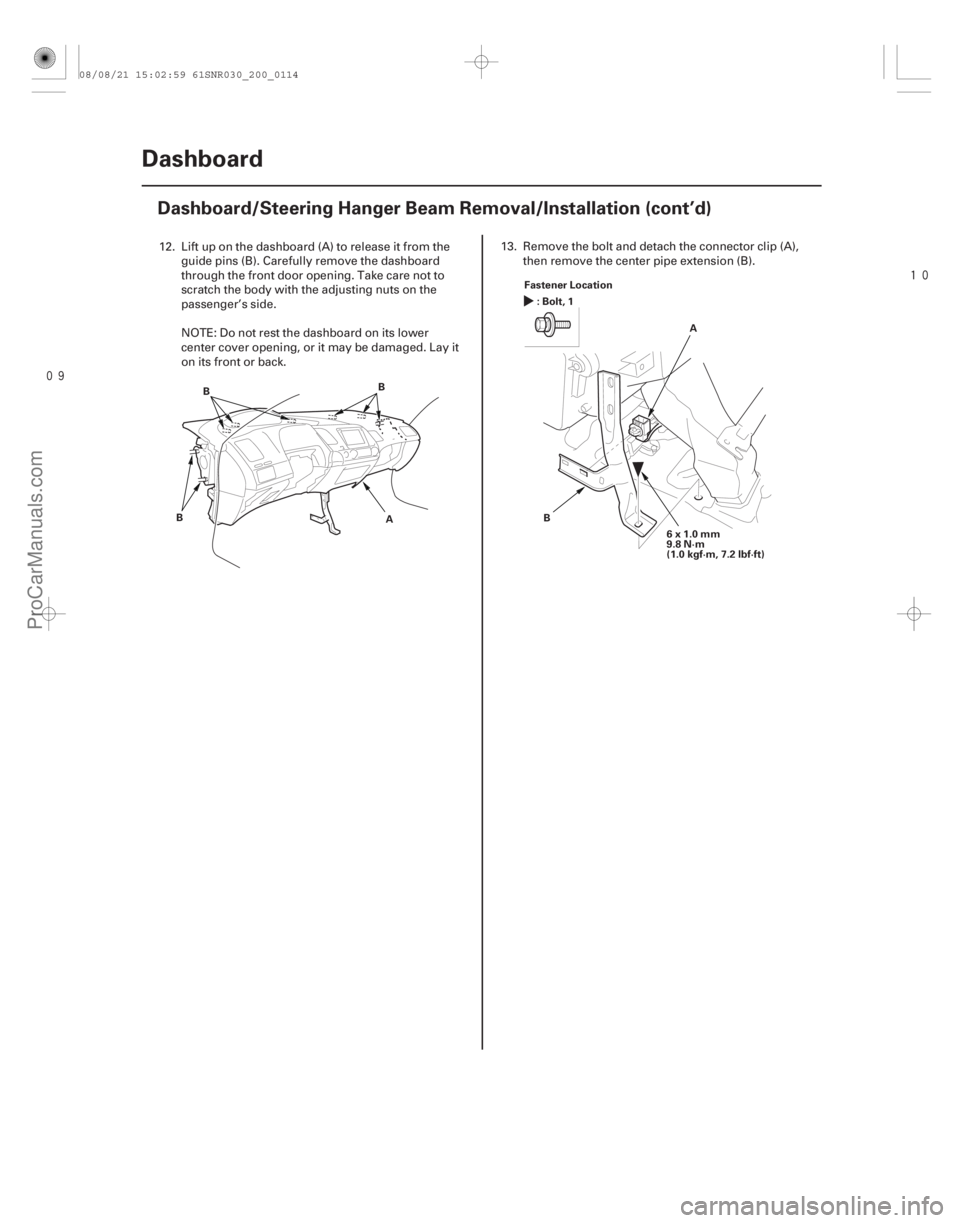
BFastener Location
A
B
:Bolt,1
6x1.0mm
9.8 N·m
(1.0 kgf·m, 7.2 lbf·ft)
12. Lift up on the dashboard (A) to release it from theguide pins (B). Carefully remove the dashboard
through the front door opening. Take care not to
scratch the body with the adjusting nuts on the
passenger’s side.
NOTE: Do not rest the dashboard on its lower
center cover opening, or it may be damaged. Lay it
on its front or back. 13. Remove the bolt and detach the connector clip (A),
then remove the center pipe extension (B).
08/08/21 15:02:59 61SNR030_200_0114
ProCarManuals.com
DYNOMITE -2009-