Page 1771 of 2893
����
��������
20-94Consoles
Center Console Removal/Installation (cont’d)
A
B
C
B
A
B A
BC
8. Slide both front seats all the way back, and recline
the seat-back fully.
9. Slide the center console (A) rearward to release the pins (B) from the bracket (C).
10. Lift up the rear of the console (A), and remove it from the dashboard.
11. If equipped, disconnect the seat heater switch connectors (B). 12. Install the console in the reverse order of removal,
and note these items:
Make sure each connector is plugged in properly.
If the clips are damaged or stress-whitened, replace them with new ones.
Push the clips and the hooks into place securely.
When installing the center console panel, install the tabs (A) into the notch (B) of the parking brake
base frame (C).
08/08/21 15:02:48 61SNR030_200_0096
ProCarManuals.com
DYNOMITE -2009-
Page 1772 of 2893
����
S
pecial Tools Required
20-95
Center Console Disassembly/Reassembly
Fastener Locations
:TORXScrew,8
A A
BC
D
E F
G
H
I
I
A
A
B
C
D")
����
����
����
�(�#�'�����������������
�����
�������
�"�����)����
S
pecial Tools Required
20-95
Center Console Disassembly/Reassembly
Fastener Locations
:TORXScrew,8
A A
BC
D
E F
G
H
I
I
A
A
B
C
D
KTC trim tool set SOJATP2014
NOTE:
Use the appropriate tool from the KTC trim tool set to
avoid damage when removing components.
Take care not to scratch the center console, the dashboard, and related parts.
1. Remove the center console (see page 20-92).
2. Remove the center console armrest (see page 20-96).
3. Remove the screws with a TORX T20 bit, and disconnect the console accessory power socket
connector (A). 4
. Release the hooks (A) and the pins (B), then
separate the left console side panel (C), the right
console side panel (D), the console beverage holder
(E) and the console box (F). If equipped, detach the
harness clips (G), then remove the console
subharness (H) from the hooks (I).
5. Release the hooks (A, B), then separate the console upper box (C) and the console lower box (D).
6. Assemble the console in the reverse order of disassembly, and make sure the console
subharness connector is plugged in properly.
08/08/21 15:02:49 61SNR030_200_0097
ProCarManuals.com
DYNOMITE -2009-
Page 1775 of 2893
����
S
pecial Tools Required
20-98 Dashboard
Instrument Panel Removal/Installation
Fastener Locations
:Screw,3 F
astener Locations
:Clip,2")
���
����
����
�(�#�'�������������������������������
� �����)����
S
pecial Tools Required
20-98 Dashboard
Instrument Panel Removal/Installation
Fastener Locations
:Screw,3 F
astener Locations
:Clip,2
A
Fastener Locations : Clip, 6
A
B C
KTC trim tool set SOJATP2014
NOTE:
Take care not to scratch the instrument panel and
related parts.
Use the appropriate tool from the KTC trim tool set to avoid damage when removing components.
1. Remove these items:
Subdisplay visor (see page 20-100)
Navigation unit, with navigation system– ’06-08 models (see page 23-155)
– ’09 model (see page 23-355)
Audio unit, without navigation system – ’06-08 models (see page 23-80)
– ’09 model (see page 23-256)
2. Remove the screws. 3
. Detach the clips along the lower edge of the
instrument panel (A).
4. Detach the clips along the upper edge of the instrument panel (A). Gently pull out the instrument
panel to release the hooks (B) from the holder (C) of
the gauge control module.
5. Install the instrument panel in the reverse order of removal, and note these items:
If the clips are damaged or stress-whitened, replace them with new ones.
Push the clips into place securely.
08/08/21 15:02:52 61SNR030_200_0100
ProCarManuals.com
DYNOMITE -2009-
Page 1776 of 2893
���
����
�(�#�'��������������������������������� �����)�
��
S
pecial Tools Required
20-99
Gauge Control Module (Speedo) Trim Removal/Installation
Fastener Locations
:Clip,4
AA Fa
stener Locations
: Clip, 5
A A A
B
B
C
KTC trim tool set SOJATP2014
NOTE:
Take care not to scratch the dashboard and related
parts.
Use the appropriate tool from the KTC trim tool set to avoid damage when removing components.
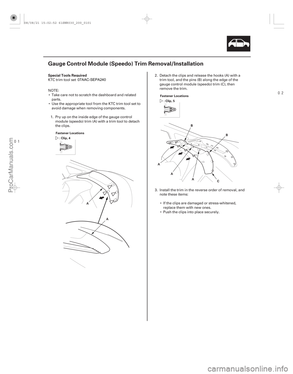
1. Pry up on the inside edge of the gauge control module (speedo) trim (A) with a trim tool to detach
the clips. 2
. Detach the clips and release the hooks (A) with a
trim tool, and the pins (B) along the edge of the
gauge control module (speedo) trim (C), then
remove the trim.
3. Install the trim in the reverse order of removal, and note these items:
If the clips are damaged or stress-whitened, replace them with new ones.
Push the clips into place securely.
08/08/21 15:02:52 61SNR030_200_0101
ProCarManuals.com
DYNOMITE -2009-
Page 1777 of 2893
���
����
�(�#�'�����������������������������
��� �����)����
S
pecial Tools Required
20-100 Dashboard
Subdisplay Visor Removal/Installation
Fastener Location
:Screw,1 Fa
stener Locations
:Clip,4
B, E
A B
C
B BF
D
E
D
KTC trim tool set SOJATP2014
NOTE:
Put on gloves to protect your hands.
Take care not to scratch the dashboard and related parts.
Use the appropriate tool from the KTC trim tool set to avoid damage when removing components.
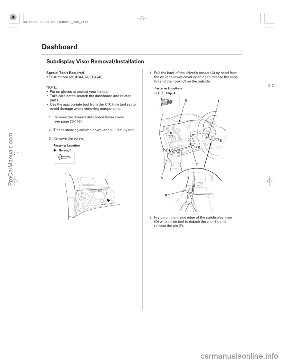
1. Remove the driver’s dashboard lower cover (see page 20-102).
2. Tilt the steering column down, and pull it fully out.
3. Remove the screw. 4
. Pull the back of the driver’s pocket (A) by hand from
the driver’s lower cover opening to release the clips
(B) and the hook (C) on the outside.
5. Pry up on the inside edge of the subdisplay visor (D) with a trim tool to detach the clip (E), and
release the pin (F).
08/08/21 15:02:53 61SNR030_200_0102
ProCarManuals.com
DYNOMITE -2009-
Page 1779 of 2893
���
����
�(�#�'�����������������������
�������
� �����)�
��
S
pecial Tools Required
20-102 Dashboard
Driver’s Dashboard Lower Cover Removal/Installation
A
Fastener Locations
:Clip,3 F
astener Locations
: Clip, 5
AB
C
KTC trim tool set SOJATP2014
NOTE:
Use the appropriate tool from the KTC trim tool set to
avoid damage when removing components.
Take care not to scratch the dashboard and related parts.
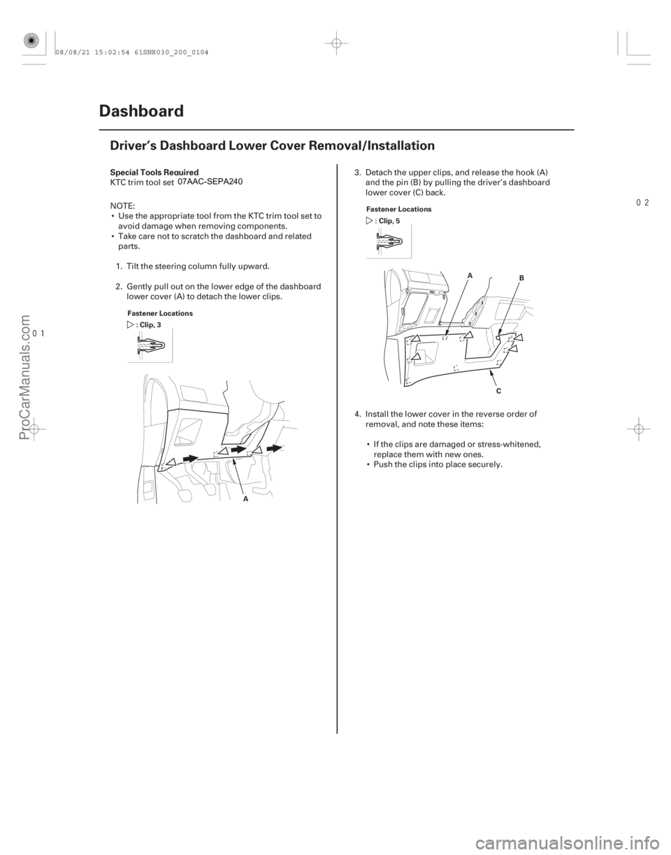
1. Tilt the steering column fully upward.
2. Gently pull out on the lower edge of the dashboard lower cover (A) to detach the lower clips. 3
. Detach the upper clips, and release the hook (A)
and the pin (B) by pulling the driver’s das hboard
lower cover (C) back.
4. Install the lower cover in the reverse order of removal, and note these items:
If the clips are damaged or stress-whitened, replace them with new ones.
Push the clips into place securely.
08/08/21 15:02:54 61SNR030_200_0104
ProCarManuals.com
DYNOMITE -2009-
Page 1780 of 2893
�
�� ���
�(�#������������������������
��������� �����)����
20-10320-103
Driver’s Dashboard Undercover
Removal/Installation Center Pocket Removal/I")
���
�(�#�'�����������������������
�������
� �����)�
�� ���
�(�#�'�����������������������
��������� �����)����
20-10320-103
Driver’s Dashboard Undercover
Removal/Installation Center Pocket Removal/Installation
Fastener Locations
:Clip,2
C DE AB Fastener Locations
:Screw,4
A
NOTE: Take care not to scratch the dashboard and
related parts.1. Remove the driver’s dashboard undercover (A). –1 Turn the lock knob (B) 90 °.
–2 Gently pull down the rear edge to detach theclips.
–3 Pull the undercover away to release the pin (C) from the holder (D).
–4 For some models: If equipped with a foot light illumination, disconnect the foot light
illumination connector (E).
2. Install the undercover in the r everse order of
removal, and note these items:
Make sure the foot light illumination connector is plugged in properly (for some models).
If the clips are damaged or stress-whitened, replace them with new ones.
Push the clips into place securely. NOTE: Take care not to scratch the dashboard and
related parts.
1. Disassemble the dashboard/steering hanger beam (see page 20-114).
2. Remove the screws, then remove the center pocket (A).
3. Install the center pocket in the reverse order of removal.
08/08/21 15:02:54 61SNR030_200_0105
ProCarManuals.com
DYNOMITE -2009-
Page 1781 of 2893
���� ���
����
�(�#����������������������������
���
� �����)����
20-10420-104 Dashboard
Passenger’s Dashboard Undercover
Removal/Installation
Glove")
�����(�#�'�����������������������
�������
� �����)���� ���
����
�(�#�'���������������������������
���
� �����)����
20-10420-104 Dashboard
Passenger’s Dashboard Undercover
Removal/Installation
Glove Box Removal/Installation
Fastener Locations
:Clip,2
B : Clip, 2 C
D FA
E
C C B
B Fastener Locations
:Bolt,2
5x0.8mm
5N·m
(0.5 kgf·m, 4 lbf·ft)
A B
B
NOTE: Take care not to scratch the dashboard and
related parts.
1. Remove the passenger’s dashboard undercover (A). –1 Gently pull out the rear edge to detach the clips(B, C).
–2 Pull the undercover away to release the pins (D) from the holders (E).
–3 For some models: If equipped with a foot light illumination, disconnect the foot light
illumination connector (F).
2. Install the undercover in the r everse order of
removal, and note these items:
Make sure the foot light illumination connector is plugged in properly (for some models).
If the clips are damaged or stress-whitened, replace them with new ones.
Push the clips into place securely. SRS components are located in this area. Review the
SRS component locations (see page 24-11) and the
precautions and procedures (see page 24-13) before
doing repairs or service.
NOTE: Take care not to scratch the dashboard and
related parts.
1. Remove the bolts.
2. While holding the glove box (A), release the glove box stop (B) on each side from the dashboard by
pushing them in, then remove the glove box.
3. Install the glove box in the reverse order of removal.
08/08/21 15:02:55 61SNR030_200_0106
ProCarManuals.com
DYNOMITE -2009-