Page 2095 of 2893
�
��
22-147
Horn Switch Test
A A
B
C
1. Remove the steering column covers (see page
17-9).
2. Disconnect the cable reel 20P connector (A) from")
����
����
�(�#�'�����������������������������
�
�������)�
��
22-147
Horn Switch Test
A A
B
C
1. Remove the steering column covers (see page
17-9).
2. Disconnect the cable reel 20P connector (A) from the dashboard wire harness.
3. Using a jumper wire, connect dashboard wire harness 20P connector terminal No. 10 to body
ground. The horn should sound.
If the horn sounds, go to step 4.
If the horn does not sound, check these items: – No. 12 (15 A) fuse in the under-hood fuse/relay box.
– MICU.
– Horn.
– Anopeninthewire. 4. Reconnect the cable reel 20P connector (A) to the
dashboard wire harness.
5. Remove the driver’s airbag assembly (see page 24-188), and disconnect the horn switch 1P positive
terminal (B) from the cable reel (C).
6. Using a jumper wire, connect the 1P connector to body ground.
If the horn sounds, replace the driver’s airbag assembly.
If the horn does not sound, check these items: – Cable reel.
– Anopeninthewire.
Wire side of
female terminals
08/08/21 14:26:09 61SNR030_220_0149
ProCarManuals.com
DYNOMITE -2009-
Page 2114 of 2893
���
�(�#�'���������������
�������
���
���
�������)����
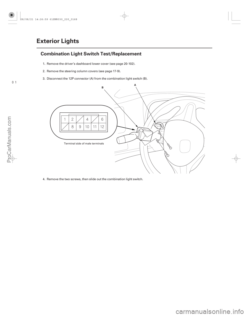
22-166Exterior Lights
Combination Light Switch Test/Replacement
A
B
1. Remove the driver’s dashboard lower cover (see page 20- 102).
2. Remove the steering column covers (see page 17-9).
3. Disconnect the 12P connector (A) from the combination light switch (B).
4. Remove the two screws, then slide out the combination light switch.
Terminal side of male terminals
08/08/21 14:26:59 61SNR030_220_0168
ProCarManuals.com
DYNOMITE -2009-
Page 2151 of 2893
����
�����
�(�#�'���������������������������
�����������)����
�´ �µ �´
�µ
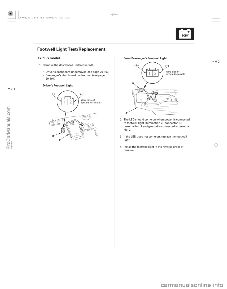
TYPE S model
Driver’s Footwell Light Front Passenger’s Footwell Light
22-201
Footwell Light Test/Replacement
()
()
A
B ()
()
A B
1. Remove the dashboard undercover (A).
Driver’s dashboard undercover (see page 20- 103)
Passenger’s dashboard undercover (see page 20-104)
2. The LED should come on when power is connectedto footwell light illumination 2P connector (B)
terminal No. 1 and ground is connected to terminal
No. 2.
3. If the LED does not come on, replace the footwell light.
4. Install the footwell light in the reverse order of removal.
Wire side of
female terminals Wire side of
female terminals
08/08/21 14:27:52 61SNR030_220_0203
ProCarManuals.com
DYNOMITE -2009-
Page 2181 of 2893
���� �´�µ���
����
�(�#��������������������������������
�������)���
22-23122-231
Wiper/Washer Switch Test Wiper Motor Test
A
B
OFF INT
LO
HI")
���
�����(�#�'�������������������������������
�������)���� �´�µ���
����
�(�#�'�������������������������������
�������)���
22-23122-231
Wiper/Washer Switch Test Wiper Motor Test
A
B
OFF INT
LO
HI Terminal
Position
Mist ON
Washer ON 1
2
345 8
Intermittent dwell
timer turned A
B
Terminal
Position
LOW SPEED
HIGH SPEED 1
2 3
1. Remove the wiper/washer switch (see page 22-234).
2. Disconnect the dashboard wire harness 8P
connector (A) from the wiper/washer switch (B).
3. Check for continuity between the terminals in each switch position according to the table.
4. If the continuity is not as specified, replace the switch. 1. Remove the wiper arms (see page 22-233).
NOTE: Carefully remove the wiper arms so that
they do not touch the hood.
2. Remove the hood seal and cowl cover.
3. Disconnect the 5P connector (A) from the wiper motor (B).
4. Test the motor by connecting battery power and ground according to the table. If the motor does not
run or fails to run smoothly, replace the motor.
5. Connect the battery power to terminal No. 1, and body ground to terminal No. 2 of the 5P connector.
Then connect an analog voltmeter between
terminal No. 1 ( ) and terminal No. 5 ( ). When
the park switch makes contact, the pointer should
swing. If not, replace the motor.
08/08/21 14:28:48 61SNR030_220_0233
ProCarManuals.com
DYNOMITE -2009-
Page 2184 of 2893
���� ���
����
�(�#��������������������������������
� �����)���� Washer reservoir capacity: 4.5 L (4.8 US qt)
22-23422-234
Wipers/Washers
Wiper/Washe")
���
�(�#�'�������������������������������
� �����)���� ���
����
�(�#�'�������������������������������
� �����)���� Washer reservoir capacity: 4.5 L (4.8 US qt)
22-23422-234
Wipers/Washers
Wiper/Washer Switch Replacement Washer Reservoir Replacement
A
B B
D AC
A
9.8 N·m
(1.0 kgf·m,
7.2 lbf·ft)
B
1. Remove the driver’s dashboard lower cover
(see page 20-102).
2. Remove the steering column covers (see page 17-9).
3. Disconnect the dashboard wire harness 8P connector (A) from the wiper/washer switch (B).
4. Remove the two screws, then slide out the wiper/ washer switch.
5. Install the wiper/washer switch in the reverse order of removal. 1. Remove the right inner fender (see page 20-171).
2. Disconnect the 2P connector(s) (A) from the
windshield washer motor (B) and the washer fluid
level switch (C).
3. Disconnect the windshield washer tube (D).
4. Remove the bolts (A) and the clip (B), then remove the washer reservoir.
5. Install the washer reservoir in the reverse order of removal.
08/08/21 14:28:50 61SNR030_220_0236
ProCarManuals.com
DYNOMITE -2009-
Page 2280 of 2893
���
�(�#�'���������������������������������������)����
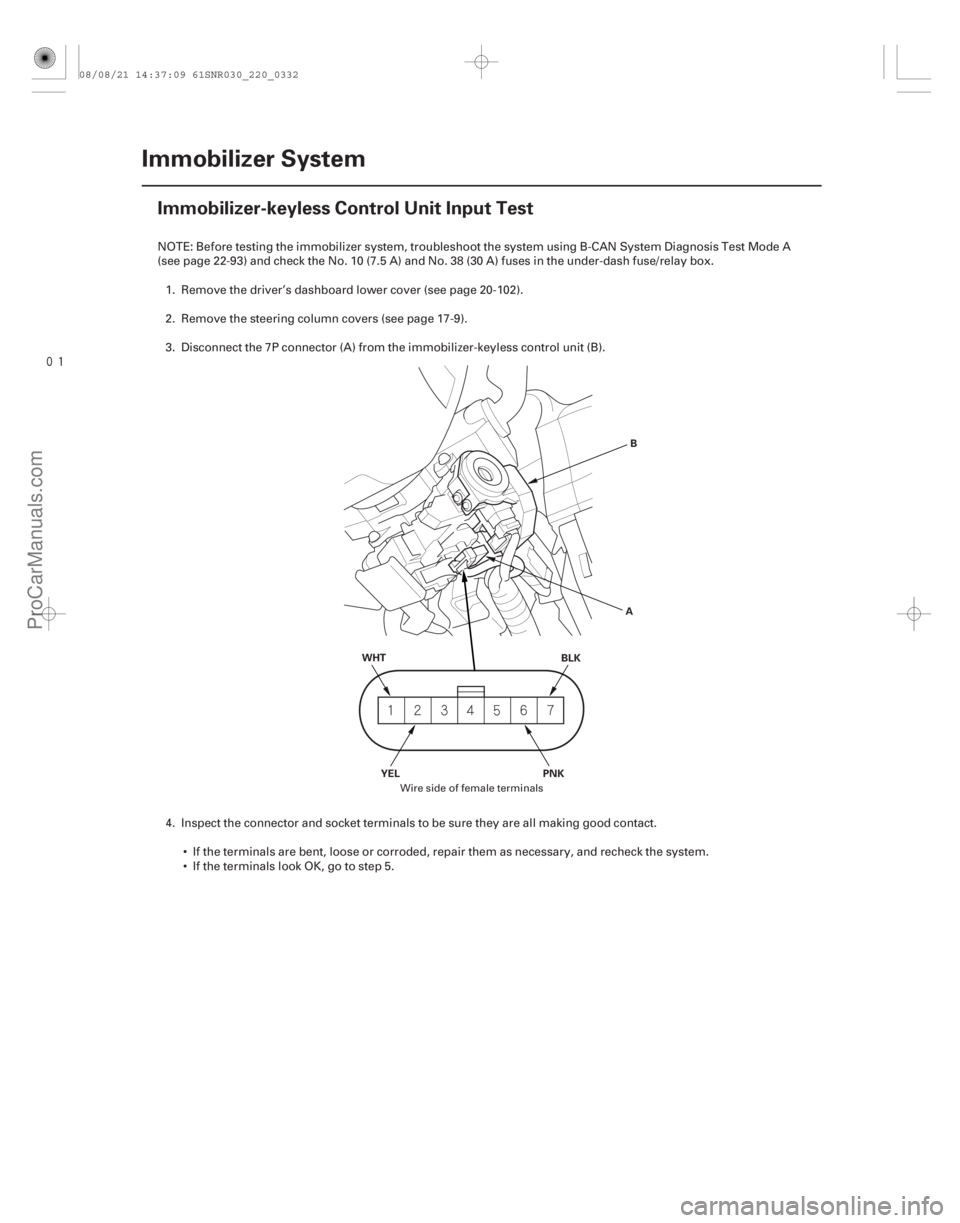
22-330Immobilizer System
Immobilizer-keyless Control Unit Input Test
WHT
BLK
PNK
YEL AB
NOTE: Before testing the immobilizer system, troubleshoot the system using B-CAN System Diagnosis Test Mode A
(see page 22-93) and check the No. 10 (7.5 A) and No. 38 (30 A) fuses in the under-dash fuse/relay box.
1. Remove the driver’s dashboard lower cover (see page 20- 102).
2. Remove the steering column covers (see page 17-9).
3. Disconnect the 7P connector (A) from the immob ilizer-keyless control unit (B).
4. Inspect the connector and socket terminals to be sure they are all making good contact. If the terminals are bent, loose or corroded, repair them as necessary, and recheck the system.
IftheterminalslookOK,gotostep5.
Wire side of female terminals
08/08/21 14:37:09 61SNR030_220_0332
ProCarManuals.com
DYNOMITE -2009-
Page 2282 of 2893
���
�(�#�'��������������������������������� �����)����
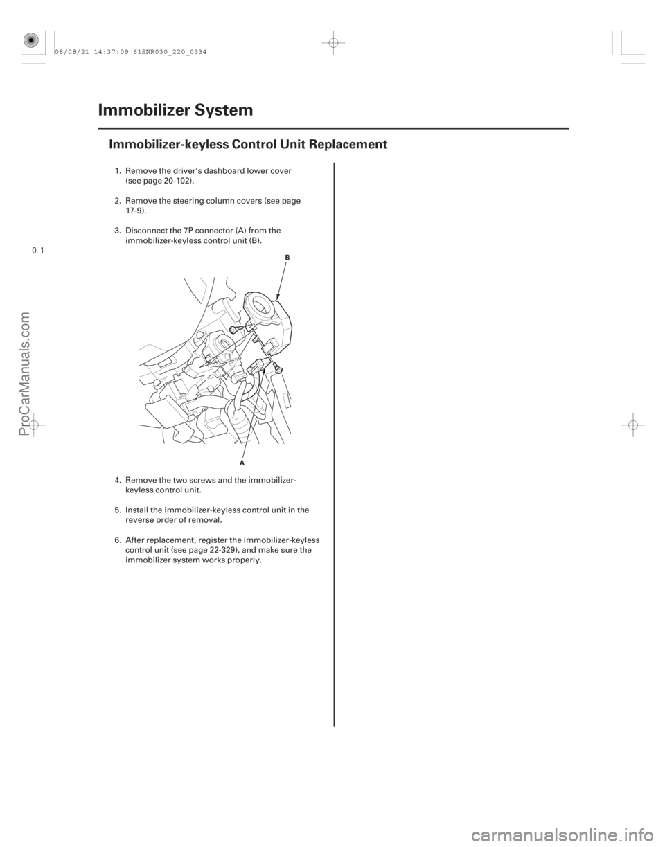
22-332Immobilizer System
Immobilizer-keyless Control Unit Replacement
A
B
1. Remove the driver’s dashboard lower cover
(see page 20-102).
2. Remove the steering column covers (see page 17-9).
3. Disconnect the 7P connector (A) from the immobilizer-keyless control unit (B).
4. Remove the two screws and the immobilizer- keyless control unit.
5. Install the immobilizer-keyless control unit in the reverse order of removal.
6. After replacement, register the immobilizer-keyless control unit (see page 22-329), and make sure the
immobilizer system works properly.
08/08/21 14:37:09 61SNR030_220_0334
ProCarManuals.com
DYNOMITE -2009-
Page 2360 of 2893
���
Without navigation 6 CD type
23-80 Audio System
Audio Unit Removal/Installation
A
B
C
B
A
BSRS components are located in this area. Review")
���
����
�(�#�'�����#�����
�����
�
�
�
���
���
� �����)���
Without navigation 6 CD type
23-80 Audio System
Audio Unit Removal/Installation
A
B
C
B
A
BSRS components are located in this area. Review the
SRS component location (see page 24-11).
Also review the precautions and procedures (see page
24-13) in the SRS section before doing repairs or
service.
NOTE: Put on gloves to protect your hands.
Take care not to scratch the dashboard and related parts.
Lay a workshop towel under the parts when working on them to protect the face panel from scratches or
other damage.
Do not work in a dusty or dirty place.
Discharge static electricity from your body before and during the work.
Do not touch the circuit board(s) with your bare hands.
Do not work with dirty hands.
Be careful not to fold the flat plate cable.
Do not touch the terminal connector of the flat plate cable with your bare hands. (If you have touched it,
wipe it off thoroughly.)
Eject all the discs before removing the audio unit to prevent damaging the CD player’s load mechanism.
If you are replacing the audio unit, write down the sudio presets (if possible), and enter them into the
new audio unit.
1. Remove the meter inner visor (see page 20-100). 2. Remove the center pocket hole lid and the bolts,
then pull out the center panel (A).
3. Disconnect the connectors (B), and the air hose (C) then remove the center panel.
4. Remove the screws, and the audio unit (A) from the center panel display (B).
08/08/21 14:05:35 61SNR030_230_0083
ProCarManuals.com
DYNOMITE -2009-