Page 1790 of 2893
 A
B
C
A
B
C
B C
14. Install the dashboard in the r
everse order of
removal, and note these items:")
�
�
Special bolt tightening on passenger’s side
20-113
A
8x1.25mm
22 N·m (2.2 kgf·m, 16 lbf·ft) A
B
C
A
B
C
B C
14. Install the dashboard in the r
everse order of
removal, and note these items:
Before tightening the bolts, make sure the wire harnesses are not pinched.
Make sure the connectors are plugged in properly, and the antenna lead and each cable
are connected properly.
Before reinstalling the dashboard, screw the special bolts (A) into the adjusting nuts (B), and
check that they turn together. If they do not turn
together, replace the special bolts.
After setting the dashboard in the body, reinstall all of the mounting bolts but do not tighten them.
First tighten the driver’s side bracket bolts to the
specified torque. Next, loosen the special bolts to
turn the adjusting nuts out of the sleeves (C) until
the nuts contact the body. Then tighten the
special bolts to the specified torque.
Tighten all remaining mounting bolts to the specified torque.
Apply medium strength liquid thread lock to the bolts securing the center bracket and the
dashboard before reinstallation.
Check for any DTCs that may have been set during repairs, and clear them.
Do the battery terminal reconnection procedure (see page 22-68).
08/08/21 15:02:59 61SNR030_200_0115
ProCarManuals.com
DYNOMITE -2009-
Page 1791 of 2893
����
S
pecial Tools Required
20-114 Dashboard
Dashboard/Steering Hanger Beam Disassembly/Reassembly
Fastener Locations
:Bolt,5
5x0.8mm
5N·")
���
����
���
�(�#�'���������������������������������"�����)����
S
pecial Tools Required
20-114 Dashboard
Dashboard/Steering Hanger Beam Disassembly/Reassembly
Fastener Locations
:Bolt,5
5x0.8mm
5N·m
(0.5 kgf·m,
4lbf·ft) A
B
B C
D
A D
KTC trim tool set SOJATP2014
NOTE:
Put on gloves to protect your hands.
Take care not to scratch the dashboard and related parts.
Take care not to bend the brackets.
Use the appropriate tool from the KTC trim tool set to avoid damage when removing components.
1. Remove the dashboard/steering hanger beam (see page 20-108).
2. Remove these items from the dashboard: Instrument panel (see page 20-98)
Gauge control module (speedo) trim (see page20-99)
Subdisplay visor (see page 20-100)
Navigation unit, with navigation system – ’06-08 models (see page 23-155)
– ’09 model (see page 23-355)
Audio unit, without navigation system – ’06-08 models (see page 23-80)
– ’09 model (see page 23-256)
Passenger’s airbag (see page 24-189)
Gauge control module (speedo) (see page 22-277)
Gauge control module (tach) (see page 22- 277)
3. Remove the bolts. 4
. From the back of the dashboard, release the hooks
(A), then remove the center joint duct (B).
5. From the back of the dashboard, disconnect the tweeter connectors (A), the front accessory power
socket connector (B), and the sunlight sensor
connector (C), then detach the harness clips (D).
08/08/21 15:03:00 61SNR030_200_0116
ProCarManuals.com
DYNOMITE -2009-
Page 1792 of 2893
����
20-115
A
B
C
D
A
A
A
A
A
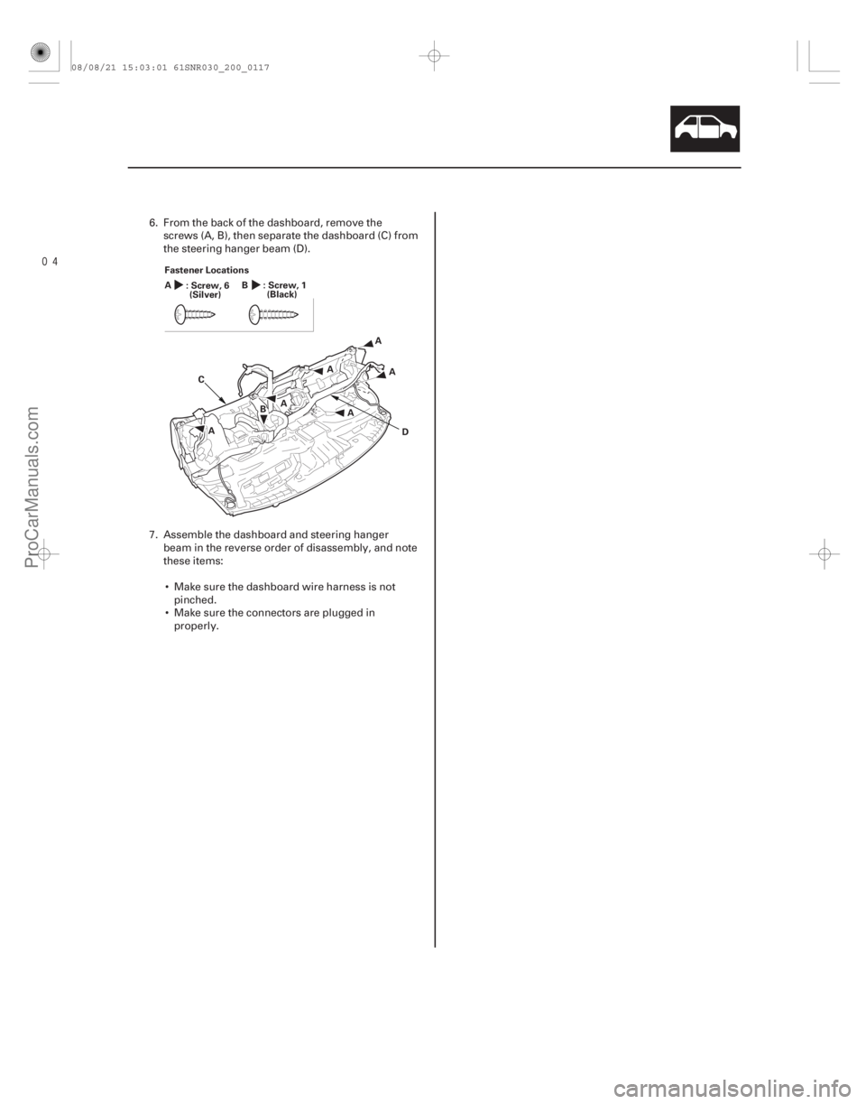
Fastener Locations
:Screw,6
A
:Screw,1
B
(Silver) (Black)
6. From the back of the dashboard, remove the
screws (A, B), then separate the dashboard (C) from
the steering hanger beam (D).
7. Assemble the dashboard and steering hanger beam in the reverse order of disassembly, and note
these items:
Make sure the dashboard wire harness is not pinched.
Make sure the connectors are plugged in properly.
08/08/21 15:03:01 61SNR030_200_0117
ProCarManuals.com
DYNOMITE -2009-
Page 1873 of 2893
���
�����(�#�'���������������
����������������� �����)���� ���
�(�#�'���������������
�������������
��� �����)����
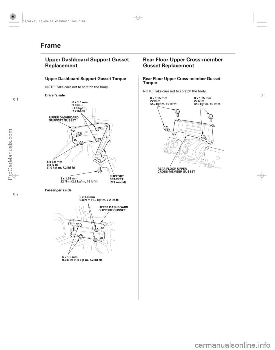
Upper Dashboard Support Gusset Torque Rear Floor Upper Cross-member Gusset Torque
Driver’s side
Passenger’s side
20-18620-186Frame
Upper Dashboard Support Gusset
Replacement
Rear Floor Upper Cross-member
Gusset Replacement
8x1.25mm
22 N·m (2.2 kgf·m, 16 lbf·ft)6x1.0mm
9.8 N·m
(1.0 kgf·m,
7.2 lbf·ft)
6x1.0mm
9.8 N·m
(1.0 kgf·m, 7.2 lbf·ft) UPPER DASHBOARD
SUPPORT GUSSET
SUPPORT
BRACKET
(MT model)
6x1.0mm
9.8 N·m (1.0 kgf·m, 7.2 lbf·ft) UPPER DASHBOARD
SUPPORT GUSSET
6x1.0mm
9.8 N·m (1.0 kgf·m, 7.2 lbf·ft) 8x1.25mm
22 N·m
(2.2 kgf·m, 16 lbf·ft)
8x1.25mm
22 N·m
(2.2 kgf·m, 16 lbf·ft)
REAR FLOOR UPPER
CROSS-MEMBER GUSSET
NOTE: Take care not to scratch the body. NOTE: Take care not to scratch the body.
08/08/21 15:05:36 61SNR030_200_0188
ProCarManuals.com
DYNOMITE -2009-
Page 1888 of 2893
���
�(�#�'�����������
�����������
�����
�
�������)�
��
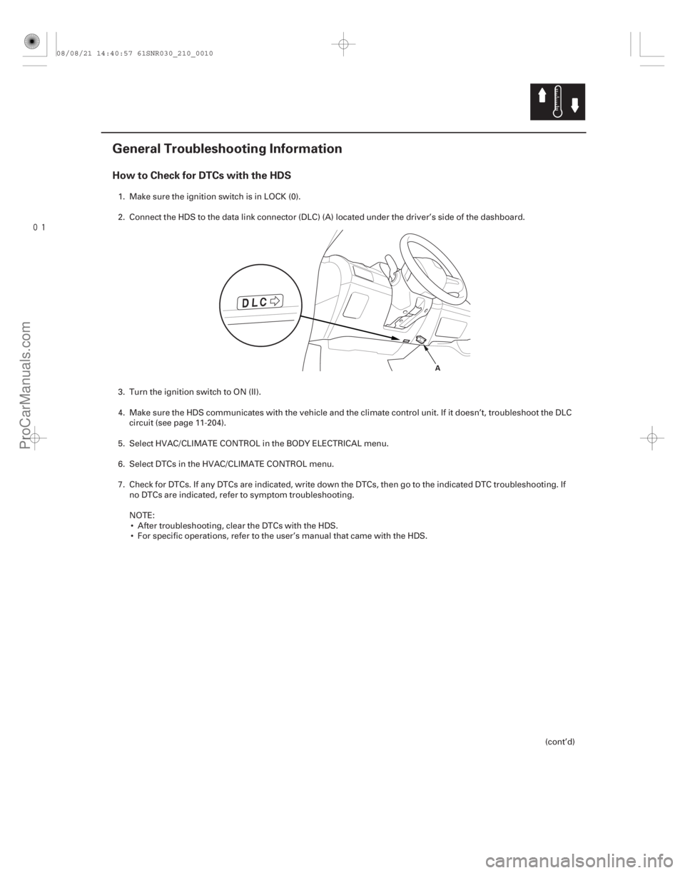
How to Check for DTCs with the HDS
21-9
General Troubleshooting Information
A
1. Make sure the ignition switch is in LOCK (0).
2. Connect the HDS to the data link connector (DLC) (A) located under the driver’s side of the dashboard.
3. Turn the ignition switch to ON (II).
4. Make sure the HDS communicates with the vehicle and the climate control unit. If it doesn’t, troubleshoot the DLCcircuit (see page 11-204).
5. Select HVAC/CLIMATE CONTROL in the BODY ELECTRICAL menu.
6. Select DTCs in the HVAC/CLIMATE CONTROL menu.
7. Check for DTCs. If any DTCs are indicated, write down the DTCs, then go to the indicated DTC troubleshooting. If no DTCs are indicated, refer to symptom troubleshooting.
NOTE: After troubleshooting, clear the DTCs with the HDS.
For specific operations, refer to the user’s manual that came with the HDS.
(cont’d)
08/08/21 14:40:57 61SNR030_210_0010
ProCarManuals.com
DYNOMITE -2009-
Page 1947 of 2893
���� ���
�(�#������������
�������������������
� �����)����
�µ
21-6721-67
In-car Temperature Sensor Test In-car Temperature Sensor Replacement
IN-CA")
���
�(�#�'�����������
�������������������
�������)���� ���
�(�#�'�����������
�������������������
� �����)����
�µ
21-6721-67
In-car Temperature Sensor Test In-car Temperature Sensor Replacement
IN-CAR TEMPERATURE SENSOR
10
14 0
32 10
5020
68 30
86
40 °C
104 °F
TEMPERATURE
RESISTANCE
(k )
12
11
10
98
7
6
5
4 3
2
1 A
B
1. Remove the in-car temperature sensor (see page21-67).
2. Test the in-car temperature sensor while holding it in front of the dashboard center vent.
Measure the resistance with the system set to Max Cool.
Measure the resistance with the system set to Max Hot.
3. Compare the resistance reading between terminals No. 1 and No. 2 of the in-car temperature sensor
with the specifications shown in the graph; the
resistance should be within the specifications.
4. If the resistance is not as specified, replace the in-car temperature sensor (see page 21-67). 1. Remove the center panel:
’06-08 models with navigation (see page 23-155)
’06-08 models without navigation (see page23-80)
’09 model with navigation (see page 23-355)
’09 model without navigation (see page 23-256)
2. Remove the self-tapping screw and the in-car temperature sensor (A) from the center panel (B).
3. Install the sensor in the reverse order of removal. Be sure to connect the air hose securely.
08/08/21 14:43:34 61SNR030_210_0068
ProCarManuals.com
DYNOMITE -2009-
Page 1949 of 2893
���� ���
�(�#������������
�������������������
� �����)����
21-6921-69
Sunlight Sensor Test Sunlight Sensor Replacement
REDPUR
A
A
B")
�´
�µ
�µ
�µ
���
�(�#�'�����������
�������������������
�������)���� ���
�(�#�'�����������
�������������������
� �����)����
21-6921-69
Sunlight Sensor Test Sunlight Sensor Replacement
REDPUR
A
A
B
1. Remove the sunlight sensor (A) from thedashboard (see page 21-69).
2. Turn the ignition switch to ON (II). Measure the voltage between the terminals with the ( ) probe
on terminal No. 2 and the ( ) probe on terminal
No. 1 with the connector connected.
NOTE: The voltage readings will not change under
the light of a flashlight or a fluorescent lamp.
Voltage should be: 3.6 3.7 V or more with the sensor out of direct sunlight.
3.3 3.5 V or less with the sensor in direct sunlight.
3. If the voltage is not as specified, replace the sunlight sensor (see page 21-69). 1. Remove the gauge control module (SPEEDO)
(see page 22-277).
2. Remove the sunlight sensor (A) from the dashboard with a flat-tip screwdriver, then
disconnect the connector (B). Be careful not to
damage the sensor and the dashboard.
3. Install the sensor in the reverse order of removal.
08/08/21 14:43:35 61SNR030_210_0070
ProCarManuals.com
DYNOMITE -2009-
Page 1951 of 2893
����
21-71
Power Transistor Test
POWER TRANSISTOR (To 12 V Power source on vehicle)JUMPER WIRE
A
1. Remove the passenger’s dashboard undercover")
���
����
�(�#�'���������������
�
�����
�������
�������)����
21-71
Power Transistor Test
POWER TRANSISTOR (To 12 V Power source on vehicle)JUMPER WIRE
A
1. Remove the passenger’s dashboard undercover
(see page 20-104).
2. Disconnect the 4P connector from the power transistor.
3. Measure the resistance between terminals No. 3 and No. 4 of the power transistor. It should be
about 1.5 k .
If the resistance is within the specifications, go to step 4.
If the resistance is not within the specifications, replace the power transistor.
NOTE: Also check the blower motor. Power
transistor failure can be caused by a defective
blower motor. 4. Carefully release the lock tab on terminal No. 1
(YEL) (A) in the 4P connector, then remove the
terminal and insulate it from body ground.
5. Reconnect the 4P connector to the power transistor.
6. Make sure the YEL wire is completely isolated, then supply 12 V to cavity No. 1 with a jumper wire.
7. Turn the ignition switch to ON (II), and check that the blower motor runs.
If the blower motor does not run, replace the power transistor.
NOTE: A faulty blower motor can cause the
power transistor to fail. If the power transistor is
replaced, also check the blower motor for
binding, and replace it if necessary.
If the blower motor runs, the power transistor is OK.
08/08/21 14:43:36 61SNR030_210_0072
ProCarManuals.com
DYNOMITE -2009-