Page 104 of 2893
����
���
����
�
��
5-5
A
B
A
B
15. Disconnect the evaporative emission (EVAP)
canister hose (A) and the brake booster vacuum
hose (B).
16. Remove the quick-connect fitting cover (A), then disconnect the fuel feed hose (B) (see page 11-329).
17. M/T model: Remove the shift cables. Do not bend the cables excessively (see step 7 on page 13-8).
18. M/T model: Remove the clutch slave cylinder, and the clutch line bracket mounting bolt (see step 5 on
page 13-7). 19. M/T model: Remove the air cleaner bracket.
20. Remove the drive belt (see page 4-31).
21. Remove the idler pulley base (see step 2 on page
4-32).
22. Wait until the engine is cool, then carefully remove the radiator cap.
23. Raise the vehicle on the lift.
24. Remove the front wheels.
25. Remove the splash shield.
26. Loosen the drain plug in the radiator, and drain the engine coolant (see page 10-8).
(cont’d)
08/08/21 14:20:23 61SNR030_050_0005
ProCarManuals.com
DYNOMITE -2009-
Page 105 of 2893

C
B
D
A B
C
A
D
D A
B
C
27. Drain the engine oil (see page 8-10).
28. Drain the transmission fluid: Manual transmission (see step 3 on page")
�
�
����
�
��
5-6Engine Assembly
Engine Removal (cont’d)
C
B
D
A B
C
A
D
D A
B
C
27. Drain the engine oil (see page 8-10).
28. Drain the transmission fluid: Manual transmission (see step 3 on page 13-5)
Automatic transmission (see step 3 on page14-232)
29. Disconnect the air fuel ratio (A/F) sensor connector (A).
30. Remove the grommet (B), then disconnect the secondary heated oxygen sensor (secondary
HO2S) connector (C).
31. Remove the three way catalytic converter (TWC) (D).
32. A/T model: Remove the shift cable. Do not bend the cables excessively (see step 39 on page 14-239).
33. Separate the stabilizer links (see page 18-25).
34. Separate the knuckles from the lower arms (see step 6 on page 18-21).
35. Remove the driveshafts (see page 16-4). Coat all precision-finished surfaces with new engine oil. Tie
plastic bags over the driveshaft ends. 36. Remove the steering gearbox bracket (A).
37. Remove the steering gearbox mounting bolt (B),
the stiffener mounting bolt (C), and the stiffener (D).
38. Remove the steering gearbox mounting bolt (A), the stiffener mounting bolt (B), and the stiffener (C).
39. Remove the harness clamp (D) from the subframe.
08/08/21 14:20:24 61SNR030_050_0006
ProCarManuals.com
DYNOMITE -2009-
Page 182 of 2893
����
6-386-38 Cylinder Head
Cylinder Head Cover Installation
(cont’d)
Cylinder Head Removal
B
C
A
6x1.0mm
10 N·m
(1.0 kgf·m, 7.2 lbf�")
����
���� ���
�(�#�'�����������
��������������������� �����)����
6-386-38 Cylinder Head
Cylinder Head Cover Installation
(cont’d)
Cylinder Head Removal
B
C
A
6x1.0mm
10 N·m
(1.0 kgf·m, 7.2 lbf·ft)
6x1.0mm
12 N·m
(1.2 kgf·m, 8.7 lbf·ft) A
B
8. Install two bolts (A) securing the evaporativeemission (EVAP) canister purge valve bracket.
9. Connect the breather hose (B), and install the dipstick (C).
10. Connect the evaporative emission (EVAP) canister purge valve connector.
11. Install the four ignition coils (see page 4-21).
12. Install the engine cover. NOTE:
Use fender covers to avoid damaging the painted surfaces.
To avoid damaging the wire and terminals, unplug the wiring connectors carefully while holding the
connector portion.
Connect the Honda Diagnostic System (HDS) to the data link connector (DLC) (see step 2 on page 11-3),
and monitor the engine coolant temperature (ECT)
sensor 1. To avoid damaging the cylinder head, wait
until the engine coolant temperature drops below
38 °C (100 °F) before loosening the cylinder head
bolts.
Mark all wiring and hoses to avoid misconnection. Also, be sure that they do not contact other wiring or
hoses, or interfere with other parts.
1. Relieve the fuel pressure (see page 11-322).
2. Drain the engine coolant (see page 10-8).
3. Remove the air cleaner assembly (see page 11-345).
4. Remove the drive belt (see page 4-31).
5. Remove the intake manifold: K20Z2 engine (see page 9-3)
K20Z3 engine (see page 9-7)
6. Remove the exhaust manifold (see page 9-11).
7. Disconnect the evaporative emission (EVAP) canister hose (A) and the brake booster vacuum
hose (B).
08/08/21 14:27:27 61SNR030_060_0038
ProCarManuals.com
DYNOMITE -2009-
Page 183 of 2893
����
6-386-38 Cylinder Head
Cylinder Head Cover Installation
(cont’d)
Cylinder Head Removal
B
C
A
6x1.0mm
10 N·m
(1.0 kgf·m, 7.2 lbf�")
����
���� ���
�(�#�'�����������
��������������������� �����)����
6-386-38 Cylinder Head
Cylinder Head Cover Installation
(cont’d)
Cylinder Head Removal
B
C
A
6x1.0mm
10 N·m
(1.0 kgf·m, 7.2 lbf·ft)
6x1.0mm
12 N·m
(1.2 kgf·m, 8.7 lbf·ft) A
B
8. Install two bolts (A) securing the evaporativeemission (EVAP) canister purge valve bracket.
9. Connect the breather hose (B), and install the dipstick (C).
10. Connect the evaporative emission (EVAP) canister purge valve connector.
11. Install the four ignition coils (see page 4-21).
12. Install the engine cover. NOTE:
Use fender covers to avoid damaging the painted surfaces.
To avoid damaging the wire and terminals, unplug the wiring connectors carefully while holding the
connector portion.
Connect the Honda Diagnostic System (HDS) to the data link connector (DLC) (see step 2 on page 11-3),
and monitor the engine coolant temperature (ECT)
sensor 1. To avoid damaging the cylinder head, wait
until the engine coolant temperature drops below
38 °C (100 °F) before loosening the cylinder head
bolts.
Mark all wiring and hoses to avoid misconnection. Also, be sure that they do not contact other wiring or
hoses, or interfere with other parts.
1. Relieve the fuel pressure (see page 11-322).
2. Drain the engine coolant (see page 10-8).
3. Remove the air cleaner assembly (see page 11-345).
4. Remove the drive belt (see page 4-31).
5. Remove the intake manifold: K20Z2 engine (see page 9-3)
K20Z3 engine (see page 9-7)
6. Remove the exhaust manifold (see page 9-11).
7. Disconnect the evaporative emission (EVAP) canister hose (A) and the brake booster vacuum
hose (B).
08/08/21 14:27:27 61SNR030_060_0038
ProCarManuals.com
DYNOMITE -2009-
Page 225 of 2893
����
7-11
Oil Pan Removal
1. If the engine is already out of the vehicle, go to step 18.
2. Raise the vehicle on the lift.
3. Drain the engine oi")
���
����
�(�#�'�����������
�������������������
� �����)����
7-11
Oil Pan Removal
1. If the engine is already out of the vehicle, go to step 18.
2. Raise the vehicle on the lift.
3. Drain the engine oil (see page 8-10).
4. Remove the front wheels.
5. Remove the splash shield (see step 25 on page 5-5).
6. Separate the stabilizer links (see page 18-25).
7. Separate the knuckles from the lower arms (see step 6 on page 18-21).
8. Remove the steering gearbox bracket. Remove the steering gearbox mounting bolt, the stiffener
mounting bolt, and the stiffener (see step 36 on
page 5-6).
9. Remove the steering gearbox mounting bolt, the stiffener mounting bolt, and the stiffener. Remove
the harness clamp from the front subframe (see
step 38 on page 5-6).
10. A/T model: Remove the bolt securing the automatic transmission fluid (ATF) filter.
11. Install the front leg assembly, the hook, and the wing nut to an A and Reds engine support hanger
(AAR-T1256) onto the 2006 Civic engine hanger
(VSB02C000025). Carefully position the engine
hanger on the vehicle, and attach the hook to the
slotted hole in the support eyelet. Tighten the wing
nut by hand to lift and support the engine/
transmission (see step 47 on page 5-8). 12. Remove the lower torque rod (see step 49 on page
5-8).
13. M/T model: Remove the front mount mounting bolt (see step 50 on page 5-9).
14. Make the appropriate reference line at both sides of the front subframe that line up with the edges on
the body (see step 51 on page 5-9).
15. Loosen the mid-stiffener mounting bolts on both sides(seestep52onpage5-9).
16. Attach the front subframe adapter (VSB02C000016) to the front subframe, and hang the belt of the front
subframe adapter over the front of the subframe.
Secure the belt with its stop, then tighten the wing
nut (see step 53 on page 5-9).
17. Remove the front subframe (see step 55 on page 5-10).
18. Remove the lower torque rod bracket.
(cont’d)
08/08/21 14:32:34 61SNR030_070_0011
ProCarManuals.com
DYNOMITE -2009-
Page 253 of 2893
����
�(�#�'���������������������������������������)���� K20Z2 engine
8-3
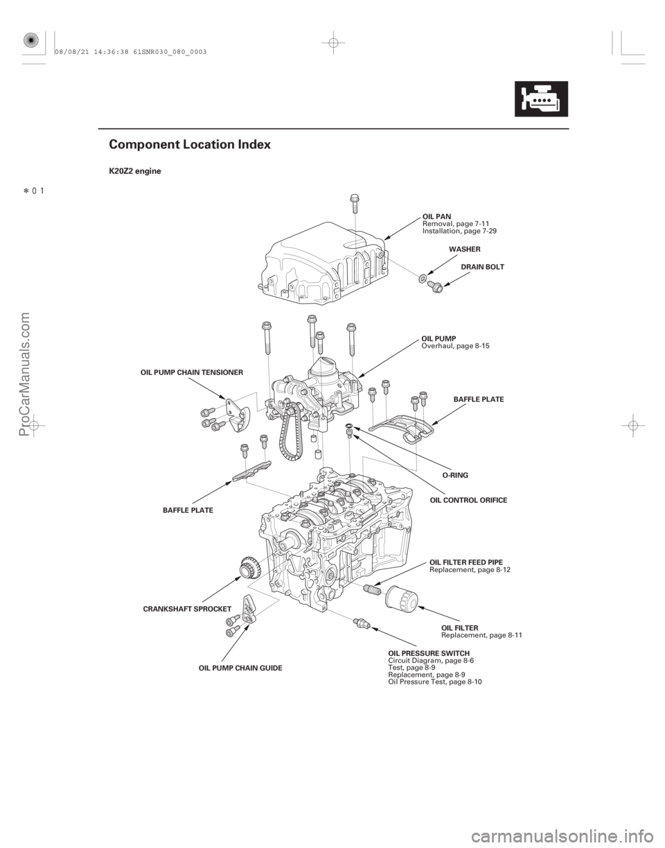
Component Location Index
OIL PRESSURE SWITCHOIL FILTER
OIL PUMP
DRAIN BOLT
O-RING
OIL PAN
BAFFLE PLATE
OIL CONTROL ORIFICE
OIL PUMP CHAIN GUIDE
CRANKSHAFT SPROCKET
OIL PUMP CHAIN TENSIONER
BAFFLE PLATE OIL FILTER FEED PIPEWASHER
Circuit Diagram, page 8-6
Test, page 8-9
Replacement, page 8-9
Oil Pressure Test, page 8-10 Replacement, page 8-11
Overhaul, page 8-15
Removal, page 7-11
Installation, page 7-29
Replacement, page 8-12
08/08/21 14:36:38 61SNR030_080_0003
ProCarManuals.com
DYNOMITE -2009-
Page 254 of 2893
����
�(�#�'���������������������������������������)���
K20Z3 engine
8-4Engine Lubrication
Component Location Index (cont’d)
OIL PRESSURE SWITCH
OIL FILTER
OIL PUMP
DRAIN BOLT
O-RING OIL PAN
BAFFLE PLATE
OIL CONTROL ORIFICE
OIL PUMP CHAIN GUIDE
CRANKSHAFT SPROCKET OIL PUMP CHAIN TENSIONER
BAFFLE PLATE
OIL COOLERWASHER
OIL COOLER CENTER BOLT OIL JETS
Circuit Diagram, page 8-6
Test, page 8-9
Replacement, page 8-9
Oil Pressure Test, page 8-10 Replacement, page 8-11
Overhaul, page 8-15
Removal, page 7-11
Installation, page 7-29
Replacement, page 8-13 Inspection, page 8-14
08/08/21 14:36:41 61SNR030_080_0004
ProCarManuals.com
DYNOMITE -2009-
Page 255 of 2893
���
Symptom Diagnostic procedure Also check for
8-5
Symptom Troubleshooting Index
Excessive engine oil
consumption
1.
2.
3.
4.
5.Verify that the engine oi")
�(�#�'���������������������������������������)���
Symptom Diagnostic procedure Also check for
8-5
Symptom Troubleshooting Index
Excessive engine oil
consumption
1.
2.
3.
4.
5.Verify that the engine oil filler cap, the oil drain
bolt, and the oil filter are tight.
Check for oil leaks.
Check for worn valve guide(s) (see page 6-55) or
worn valve stem seal(s) (see page 6-54).
Check for damaged or worn piston ring(s)
(see page 7-21).
Check for damaged or worn engine internal parts
(cylinder wall, pistons, etc.) (see page 7-16).
Low oil pressure indicator does
not come on with the ignition
switch in ON (II) 1.
2.Do the low oil pressure indicator circuit
troubleshooting (Open) (see page 8-7).
Test the oil pressure switch (see page 8-9). An open in the wire
between the engine
control module (ECM)/
powertrain control
module (PCM) and the
oil pressure switch
Low oil pressure indicator stays
on 1.
2.
3.
4.
5.
6.
7.
8.Check the engine oil level.
Do the low oil pressure indicator circuit
troubleshooting (Short) (see page 8-8).
Test the oil pressure switch (see page 8-9).
Check the engine oil pressure (see page 8-10).
Check the oil filter for clogging.
Check the oil screen for clogging.
Check the relief valve (see page 8-15).
Testtheoilpump(seepage8-17). A wire shorted to
ground between the
ECM/PCM and the oil
pressure switch
08/08/21 14:36:41 61SNR030_080_0005
ProCarManuals.com
DYNOMITE -2009-