Page 781 of 2893
�
�
�
���
��
����
13-10Manual Transmission
Transmission Removal (cont’d)
A
B
B
B
A
B A
B
C
DB
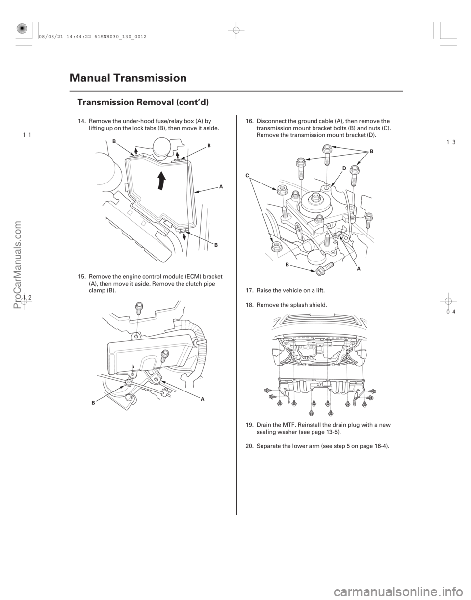
14. Remove the under-hood fuse/relay box (A) by
lifting up on the lock tabs (B), then move it aside.
15. Remove the engine control module (ECM) bracket (A), then move it aside. Remove the clutch pipe
clamp (B). 16. Disconnect the ground cable (A), then remove the
transmission mount bracket bolts (B) and nuts (C).
Remove the transmission mount bracket (D).
17. Raise the vehicle on a lift.
18. Remove the splash shield.
19. Drain the MTF. Reinstall the drain plug with a new sealing washer (see page 13-5).
20. Separate the lower arm (see step 5 on page 16-4).
08/08/21 14:44:22 61SNR030_130_0012
ProCarManuals.com
DYNOMITE -2009-
Page 796 of 2893

10 mm SEALING WASHER
FILLER PLUG
44 N·m (4.5 kgf·m, 33 lbf·ft)
40x56x8mmOIL")
�����
Exploded View - Transmission Housing
13-23
TRANSMISSION HOUSING32 mm SEALING CAP
34 N·m (3.5 kgf·m, 25 lbf·ft)
10 mm SEALING WASHER
FILLER PLUG
44 N·m (4.5 kgf·m, 33 lbf·ft)
40x56x8mmOILSEAL
10 mm FLANGE BOLT
44 N·m (4.5 kgf·m, 33 lbf·ft)
14 mm SEALING WASHER
TRANSMISSION HANGER A 8 mm FLANGE BOLT
27 N·m (2.8 kgf·m, 20 lbf·ft)
INTERLOCK BOLT
39 N·m (4.0 kgf·m, 29 lbf·ft)
OIL GUIDE PLATE M
72 mm SHIM
OIL GUTTER PLATE
DRAIN PLUG
39 N·m (4.0 kgf·m, 29 lbf·ft) 20 mm SEALING WASHER STEEL BALL SPRING
TRANSMISSION HANGER B DETENT BOLT
22 N·m (2.2 kgf·m, 16 lbf·ft)
12 mm SEALING WASHER
HARNESS BRACKET A
6 x 30 mm FLANGE BOLT
12 N·m (1.2 kgf·m, 9 lbf·ft) 8x14mmDOWELPIN
CHANGE LEVER ASSEMBLY TRANSMISSION HANGER
10 mm FLANGE BOLT
44 N·m (4.5 kgf·m, 33 lbf·ft)
PLAIN WASHER
6 x 20 mm FLANGE BOLT
12 N·m (1.2 kgf·m, 9 lbf·ft) 6 mm FLANGE BOLT
12 N·m (1.2 kgf·m, 9 lbf·ft) OUTPUT SHAFT (COUNTERSHAFT)
SPEED SENSOR
O-RING
80 mm SHIM
(cont’d)
Replace.
Replace.
Replace. Replace. Replace. Replace.
08/08/21 14:44:57 61SNR030_130_0025
ProCarManuals.com
DYNOMITE -2009-
Page 797 of 2893
��������� ����
�����
13-24 Manual Transmission
Transmission Disassembly (cont’d)
C
A
A
D E
B C
F
D
B
AB B
C
D
A
D
AB
D
C D
D
E
G
F
NOTE: Place the clutch housing on two pieces of wood
thick enough to keep the mainshaft from hitting the
workbench.
1. Remove the release fork and the replace bearing (see page 12-24).
2. Remove the detent bolts (A), the 12 mm sealing washers (B), the springs (C), the steel balls (D), and
the back-up light switch (E). Then remove the
transmission hanger (F).
3. Remove the 20 mm bolt (A) and the 20 mm sealing washer (B). 4. Remove the interlock bolt (B), the change lever
assembly(C),the8x14mmdowelpins(D),and
harness bracket A.
5. Remove the drain plug (A), the filler plug (B), the 10 mm flange bolt (C), and the sealing washers (D).
6. Remove the output shaft (countershaft) speed sensor (E) with the O-ring (F) and the plain washer
(G).
08/08/21 14:44:58 61SNR030_130_0026
ProCarManuals.com
DYNOMITE -2009-
Page 835 of 2893

13-59
Liquid gasket
D
39 N·m
(4.0 kgf·m,
29 lbf·ft)
C
B
A
B
6x1.0mm
12 N·m (1.2 kgf·m, 8.7 lbf·ft)
B
44 N�")
������
�� �����
�����
Specified Torque:
8x1.25mm
27 N·m (2.8 kgf·m, 20 lbf·ft)
13-59
Liquid gasket
D
39 N·m
(4.0 kgf·m,
29 lbf·ft)
C
B
A
B
6x1.0mm
12 N·m (1.2 kgf·m, 8.7 lbf·ft)
B
44 N·m
(4.5 kgf·m, 33 lbf·ft)
G
H
F
A
39 N·m
(4.0 kgf·m,
33 lbf·ft)
6x1.0mm
12 N·m (1.2 kgf·m, 8.7 lbf·ft) D
E
C
C
15. Tighten the 8 mm flange bolts in a crisscross pattern in several steps.
16. Clean any dirt or oil from the mating surface of the change lever assembly and the transmission
housing. Apply liquid gasket, P/N 08718-0001
evenly to the mating surface of the change lever
assembly and the transmission housing. Install the
component within 5 minutes of applying the liquid
gasket.
NOTE: If you apply liquid gasket P/N 08718-0012, the component must be installed within 4 minutes.
If too much time has passed after applying the liquid gasket, remove the old liquid gasket and
residue, then reapply new liquid gasket. 17. Installthe8x14mmdowelpins(B)andthechange
lever assembly (C) with harness bracket A.
18. Apply liquid gasket, P/N 08718-0001, evenly to the threads of the inter lock bolt (D). Install the
component within 5 minutes of applying the liquid
gasket.
NOTE: If you apply liquid gasket P/N 08718-0012, the component must be installed within 4 minutes.
If too much time has passed after applying the liquid gasket, remove the old liquid gasket and
residue, then reapply new liquid gasket.
19. Install the drain plug (A) and the 10 mm flange bolt (B) with new washers (C). Install the filler plug (D)
finger-tight with new sealing washer (E).
20. Apply MTF to a new O-ring (F). Then install the output shaft (countershaft) speed sensor (G) with
the O-ring and the plain washer (H).
(cont’d)
Replace.Replace.
Replace.
Replace.
08/08/21 14:46:29 61SNR030_130_0061
ProCarManuals.com
DYNOMITE -2009-
Page 856 of 2893
�
�
�
���
��
�
��
13-87
A
B
B
B
A
B A
B
C D
B
14. Remove the under-hood fuse/relay box (A) by lifting up on the lock tabs (B), then move it aside.
15. Remove the engine control module (ECM) bracket (A), then move it aside. Remove the clutch line
clamp (B). 16. Disconnect the ground cable (A), then remove the
transmission mount bracket bolts (B) and nuts (C).
Remove the transmission mount bracket (D).
17. Raise the vehicle on a lift.
18. Remove the splash shield.
19. Drain the MTF. Reinstall the drain plug with a new sealing washer (see page 13-82).
20. Separate the lower arm (see step 5 on page 16-4).
(cont’d)
08/08/21 14:47:22 61SNR030_130_0089
ProCarManuals.com
DYNOMITE -2009-
Page 869 of 2893

TRANSMISSION HOUSING
32 mm SEALING CAP
34 N·m (3.5 kgf·m, 25 lbf·ft)
10 mm SEALING WASHER")
�����
Exploded View - Transmission Housing
13-100Manual Transmission
Transmission Disassembly (cont’d)
TRANSMISSION HOUSING
32 mm SEALING CAP
34 N·m (3.5 kgf·m, 25 lbf·ft)
10 mm SEALING WASHER
FILLER PLUG
44 N·m (4.5 kgf·m, 33 lbf·ft)
40x56x8mmOILSEAL
10 mm FLANGE BOLT
44 N·m (4.5 kgf·m, 33 lbf·ft)
14 mm SEALING WASHER
TRANSMISSION HANGER A 8 mm FLANGE BOLT
27 N·m (2.8 kgf·m, 20 lbf·ft)
INTERLOCK BOLT
39 N·m (4.0 kgf·m, 29 lbf·ft)
OIL GUIDE PLATE M
72 mm SHIM
OIL GUTTER PLATE
DRAIN PLUG
39 N·m (4.0 kgf·m, 29 lbf·ft) 20 mm SEALING WASHER STEEL BALL SPRING
TRANSMISSION HANGER B DETENT BOLT
22 N·m (2.2 kgf·m, 16 lbf·ft)
12 mm SEALING WASHER
HARNESS BRACKET A
6 x 30 mm FLANGE BOLT
12 N·m (1.2 kgf·m, 9 lbf·ft) 8x14mmDOWELPIN
CHANGE LEVER ASSEMBLY TRANSMISSION HANGER
10 mm FLANGE BOLT
44 N·m (4.5 kgf·m, 33 lbf·ft)
6 x 20 mm FLANGE BOLT
12 N·m (1.2 kgf·m, 9 lbf·ft) 6 mm FLANGE BOLT
12 N·m (1.2 kgf·m, 9 lbf·ft) OUTPUT SHAFT (COUNTERSHAFT)
SPEED SENSOR
O-RING
80 mm SHIM Replace.
Replace.
Replace. Replace. Replace.Replace.
08/08/21 14:47:54 61SNR030_130_0102
ProCarManuals.com
DYNOMITE -2009-
Page 870 of 2893
��������� ����
�����
13-101
C
A
A
D E
B C
F
D
B
AB A
D
D
C B
AB
D
C D
D
E
F
NOTE: Place the clutch housing on two pieces of wood
thick enough to keep the mainshaft from hitting the
workbench.
1. Remove the release fork and the release bearing (see page 12-24).
2. Remove the detent bolts (A), the 12 mm sealing washers (B) the springs (C), the steel balls (D), and
the back-up light switch (E). Then remove the
transmission hanger (F).
3. Remove the 20 mm bolt (A) and the 20 mm sealing washer (B). 4. Remove the interlock bolt (B), the change lever
assembly(C),the8x14mmdowelpins(D),and
harness bracket A.
5. Remove the drain plug (A), the filler plug (B), the 10 mm flange bolt (C), and the sealing washers (D).
6. Remove the output shaft (countershaft) speed sensor (E) with the O-ring (F).
(cont’d)
08/08/21 14:47:55 61SNR030_130_0103
ProCarManuals.com
DYNOMITE -2009-
Page 906 of 2893

G
F A
39 N·m
(4.0 kgf·m,
29 lbf·ft)
6x1.0mm
12 N·m (1.2 kgf·m, 8.7 lbf·ft) D
E
C
C
B E
A
C
22 N·m
(2.2 kgf·m,
16 lbf·ft) D
F
29 N")
�����
���������
13-137
B
44 N·m
(4.5 kgf·m, 33 lbf·ft)
G
F A
39 N·m
(4.0 kgf·m,
29 lbf·ft)
6x1.0mm
12 N·m (1.2 kgf·m, 8.7 lbf·ft) D
E
C
C
B E
A
C
22 N·m
(2.2 kgf·m,
16 lbf·ft) D
F
29 N·m (3.0 kgf·m, 22 lbf·ft)
10x1.25mm
44 N·m
(4.5 kgf·m,
33 lbf·ft) A
44 N·m
(4.5 kgf·m, 33 lbf·ft)
B
18. Install the drain plug (A) and the 10 mm flange bolt
(B) with new washers (C). Install the filler plug (D)
finger-tight with new sealing washer (E).
19. Apply MTF to a new O-ring (F). Then install the output shaft (countershaft) speed sensor (G) with
the O-ring.
20. Install the steel balls (A), the springs (B), and the detent bolts (C) with new washers (D).
21. Install the transmission hanger (E). 22. Apply liquid gasket, P/N 08718-0001 evenly to the
threads of the back-up light switch (F), and install it
on the transmission housing. Install the component
within 5 minutes of applying the liquid gasket.
NOTE: If you apply liquid gasket P/N 08718-0012, the component must be installed within 4 minutes.
If too much time has passed after applying the liquid gasket, remove the old liquid gasket and
residue, then reapply new liquid gasket.
23. Install the 20 mm bolt (A) with new 20 mm sealing washer (B).
Replace. Replace.
Replace.
Replace.
Replace. Replace.
08/08/21 14:48:45 61SNR030_130_0139
ProCarManuals.com
DYNOMITE -2009-