Page 1400 of 2893
���
��������
�
17-77
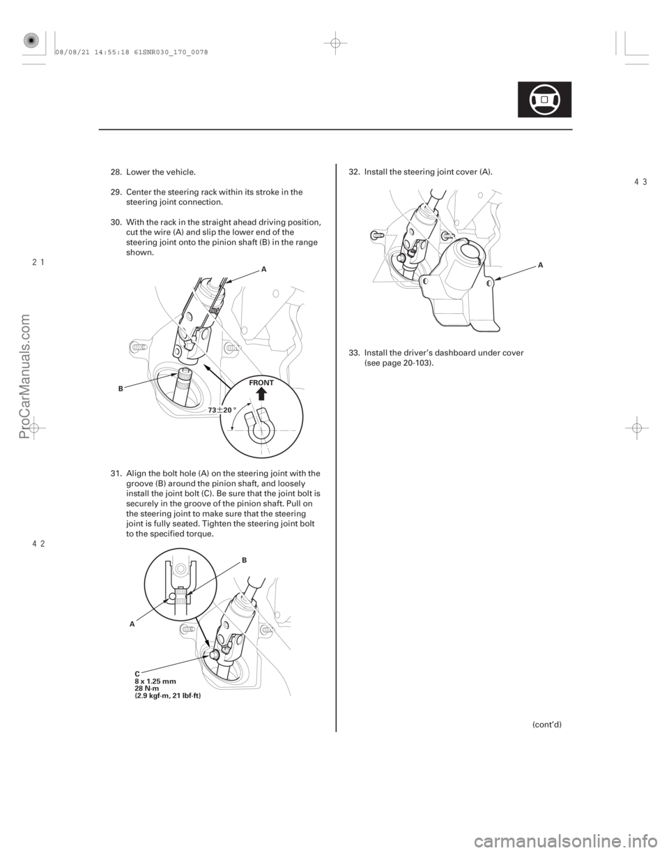
73 20 °
B A
FRONT
C
8x1.25mm
28 N·m
(2.9 kgf·m, 21 lbf·ft)
A
B A
28. Lower the vehicle.
29. Center the steering rack within its stroke in the
steering joint connection.
30. With the rack in the straight ahead driving position, cut the wire (A) and slip the lower end of the
steering joint onto the pinion shaft (B) in the range
shown.
31. Align the bolt hole (A) on the steering joint with the groove (B) around the pinion shaft, and loosely
install the joint bolt (C). Be sure that the joint bolt is
securely in the groove of the pinion shaft. Pull on
the steering joint to make sure that the steering
joint is fully seated. Tighten the steering joint bolt
to the specified torque. 32. Install the steering joint cover (A).
33. Install the driver’s dashboard under cover
(see page 20-103).
(cont’d)
08/08/21 14:55:18 61SNR030_170_0078
ProCarManuals.com
DYNOMITE -2009-
Page 1407 of 2893
����
17-84EPS Components
EPS Control Unit Removal/Installation
A
B
C D
F
E
6x1.0mm
9.8 N·m
(1.0 kgf·m,
7.2 lbf·ft)
1. Do the battery terminal disco")
���
�(�#�'�����������
���
�����������
���
� �����)����
17-84EPS Components
EPS Control Unit Removal/Installation
A
B
C D
F
E
6x1.0mm
9.8 N·m
(1.0 kgf·m,
7.2 lbf·ft)
1. Do the battery terminal disconnection procedure (see page 22-68).
2. Remove the passenger’s dashboard lower cover (see page 20-102).
3. Remove the passenger’s side kick panel (see page 20-66).
4. Disconnect EPS control unit connectors A (2P), connector B (2P), connector C (2P), and connector D
(28P).
5. Remove the nuts (E) from the EPS control unit (F).
6. Remove the EPS control unit. 7. Install the EPS control unit in the reverse order of
removal.
8. Do the battery terminal reconnection procedure (see page 22-68), and do these tasks:
Make sure the horn and turn signal switches work properly.
Make sure the steering wheel switches work properly.
If the EPS control unit is replaced, the EPS control unit must memorize the torque sensor neutral
position (see page 17-22).
9. After installation, start the engine, and let it idle. Turn the steering wheel from lock-to-lock several
times. Check that the EPS indicator does not come
on.
08/08/21 14:55:30 61SNR030_170_0085
ProCarManuals.com
DYNOMITE -2009-
Page 1463 of 2893
, connect the
HDS (Honda Diagnostic System) to the data link
connector (DLC) (A) located under the driv")
��������
How to Retrieve DTCs
How to Clear DTCs
18-51
A A
1. With the ignition switch in LOCK (0), connect the
HDS (Honda Diagnostic System) to the data link
connector (DLC) (A) located under the driver’s side
of the dashboard.
2. Turn the ignition switch to ON (II).
3. Make sure the HDS communicates with the vehicle and the TPMS control unit. If it doesn’t,
troubleshoot the DLC circuit (see page 11- 204).
4. Follow the prompts on the HDS to display the DTC(s) on the screen. After determining the DTC,
refer to the DTC troubleshooting.
NOTE: See the HDS Help menu for specific
instructions.
5. Turn the ignition switch to LOCK (0). 1. With the ignition switch in LOCK (0), connect the
HDS to the data link connector (DLC) (A) located
under the driver’s side of the dashboard.
2. Turn the ignition switch to ON (II).
3. Make sure the HDS communicates with the vehicle and the TPMS control unit. If it doesn’t,
troubleshoot the DLC circuit (see page 11-204).
4. Clear the DTC(s) by following the screen prompts on the HDS.
NOTE: See the HDS Help menu for specific
instructions.
5. Turn the ignition switch to LOCK (0).
08/08/21 14:58:22 61SNR030_180_0051
ProCarManuals.com
DYNOMITE -2009-
Page 1464 of 2893
����
Special Tools Required
18-52
TPMS
Memorizing the Tire Pressure Sensor ID
A
TPMS tool J-48714
TPMS tool J-48714
Bartech Wheel")
�Ì�Ï
���
����
����
�(�#�'���������������
�����
���������
�!�����)����
Special Tools Required
18-52
TPMS
Memorizing the Tire Pressure Sensor ID
A
TPMS tool J-48714
TPMS tool J-48714
Bartech Wheelrite Tech300 TPMS tool J-48714
Available through Honda Canada Inc. Technical Tools
Department; Fax 866-398-8665/
e-mail: ch_technicaltools ch.honda.com
All four tire pressure sensor IDs must be memorized to
the TPMS control unit whenever you do any of these
actions: Replace the TPMS control unit.
Replace the tire pressure sensor.
Substitute a known-good wheel with tire pressure sensor.
NOTE: To ensure the control unit memorizes the correct ID, the vehicle with the new sensor must be at least 3 m
(10 ft) away from other vehicles that have tire
pressure sensors.
When doing a tire rotation, memorizing the sensors in not needed.
1. With the ignition switch in LOCK (0), connect the HDS to the data link connector (DLC) (A) located
under the driver’s side of the dashboard.
2. Turn the ignition switch to ON (II).
3. Make sure the HDS communicates with the vehicle and the TPMS control unit. If it doesn’t,
troubleshoot the DLC circuit (see page 11- 204).
4. Select Sensor ID Learning from the mode menu on the HDS. 5. Turn on the TPMS tool by pressing the green select
button. Press the green select button until the
proper light sequence is illuminated as per the tool
user’s manual.
6. Hold the TPMS tool near one wheel, memorize the tire pressure sensor ID by following the screen
prompts on the HDS.
NOTE: If you turn the ignition switch to LOCK (0) before memorizing all four sensor IDs, the memorizing
ID is canceled.
See the HDS Help menu for specific instructions.
7. Repeat step 6 for each wheel until all four sensor IDs are memorized. When all four IDs are
memorized, the low tire pressure indicator blinks.
08/08/21 14:58:23 61SNR030_180_0052
ProCarManuals.com
DYNOMITE -2009-
Page 1465 of 2893
���� Special Tools Required
18-5318-53
Tire Pressure Sensor Location
A
8. Turn the ignition switch to LOCK (0).
9. Disconnect the HDS from the")
�Ì�Ï
���
�(�#�'���������������
�����
�����������"�����)���� Special Tools Required
18-5318-53
Tire Pressure Sensor Location
A
8. Turn the ignition switch to LOCK (0).
9. Disconnect the HDS from the DLC.
10. Test-drive the vehicle at 45 km/h (28 mph) or more for at least 1 minute.
11. Make sure the low tire pressure indicator does not blink.
12. Make sure the tires are inflated to the specified tire pressure listed on the doorjamb sticker.
13. Turn the ignition switch to LOCK (0). Bartech Wheelrite Tech300 TPMS tool J-48714
Available through Honda Canada Inc. Technical Tools
Department; Fax 866-398-8665/
e-mail: ch_technicaltools ch.honda.com
NOTE:
This procedure locates where the tire pressure sensors 1, 2, 3, 4 are mounted, when activated by the
TPMS sensor initializer tool.
Position the vehicle at least 3 m (10 ft) away from other vehicles that have tire pressure sensors.
1. With the ignition switch in LOCK (0), connect the HDS to the data link connector (DLC) (A) located
under the driver’s side of the dashboard.
2. Turn the ignition switch to ON (II).
3. Make sure the HDS communicates with the vehicle and the TPMS control unit. If it doesn’t,
troubleshoot the DLC circuit (see page 11-204).
4. Select Function Test from the mode menu, then select Sensor Position Check on the HDS.
(cont’d)
08/08/21 14:58:23 61SNR030_180_0053
ProCarManuals.com
DYNOMITE -2009-
Page 1466 of 2893
���� Special Tools Required
18-5318-53
Tire Pressure Sensor Location
A
8. Turn the ignition switch to LOCK (0).
9. Disconnect the HDS from the")
�Ì�Ï
���
�(�#�'���������������
�����
�����������"�����)���� Special Tools Required
18-5318-53
Tire Pressure Sensor Location
A
8. Turn the ignition switch to LOCK (0).
9. Disconnect the HDS from the DLC.
10. Test-drive the vehicle at 45 km/h (28 mph) or more for at least 1 minute.
11. Make sure the low tire pressure indicator does not blink.
12. Make sure the tires are inflated to the specified tire pressure listed on the doorjamb sticker.
13. Turn the ignition switch to LOCK (0). Bartech Wheelrite Tech300 TPMS tool J-48714
Available through Honda Canada Inc. Technical Tools
Department; Fax 866-398-8665/
e-mail: ch_technicaltools ch.honda.com
NOTE:
This procedure locates where the tire pressure sensors 1, 2, 3, 4 are mounted, when activated by the
TPMS sensor initializer tool.
Position the vehicle at least 3 m (10 ft) away from other vehicles that have tire pressure sensors.
1. With the ignition switch in LOCK (0), connect the HDS to the data link connector (DLC) (A) located
under the driver’s side of the dashboard.
2. Turn the ignition switch to ON (II).
3. Make sure the HDS communicates with the vehicle and the TPMS control unit. If it doesn’t,
troubleshoot the DLC circuit (see page 11-204).
4. Select Function Test from the mode menu, then select Sensor Position Check on the HDS.
(cont’d)
08/08/21 14:58:23 61SNR030_180_0053
ProCarManuals.com
DYNOMITE -2009-
Page 1488 of 2893
����
18-75
TPMS Control Unit Replacement
A
B
C
D
C B
6x1.0mm
9.8 N·m (1.0 kgf·m, 7.2 lbf·ft)
NOTE: Make sure the TPMS control unit mounting
brac")
����
�(�#�'���������������
�����
���������
� �����)����
18-75
TPMS Control Unit Replacement
A
B
C
D
C B
6x1.0mm
9.8 N·m (1.0 kgf·m, 7.2 lbf·ft)
NOTE: Make sure the TPMS control unit mounting
bracket is not bent or twisted as this may affect its
communication with the tire pressure sensors.
1. Turn the ignition switch to LOCK (0).
2. Remove the driver’s dashboard undercover (see page 20-103).
3. Disconnect the TPMS control unit connector (A).
4. Remove the TPMS control unit (B) from the bracket (C).
NOTE: To disconnect the TPMS control unit from its
bracket, insert a small flat-tipped screwdriver
between the TPMS control unit and the bracket
shown in (D) to release the hook, then slide out the
TPMS unit.
5. Replace the bracket if necessary. 6. Install the new TPMS control unit in the reverse
order of removal.
NOTE: Make sure the TPMS control unit is properly
installed. You will hear a click when the TPMS
control unit is securely mounted on the bracket.
7. Connect the HDS, and memorize the tire pressure sensor IDs using the TPMS sensor initializer tool
(see page 18-52).
08/08/21 14:59:01 61SNR030_180_0075
ProCarManuals.com
DYNOMITE -2009-
Page 1544 of 2893
How to Retrieve DTCs
How to Clear DTCs
19-51
A
1. If the system indicators stay on, connect the HDS to
the data link connector (DLC) (A) located under")
����
How to Use the HDS (Honda Diagnostic
System)How to Retrieve DTCs
How to Clear DTCs
19-51
A
1. If the system indicators stay on, connect the HDS to
the data link connector (DLC) (A) located under the
driver’s side of the dashboard.
2. Turn the ignition switch to ON (II).
3. Make sure the HDS communicates with the vehicle and the ABS modulator-control unit. If it doesn’t,
troubleshoot the DLC circuit (see page 11- 204).
4. Check the diagnostic trouble code (DTC) for all systems, troubleshoot the powertrain DTCs first
and note it. Then refer to the indicated DTC’s
troubleshooting, and do the appropriate
troubleshooting procedure.
NOTE: The HDS communication stops when the vehicle speed is at 50 km/h (31 mph) or more.
The HDS can read the DTC, the current data, and other system data.
For specific operations, refer to the Help menu that came with the HDS. 1. With the ignition switch in LOCK (0), connect the
HDS to the data link connector (DLC) under the
driver’s side of the dashboard.
2. Turn the ignition switch to ON (II).
3. Make sure the HDS communicates with the vehicle and the ABS modulator-control unit. If it doesn’t,
troubleshoot the DLC circuit (see page 11-204).
4. Follow the prompts on the HDS to display the DTC(s) on the screen. After determining the DTC,
refer to the DTC troubleshooting. Do the all
systems DTC check, and troubleshoot any
powertrain DTCs first.
5. Turn the ignition switch to LOCK (0).
1. With the ignition switch in LOCK (0), connect the HDS to the data link connector (DLC) under the
driver’s side of the dashboard.
2. Turn the ignition switch to ON (II).
3. Make sure the HDS communicates with the vehicle and the ABS modulator-control unit. If it doesn’t,
troubleshoot the DLC circuit (see page 11-204).
4. Clear the DTC(s) by following the screen prompts on the HDS.
5. Turn the ignition switch to LOCK (0).
08/08/21 15:02:15 61SNR030_190_0051
ProCarManuals.com
DYNOMITE -2009-