Page 1148 of 2893
����
���� ����
�(�#�'�������
���
�����������
�������
� �����)����
Automatic Transmission Fluid Capacity:
2.9 L (3.1 US qt) at change
6.5 L (6.9 US qt) at overhaul
14-232 Automatic Transmission
ATF Replacement
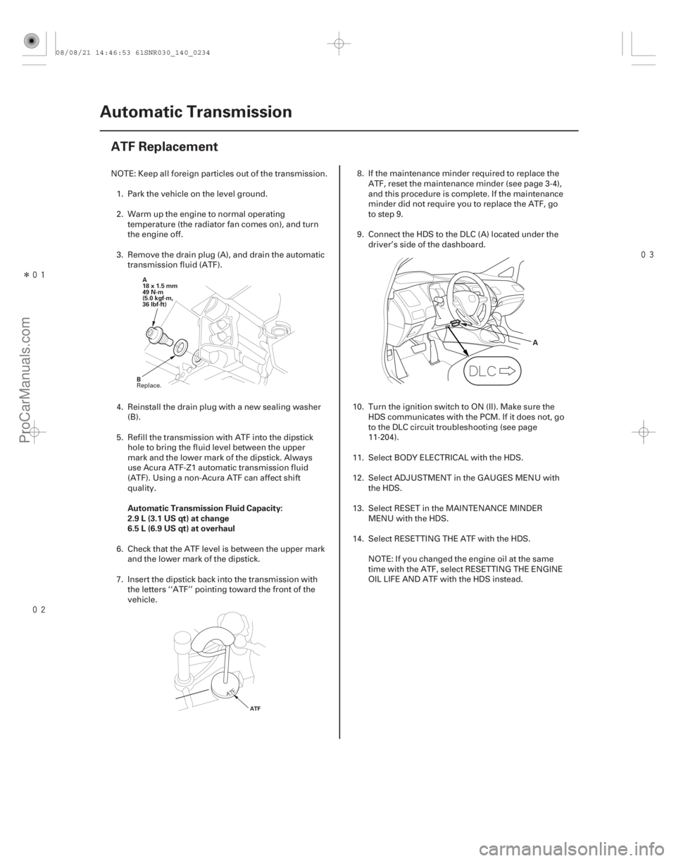
A
18 x 1.5 mm
49 N·m
(5.0 kgf·m,
36 lbf·ft)
B
ATF
A
NOTE: Keep all foreign particles out of the transmission. 1. Park the vehicle on the level ground.
2. Warm up the engine to normal operating temperature (the radiator fan comes on), and turn
the engine off.
3. Remove the drain plug (A), and drain the automatic transmission fluid (ATF).
4. Reinstall the drain plug with a new sealing washer (B).
5. Refill the transmission with ATF into the dipstick hole to bring the fluid level between the upper
mark and the lower mark of the dipstick. Always
use Acura ATF-Z1 automatic transmission fluid
(ATF). Using a non-Acura ATF can affect shift
quality.
6. Check that the ATF level is between the upper mark
and the lower mark of the dipstick.
7. Insert the dipstick back into the transmission with the letters ‘‘ATF’’ pointing toward the front of the
vehicle. 8. If the maintenance minder required to replace the
ATF, reset the maintenance minder (see page 3-4),
and this procedure is complete. If the maintenance
minder did not require you to replace the ATF, go
to step 9.
9. Connect the HDS to the DLC (A) located under the driver’s side of the dashboard.
10. Turn the ignition switch to ON (II). Make sure the HDS communicates with the PCM. If it does not, go
to the DLC circuit troubleshooting (see page
11-204).
11. Select BODY ELECTRICAL with the HDS.
12. Select ADJUSTMENT in the GAUGES MENU with the HDS.
13. Select RESET in the MAINTENANCE MINDER MENU with the HDS.
14. Select RESETTING THE ATF with the HDS.
NOTE: If you changed the engine oil at the same
time with the ATF, select RESETTING THE ENGINE
OIL LIFE AND ATF with the HDS instead.
Replace.
08/08/21 14:46:53 61SNR030_140_0234
ProCarManuals.com
DYNOMITE -2009-
Page 1197 of 2893
����
���
����
�(�#�'�������
���
�������������������
�������)�
��
�µ
�µ �µ
�µ
�µ
�µ
YES
NO
YES
NO
YES
NO
14-280A/T Interlock System
Shift Lock System Circuit Troubleshooting
A
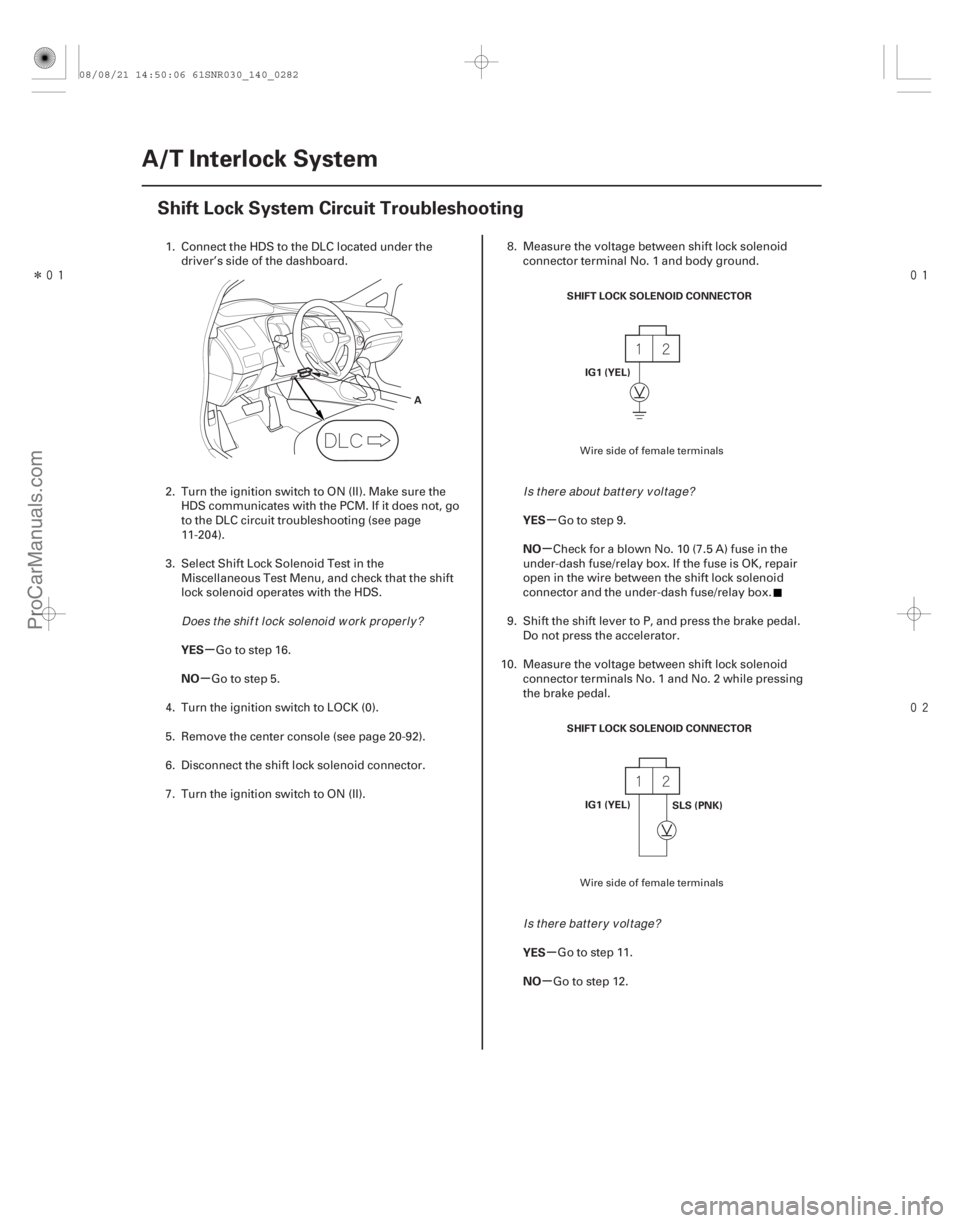
SHIFT LOCK SOLENOID CONNECTOR
IG1 (YEL)
SHIFT LOCK SOLENOID CONNECTOR IG1 (YEL) SLS (PNK)
1. Connect the HDS to the DLC located under the
driver’s side of the dashboard.
2. Turn the ignition switch to ON (II). Make sure the HDS communicates with the PCM. If it does not, go
to the DLC circuit troubleshooting (see page
11-204).
3. Select Shift Lock Solenoid Test in the Miscellaneous Test Menu, and check that the shift
lock solenoid operates with the HDS.
Go to step 16.
Go to step 5.
4. Turn the ignition switch to LOCK (0).
5. Remove the center console (see page 20-92).
6. Disconnect the shift lock solenoid connector.
7. Turn the ignition switch to ON (II). 8. Measure the voltage between shift lock solenoid
connector terminal No. 1 and body ground.
Go to step 9.
CheckforablownNo.10(7.5A)fuseinthe
under-dash fuse/relay box. If the fuse is OK, repair
open in the wire between the shift lock solenoid
connector and the under-dash fuse/relay box.
9. Shift the shift lever to P, and press the brake pedal. Do not press the accelerator.
10. Measure the voltage between shift lock solenoid connector terminals No. 1 and No. 2 while pressing
the brake pedal.
Go to step 11.
Go to step 12.
Wire side of female terminals
Wire side of female terminals
Does t he shi f t l ock sol enoi d w or k pr oper l y ? Is t her e about bat t er y v ol t age?
Is there battery voltage?
08/08/21 14:50:06 61SNR030_140_0282
ProCarManuals.com
DYNOMITE -2009-
Page 1205 of 2893
���
�(�#�'�������
���
���������������
���
�������)���� ���
�(�#�'�������
���
���������������
���
� �����)���
14-28714-287
Shift Lock Solenoid Test Shift Lock Solenoid Replacement
A
A
B
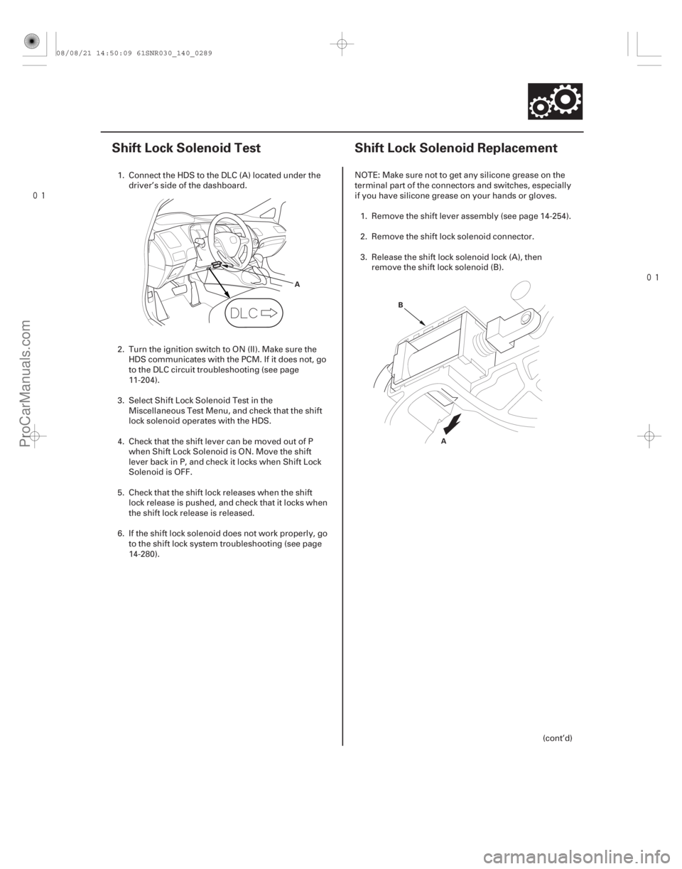
1. Connect the HDS to the DLC (A) located under the
driver’s side of the dashboard.
2. Turn the ignition switch to ON (II). Make sure the HDS communicates with the PCM. If it does not, go
to the DLC circuit troubleshooting (see page
11-204).
3. Select Shift Lock Solenoid Test in the Miscellaneous Test Menu, and check that the shift
lock solenoid operates with the HDS.
4. Check that the shift lever can be moved out of P when Shift Lock Solenoid is ON. Move the shift
lever back in P, and check it locks when Shift Lock
Solenoid is OFF.
5. Check that the shift lock releases when the shift lock release is pushed, and check that it locks when
the shift lock release is released.
6. If the shift lock solenoid does not work properly, go to the shift lock system troubleshooting (see page
14-280). NOTE: Make sure not to get any silicone grease on the
terminal part of the connectors and switches, especially
if you have silicone grease on your hands or gloves.
1. Remove the shift lever assembly (see page 14-254).
2. Remove the shift lock solenoid connector.
3. Release the shift lock solenoid lock (A), then remove the shift lock solenoid (B).
(cont’d)
08/08/21 14:50:09 61SNR030_140_0289
ProCarManuals.com
DYNOMITE -2009-
Page 1332 of 2893
���
����
����
�(�#�'���������������������������
���
� �����)����
Removal
17-10 Steering
Steering Column Removal and Installation
Normal position
Out of position
A
A
A
A B
C D
SRS components are located in this area. Review the
SRS component locations (see page 24-11) and the
precautions and procedures (see page 24-13) before
doing repairs or service.
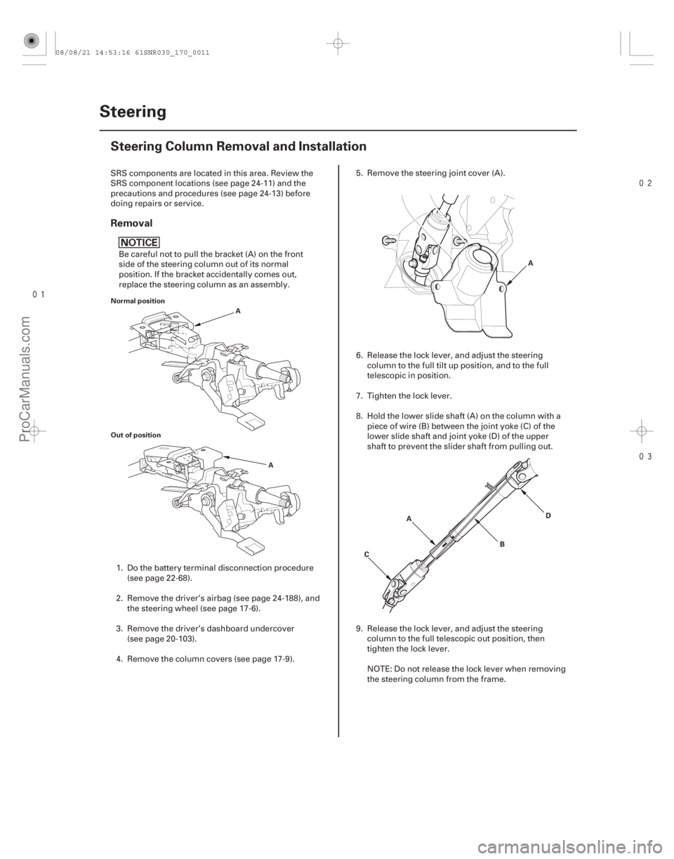
Be careful not to pull the bracket (A) on the front
side of the steering column out of its normal
position. If the bracket accidentally comes out,
replace the steering column as an assembly.
1. Do the battery terminal disconnection procedure (see page 22-68).
2. Remove the driver’s airbag (see page 24-188), and the steering wheel (see page 17-6).
3. Remove the driver’s dashboard undercover (see page 20-103).
4. Remove the column covers (see page 17-9). 5. Remove the steering joint cover (A).
6. Release the lock lever, and adjust the steering
column to the full tilt up position, and to the full
telescopic in position.
7. Tighten the lock lever.
8. Hold the lower slide shaft (A) on the column with a piece of wire (B) between the joint yoke (C) of the
lower slide shaft and joint yoke (D) of the upper
shaft to prevent the slider shaft from pulling out.
9. Release the lock lever, and adjust the steering column to the full telescopic out position, then
tighten the lock lever.
NOTE: Do not release the lock lever when removing
the steering column from the frame.
08/08/21 14:53:16 61SNR030_170_0011
ProCarManuals.com
DYNOMITE -2009-
Page 1335 of 2893
����
17-13
A
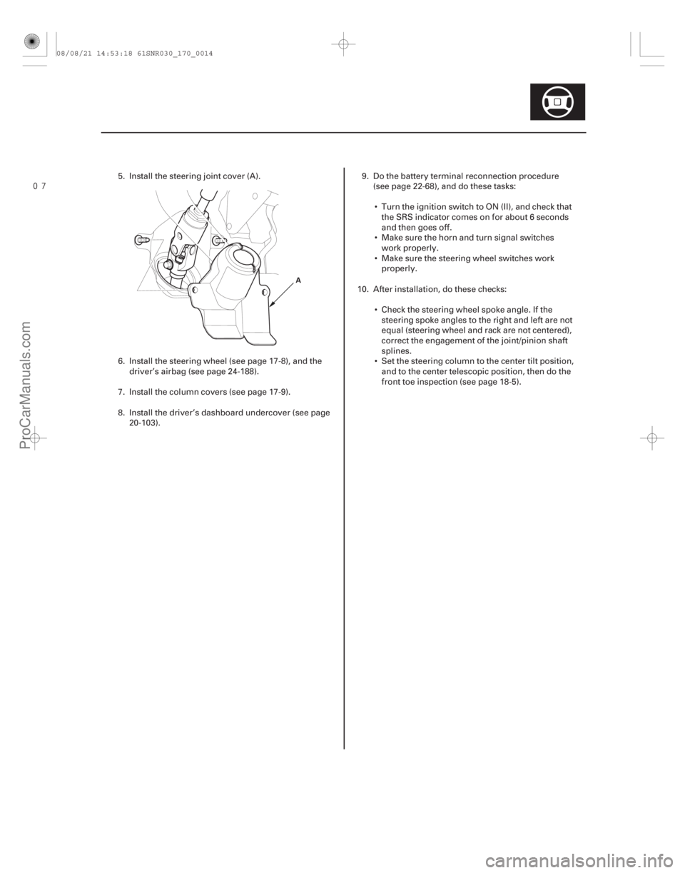
5. Install the steering joint cover (A).
6. Install the steering wheel (see page 17-8), and thedriver’s airbag (see page 24-188).
7. Install the column covers (see page 17-9).
8. Install the driver’s dashboard undercover (see page 20-103). 9. Do the battery terminal reconnection procedure
(see page 22-68), and do these tasks:
Turn the ignition switch to ON (II), and check that the SRS indicator comes on for about 6 seconds
and then goes off.
Make sure the horn and turn signal switches work properly.
Make sure the steering wheel switches work properly.
10. After installation, do these checks: Check the steering wheel spoke angle. If thesteering spoke angles to the right and left are not
equal (steering wheel and rack are not centered),
correct the engagement of the joint/pinion shaft
splines.
Set the steering column to the center tilt position, and to the center telescopic position, then do the
front toe inspection (see page 18-5).
08/08/21 14:53:18 61SNR030_170_0014
ProCarManuals.com
DYNOMITE -2009-
Page 1344 of 2893
���
����
How to Retrieve DTCs
How to Clear DTCs
17-21
A A
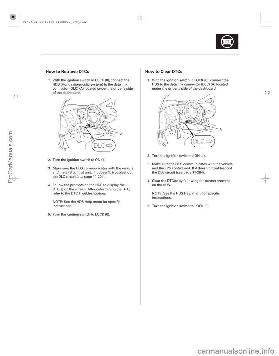
1. With the ignition switch in LOCK (0), connect the
HDS (Honda diagnostic system) to the data link
connector (DLC) (A) located under the driver’s side
of the dashboard.
2. Turn the ignition switch to ON (II).
3. Make sure the HDS communicates with the vehicle and the EPS control unit. If it doesn’t, troubleshoot
the DLC circuit (see page 11-204).
4. Follow the prompts on the HDS to display the DTC(s) on the screen. After determining the DTC,
refer to the DTC Troubleshooting.
NOTE: See the HDS Help menu for specific
instructions.
5. Turn the ignition switch to LOCK (0). 1. With the ignition switch in LOCK (0), connect the
HDS to the data link connector (DLC) (A) located
under the driver’s side of the dashboard.
2. Turn the ignition switch to ON (II).
3. Make sure the HDS communicates with the vehicle and the EPS control unit. If it doesn’t, troubleshoot
the DLC circuit (see page 11-204).
4. Clear the DTC(s) by following the screen prompts on the HDS.
NOTE: See the HDS Help menu for specific
instructions.
5. Turn the ignition switch to LOCK (0).
08/08/21 14:53:59 61SNR030_170_0022
ProCarManuals.com
DYNOMITE -2009-
Page 1345 of 2893
�
�
���
�(�#�'�����������
���
�����������
���
�"�����)����
17-22EPS Components
Memorizing the Torque Sensor Neutral Position
A
The torque sensor neutral position must be memorized
whenever the steering gearbox, the torque sensor, the
EPS motor, or the EPS control unit is replaced. Note that
the torque sensor neutral position is not affected when
erasing the DTC.
NOTE: The torque sensor is temperature sensitive.
When memorizing the torque sensor neutral position,
theambienttemperaturemustbeabove20 10°C
(68 18 °F)
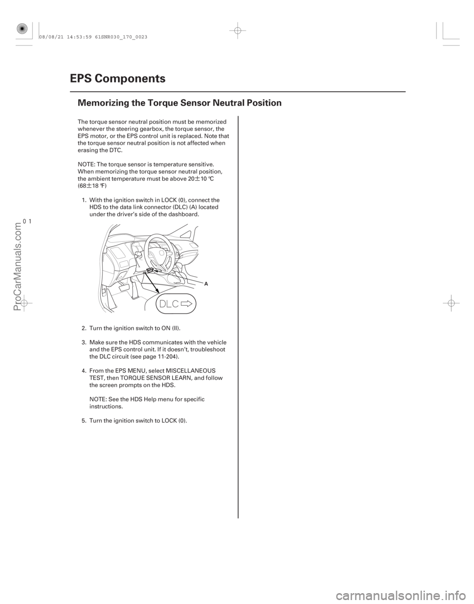
1. With the ignition switch in LOCK (0), connect the HDS to the data link connector (DLC) (A) located
under the driver’s side of the dashboard.
2. Turn the ignition switch to ON (II).
3. Make sure the HDS communicates with the vehicle and the EPS control unit. If it doesn’t, troubleshoot
the DLC circuit (see page 11-204).
4. From the EPS MENU, select MISCELLANEOUS TEST, then TORQUE SENSOR LEARN, and follow
the screen prompts on the HDS.
NOTE: See the HDS Help menu for specific
instructions.
5. Turn the ignition switch to LOCK (0).
08/08/21 14:53:59 61SNR030_170_0023
ProCarManuals.com
DYNOMITE -2009-
Page 1388 of 2893
�Ì
�Ï ���
�(�#�'�����������
���
�����������
�
�
� �����)����
Special Tools Required
Removal
17-65
Steering Gearbox Removal and Installation
A
Ball joint remover, 28 mm 07MAC-SL0A202
Engine hanger adapter
VSB02C000015
Front subframe adaptor VSB02C000016
2006 Civic engine hanger VSB02C000025
Engine support hunger, A and Reds AAR-T1256 : These special tools are available through Honda
Canada Inc. Technical Tools Department; FAX 866-
398-8665/e-mail: ch_technicaltools ch. honda. com
Note these items during removal: Use solvent and a brush, wash any oil and dirt off the end of the steering gearbox. Avoid any electrical
parts. Blow dry with compressed air.
Be sure to remove the steering wheel before disconnecting the steering joint, or damage to the
cable reel may occur.
1. Do the battery terminal disconnection procedure (see page 22-68).
2. Raise the front of the vehicle, and support it with safety stands in the proper locations (see page
1-11).
3. Remove the front wheels.
4. Remove the driver’s airbag (see page 24-188), and the steering wheel (see page 17-6).
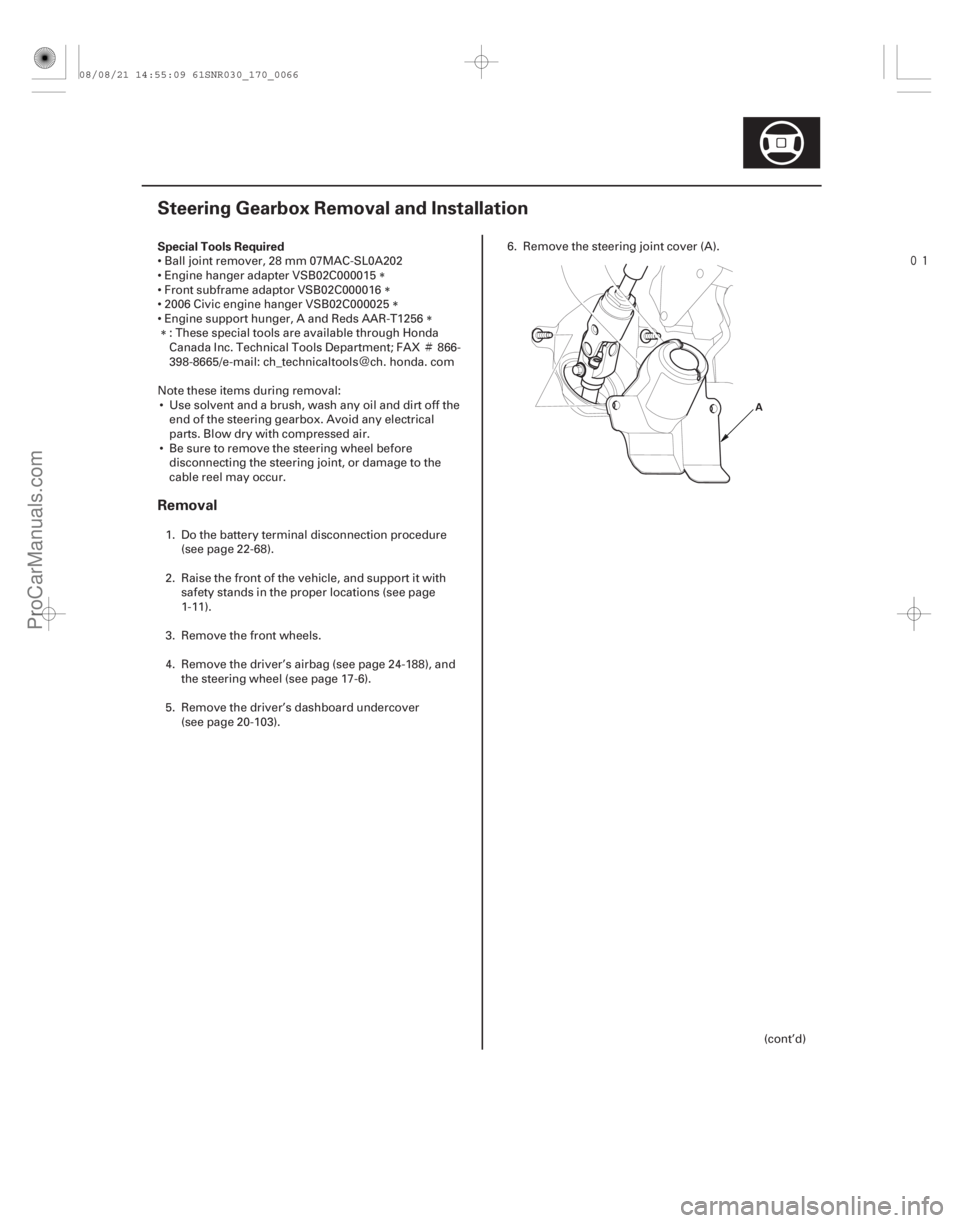
5. Remove the driver’s dashboard undercover (see page 20-103). 6. Remove the steering joint cover (A).
(cont’d)
08/08/21 14:55:09 61SNR030_170_0066
ProCarManuals.com
DYNOMITE -2009-