Page 1542 of 2893
�
��
System IndicatorABS Indicator
Brake System Indicator
19-49
General Troubleshooting Information
AB
This system has two indicators: ABS indicator")
���
�(�#�'�����������
���������������������������)�
��
System IndicatorABS Indicator
Brake System Indicator
19-49
General Troubleshooting Information
AB
This system has two indicators: ABS indicator (A)
Brake system indicator (B)
When the system is OK, each indicator comes on for
about 2 seconds after turning the ignition switch to
ON (II), then goes off.
When the system detects a problem, a DTC is set and,
depending upon the failure, the ABS modulator-control
unit determines which indicator(s) are turned on. If the
problem goes away (system returns to normal), the
indicator(s) are controlled in the following way
depending upon the DTC that is set: The indicator(s) come on and stay on when the ignition switch is ON (II).
The indicator(s) automatically go off.
The indicator(s) go off after the vehicle is driven. The ABS indicator comes on when the ABS function is
lost. The brakes still work like a conventional system.
The brake system indicator comes on when the EBD
function is lost, the parking brake is applied, and/or the
brake fluid level is low.
NOTE: If two or more wheel speed sensors fail, the
brake system indicator comes on.
(cont’d)
08/08/21 15:02:15 61SNR030_190_0049
ProCarManuals.com
DYNOMITE -2009-
Page 1551 of 2893
���
System Outline
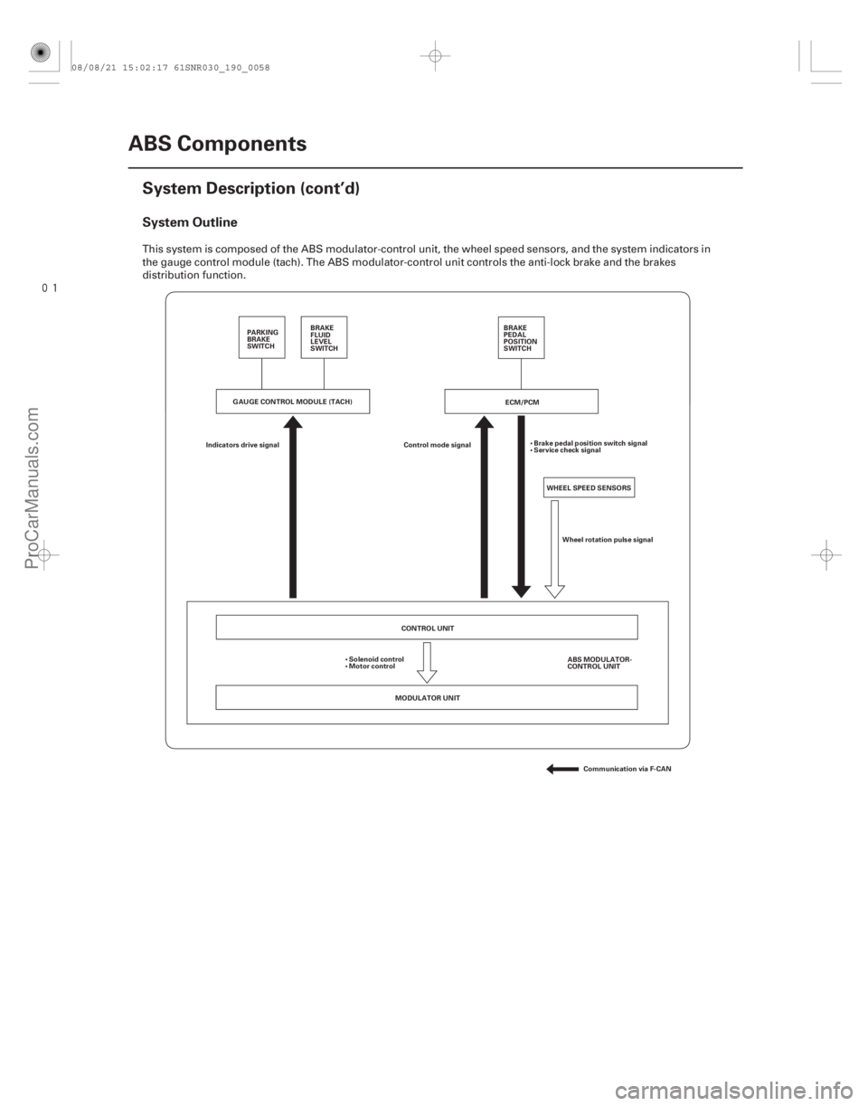
19-58ABS Components
System Description (cont’d)
ECM/PCM
WHEEL SPEED SENSORS
Control mode signal
Indicators drive signal Brake pedal position switch signal
Service check signal
Wheel rotation pulse signal
CONTROL UNIT
MODULATOR UNIT ABS MODULATOR-
CONTROL UNIT
Solenoid control
Motor control
Communication via F-CAN
PARKING
BRAKE
SWITCH
BRAKE
FLUID
LEVEL
SWITCH BRAKE
PEDAL
POSITION
SWITCH
GAUGE CONTROL MODULE (TACH)
This system is composed of the ABS modulator-control unit, the wheel speed sensors, and the system indicators in
the gauge control module (tach). The ABS modulator-control unit controls the anti-lock brake and the brakes
distribution function.
08/08/21 15:02:17 61SNR030_190_0058
ProCarManuals.com
DYNOMITE -2009-
Page 1589 of 2893
����
System IndicatorABS Indicator
Brake System Indicator
VSA Indicator
VSA Activation Indicator
19-97
General Troubleshooting Information
A
D B
C
Thi")
���
�(�#�'���������������
�����������������������)����
System IndicatorABS Indicator
Brake System Indicator
VSA Indicator
VSA Activation Indicator
19-97
General Troubleshooting Information
A
D B
C
This system has four indicators:
ABS indicator (A)
Brake system indicator (B)
VSA indicator (C)
VSA activation indicator (D)
When the system is OK, each indicator comes on for
about 2 seconds after turning the ignition switch to
ON (II), then goes off.
When the system detects a problem, a DTC is set and,
depending upon the failure, the VSA modulator-control
unit determines which indicator(s) are turned on. If the
problem goes away (system returns to normal), the
indicator(s) are controlled in the following way
depending upon the DTC that is set: The indicator(s) come on and stay on when the ignition switch is ON (II).
The indicator(s) automatically go off.
The indicator(s) go off after the vehicle is driven. The ABS indicator comes on when the ABS function is
lost. The brakes still work like a conventional system.
The brake system indicator comes on when the EBD
function is lost, the parking brake is applied, and/or the
brake fluid level is low.
NOTE: If two or more wheel speed sensors fail, the
brake system indicator comes on.
The VSA indicator comes on when the VSA function is
lost.
The VSA activation indicator blinks when the VSA
function is activating. The VSA activation indicator
comes on and stays on when the VSA is turned OFF by
using the VSA OFF switch, or when the VSA function is
lost.
(cont’d)
08/08/21 15:04:50 61SNR030_190_0097
ProCarManuals.com
DYNOMITE -2009-
Page 1600 of 2893

CONTROL UNIT
MODULATOR UNIT VSA MODULATOR-
CONTROL UNIT
Brake pressure
signal
Solenoid control
Motor control
Commun")
����
System Outline
19-108VSA System Components
System Description (cont’d)
CONTROL UNIT
MODULATOR UNIT VSA MODULATOR-
CONTROL UNIT
Brake pressure
signal
Solenoid control
Motor control
Communication via F-CAN
VSA
OFF
SWITCH
PARKING
BRAKE
SWITCH BRAKE
FLUID
LEVEL
SWITCH
WHEEL SPEED SENSOR
Engine torque control request
Control mode signal
VSA control enable/disable
Throttle open angle signal
Engine revolution signal
Brake pedal
position switch signal
Service check signal
Gear position signal
Wheel rotation
pulse signal
ECM/PCM
BRAKE
PEDAL
POSITION
SWITCH
GAUGE CONTROL MODULE (TACH)
YAW RATE-LATERAL
ACCELERATION
SENSORSTEERING ANGLE
SENSOR
VSAOFFswitchsignal
Parking brake switch signal
Brake fluid level switch signal
Yaw rate signal
Lateral acceleration signal Steering angle signal
Indicator drive signal
Buzzer request signal*
*: ’09 model
This system is composed of the VSA modulator-control unit, the wheel speed sensors, the steering angle sensor, the
yaw rate-lateral acceleration sensor, and the system indicators in the gauge control module (tach). The VSA
modulator-control unit controls the ABS, EBD, TCS, VSA, and brake assist with the brake pressure of each wheel and
reduces engine torque.
08/08/21 15:04:53 61SNR030_190_0108
ProCarManuals.com
DYNOMITE -2009-
Page 2033 of 2893

Answer Back Response Operation
Wiper/Washer
Collision Detection Signal (CDS)
InputOutput
Input Output
Input Output
Input Output
Input Output
I")
Security Alarm System
Key-in Reminder
Key Interlock (A/T)
Answer Back Response Operation
Wiper/Washer
Collision Detection Signal (CDS)
InputOutput
Input Output
Input Output
Input Output
Input Output
Input Output
22-87
The MICU controls the lighting system and horn based upon B-CAN signals and input signals from the each switch.
MICU IG1 power supply Ignition key switch
Audio switch
Driver’s door switch
Front passenger’s door switch
Left rear door switch
Right rear door switch
Trunk lid latch switch
Driver’s door key cylinder switch (UNLOCK)
Driver’s door lock knob switch (UNLOCK)
Front passenger’s door lock knob switch (UNLOCK)
Left rear door lock knob switch (UNLOCK)
Right rear door lock knob switch (UNLOCK)
Hood switch Horn
Headlights
Parking lights
Side marker lights
License plate lights
Taillights
B-CAN Keyless LOCK signal Door lock signal
The MICU controls the door lock actuators based upon ignition key switch, the driver’s door switch, and driver’s door lock knob switch signals. MICU Ignition key switch Driver’s door switch
Driver’s door lock knob switch Door lock actuator (LOCK/UNLOCK)
Driver’s door lock actuator (UNLOCK)
The MICU controls the key interlock solenoid based upon IG1, transmission range switch, and park-pin switch signals. MICU Ignition switch ACC Transmission range switch (P position)
Park-pin switch Key interlock solenoid
The MICU controls the lighting system and horn based upon B-CAN signals. B-CAN Answer back signals (headlight low, horn, parking lights) Horn Headlights
Parking lights
Side marker lights
License plate lights
Taillights
The MICU controls the wiper motor and the washer motor based upon IG1 and wiper/washer switch signals. MICU IG1 power supply Wiperswitch(INTandLO)
Wiper switch (LO and HI)
Wiper switch (MIST)
Washer switch
Wiper intermittent speed Wiper motor
Washer motor
The MICU controls the door lock actuators based upon IG1 and B-CAN signals. MICU IG1 power supply Door lock (LOCK/UNLOCK)
B-CAN SRS signal (front, side and rear) Impact sensors
(cont’d)
08/08/21 14:24:09 61SNR030_220_0089
ProCarManuals.com
DYNOMITE -2009-