Page 8 of 2893
��������� �(�#�'���������������������������������������)����
1-7
Danger/Warning/Caution Label Locations
FRONT PASSENGER
AIRBAG MODULE
DANGER
FRONT SEAT BELT
TENSIONER CAUTION SRS WARNING
INFORMATION
MONITOR NOTICE
STEERING COLUMN
NOTICE
SIDE AIRBAG CAUTION SIDE AIRBAG
MODULE DANGERFRONTSEATBELT
BUCKLE TENSIONER
CAUTION
Front Passenger’s Compartment:
Steering Wheel: CABLE REEL CAUTION DRIVER AIRBAG
MODULE DANGER
DRIVER AIRBAG
MODULE DANGER Rear Passenger’s Compartment:
ROOF-SIDE AIRBAG
MODULE DANGER
(cont’d)
Located on driver’s and
passenger’s doorjamb
08/08/21 14:06:00 61SNR030_010_0007
ProCarManuals.com
DYNOMITE -2009-
Page 98 of 2893

���
����
����
�(�#�'�����������
�����������
���������������)����
4-49
Cruise Control Combination Switch Test/Replacement
Terminal
Position Cruise control
main switch (ON) 5
37
Cancel
(PRESSED) 64
Cruise control
main switch (OFF) Set/decel
(PRESSED)
Resume/accel
(PRESSED)
SRS components are located in this area. Review the
SRS component locations (see page 24-11), and
precautions and procedures (see page 24-13), before
doing repairs or service.
1. Remove the driver’s airbag (see page 24-188).
2. Remove the steering wheel trim.
3. Remove the cruise control combination switch. 4. Check for continuity between the terminals in each
cruise control combination switch position
accordingtothetable.
If there is continuity, and it matches the table, but the cruise control combination switch failure
occurred on the cruise control input test, check
and repair the wire harness on the switch circuit.
If there is no continuity in one or more positions, replace the cruise control combination switch.
Wire side of
female terminals
08/08/21 14:10:51 61SNR030_040_0050
ProCarManuals.com
DYNOMITE -2009-
Page 1326 of 2893
����
�(�#�'���������������������������������������)����
17-3
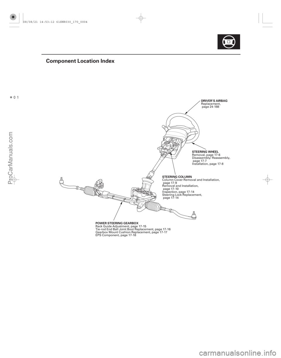
Component Location Index
DRIVER’S AIRBAG
POWER STEERING GEARBOX STEERING COLUMN
STEERING WHEELReplacement,
page 24-188
Rack Guide Adjustment, page 17-15
Tie-rod End Ball Joint Boot Replacement, page 17-16
Gearbox Mount Cushion Replacement, page 17-17
EPS Component, page 17-18 Column Cover Removal and Installation,
page 17-9
Removal and Installation, page 17-10
Inspection, page 17-14
Steering Lock Replacement, page 17-14 Removal, page 17-6
Disassembly/ Reassembly,
page 17-7
Installation, page 17-8
08/08/21 14:53:12 61SNR030_170_0004
ProCarManuals.com
DYNOMITE -2009-
Page 1329 of 2893
���
����
����
�(�#�'���������������������������
���
� �����)����
17-6 Steering
Steering Wheel Removal
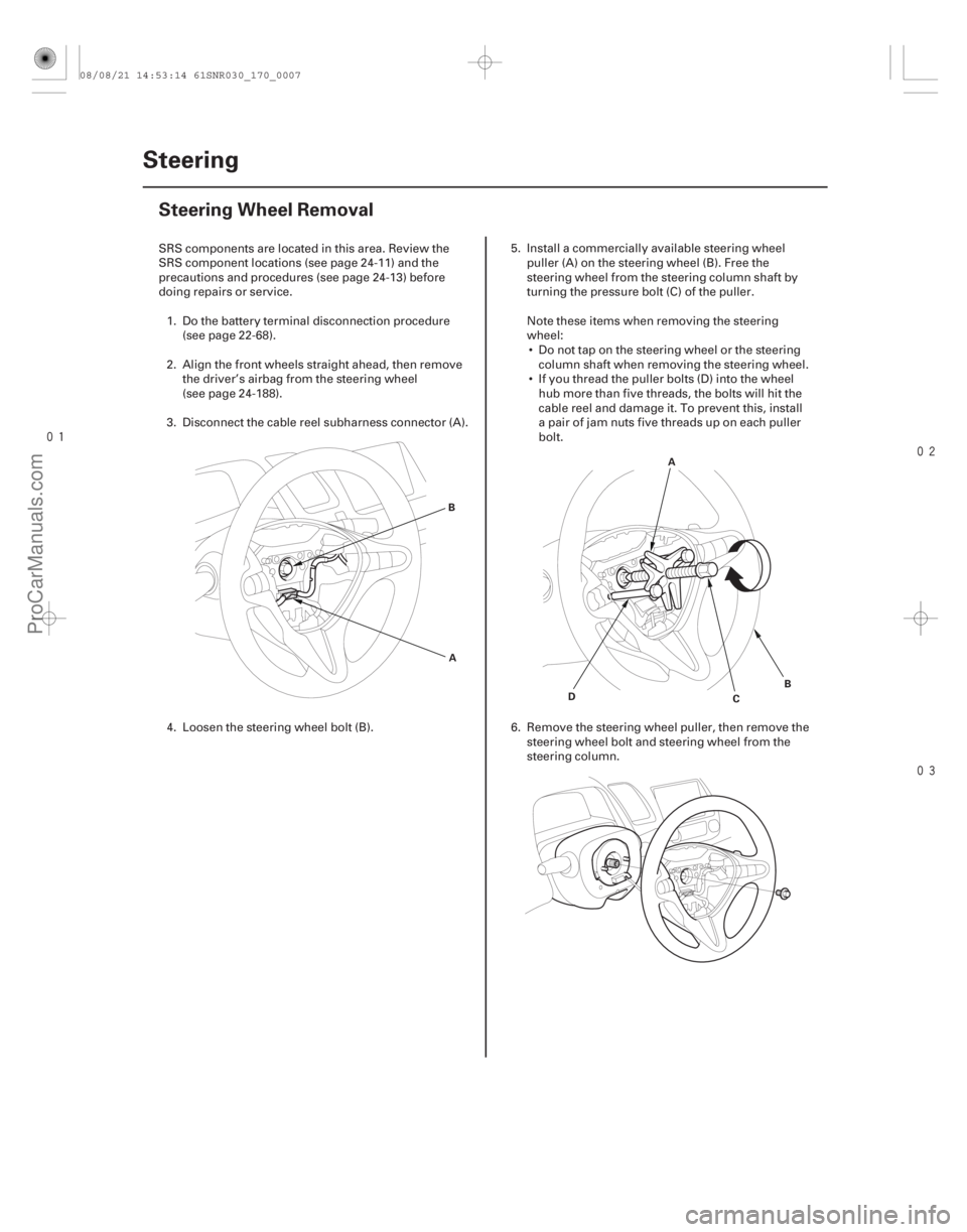
A
B
A
D B
C
SRS components are located in this area. Review the
SRS component locations (see page 24-11) and the
precautions and procedures (see page 24-13) before
doing repairs or service.
1. Do the battery terminal disconnection procedure (see page 22-68).
2. Align the front wheels straight ahead, then remove the driver’s airbag from the steering wheel
(see page 24-188).
3. Disconnect the cable reel subharness connector (A).
4. Loosen the steering wheel bolt (B). 5. Install a commercially available steering wheel
puller (A) on the steering wheel (B). Free the
steering wheel from the steering column shaft by
turning the pressure bolt (C) of the puller.
Note these items when removing the steering
wheel: Do not tap on the steering wheel or the steering column shaft when removing the steering wheel.
If you thread the puller bolts (D) into the wheel hub more than five threads, the bolts will hit the
cable reel and damage it. To prevent this, install
a pair of jam nuts five threads up on each puller
bolt.
6. Remove the steering wheel puller, then remove the steering wheel bolt and steering wheel from the
steering column.
08/08/21 14:53:14 61SNR030_170_0007
ProCarManuals.com
DYNOMITE -2009-
Page 1332 of 2893
���
����
����
�(�#�'���������������������������
���
� �����)����
Removal
17-10 Steering
Steering Column Removal and Installation
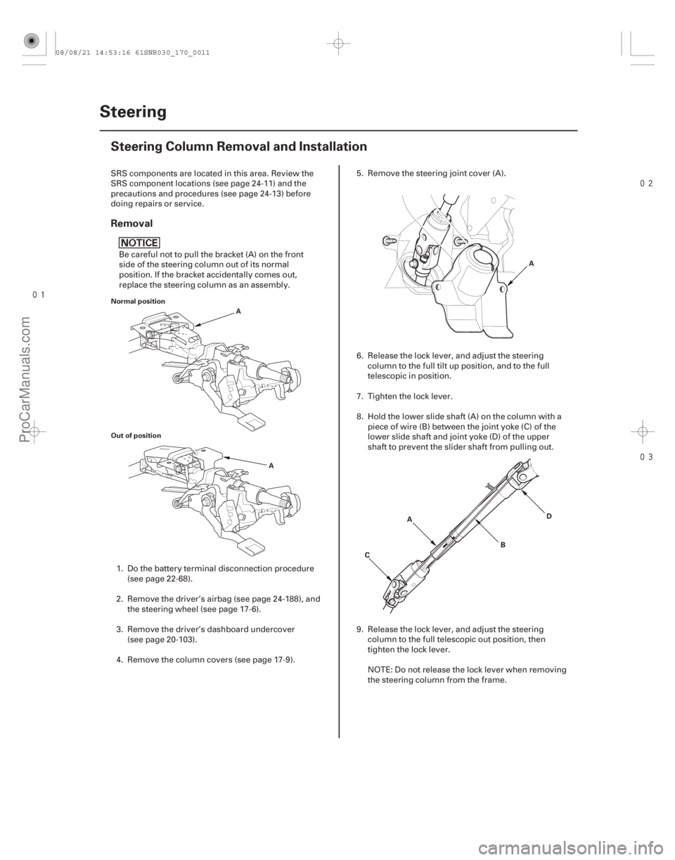
Normal position
Out of position
A
A
A
A B
C D
SRS components are located in this area. Review the
SRS component locations (see page 24-11) and the
precautions and procedures (see page 24-13) before
doing repairs or service.
Be careful not to pull the bracket (A) on the front
side of the steering column out of its normal
position. If the bracket accidentally comes out,
replace the steering column as an assembly.
1. Do the battery terminal disconnection procedure (see page 22-68).
2. Remove the driver’s airbag (see page 24-188), and the steering wheel (see page 17-6).
3. Remove the driver’s dashboard undercover (see page 20-103).
4. Remove the column covers (see page 17-9). 5. Remove the steering joint cover (A).
6. Release the lock lever, and adjust the steering
column to the full tilt up position, and to the full
telescopic in position.
7. Tighten the lock lever.
8. Hold the lower slide shaft (A) on the column with a piece of wire (B) between the joint yoke (C) of the
lower slide shaft and joint yoke (D) of the upper
shaft to prevent the slider shaft from pulling out.
9. Release the lock lever, and adjust the steering column to the full telescopic out position, then
tighten the lock lever.
NOTE: Do not release the lock lever when removing
the steering column from the frame.
08/08/21 14:53:16 61SNR030_170_0011
ProCarManuals.com
DYNOMITE -2009-
Page 1335 of 2893
����
17-13
A
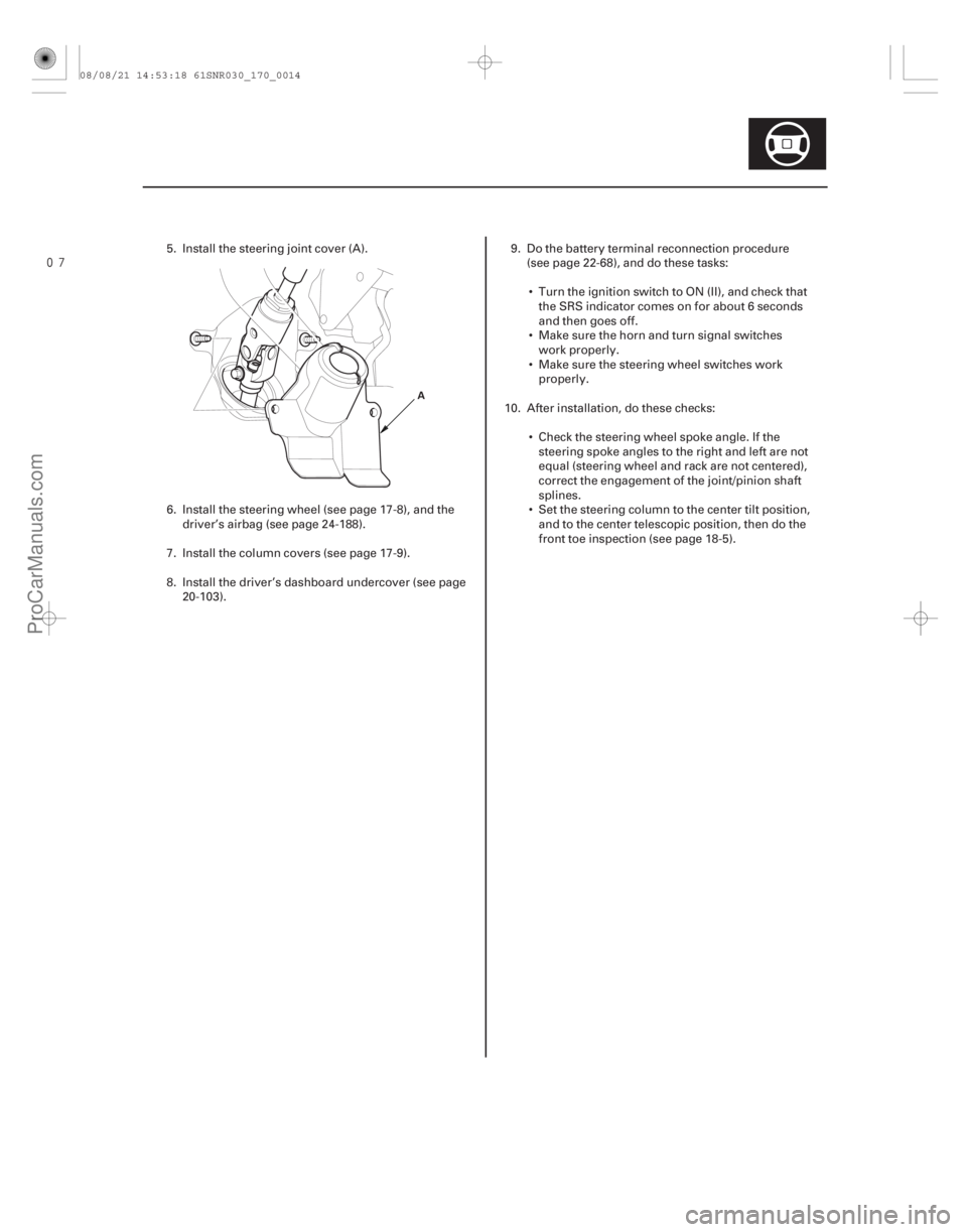
5. Install the steering joint cover (A).
6. Install the steering wheel (see page 17-8), and thedriver’s airbag (see page 24-188).
7. Install the column covers (see page 17-9).
8. Install the driver’s dashboard undercover (see page 20-103). 9. Do the battery terminal reconnection procedure
(see page 22-68), and do these tasks:
Turn the ignition switch to ON (II), and check that the SRS indicator comes on for about 6 seconds
and then goes off.
Make sure the horn and turn signal switches work properly.
Make sure the steering wheel switches work properly.
10. After installation, do these checks: Check the steering wheel spoke angle. If thesteering spoke angles to the right and left are not
equal (steering wheel and rack are not centered),
correct the engagement of the joint/pinion shaft
splines.
Set the steering column to the center tilt position, and to the center telescopic position, then do the
front toe inspection (see page 18-5).
08/08/21 14:53:18 61SNR030_170_0014
ProCarManuals.com
DYNOMITE -2009-
Page 1341 of 2893
���
��������
�(�#�'���������������������������
���
� �����)����
17-8 Steering
Steering Wheel Installation
A
B
A D
B
C A
39 N·m
(4.0 kgf·m,
29 lbf·ft)
B
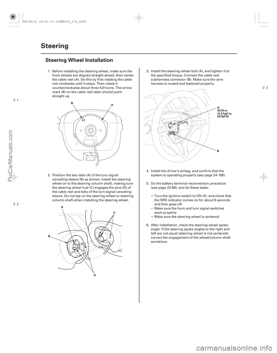
1. Before installing the steering wheel, make sure the front wheels are aligned straight ahead, then center
the cable reel (A). Do this by first rotating the cable
reel clockwise until it stops. Then rotate it
counterclockwise about three full turns. The arrow
mark (B) on the cable reel label should point
straight up.
2. Position the two tabs (A) of the turn signal canceling sleeve (B) as shown. Install the steering
wheel on to the steering column shaft, making sure
the steering wheel hub (C) engages the pins (D) of
the cable reel and tabs of the turn signal canceling
sleeve. Do not tap on the steering wheel or steering
column shaft when installing the steering wheel. 3. Install the steering wheel bolt (A), and tighten it to
the specified torque. Connect the cable reel
subharness connector (B). Make sure the wire
harness is routed and fastened properly.
4. Install the driver’s airbag, and confirm that the system is operating properly (see page 24-188).
5. Do the battery terminal reconnection procedure (see page 22-68), and do these tasks:
Turn the ignition switch to ON (II), and check that the SRS indicator comes on for about 6 seconds
and then goes off.
Make sure the horn and turn signal switches work properly.
Make sure the steering wheel is centered.
6. After installation, check the steering wheel spoke angle. If the steering spoke angles to the right and
left are not equal (steering wheel is not centered),
correct the engagement of the wheel/column shaft
serrations.
08/08/21 14:53:15 61SNR030_170_0009
ProCarManuals.com
DYNOMITE -2009-
Page 1388 of 2893
�Ì
�Ï ���
�(�#�'�����������
���
�����������
�
�
� �����)����
Special Tools Required
Removal
17-65
Steering Gearbox Removal and Installation
A
Ball joint remover, 28 mm 07MAC-SL0A202
Engine hanger adapter
VSB02C000015
Front subframe adaptor VSB02C000016
2006 Civic engine hanger VSB02C000025
Engine support hunger, A and Reds AAR-T1256 : These special tools are available through Honda
Canada Inc. Technical Tools Department; FAX 866-
398-8665/e-mail: ch_technicaltools ch. honda. com
Note these items during removal: Use solvent and a brush, wash any oil and dirt off the end of the steering gearbox. Avoid any electrical
parts. Blow dry with compressed air.
Be sure to remove the steering wheel before disconnecting the steering joint, or damage to the
cable reel may occur.
1. Do the battery terminal disconnection procedure (see page 22-68).
2. Raise the front of the vehicle, and support it with safety stands in the proper locations (see page
1-11).
3. Remove the front wheels.
4. Remove the driver’s airbag (see page 24-188), and the steering wheel (see page 17-6).
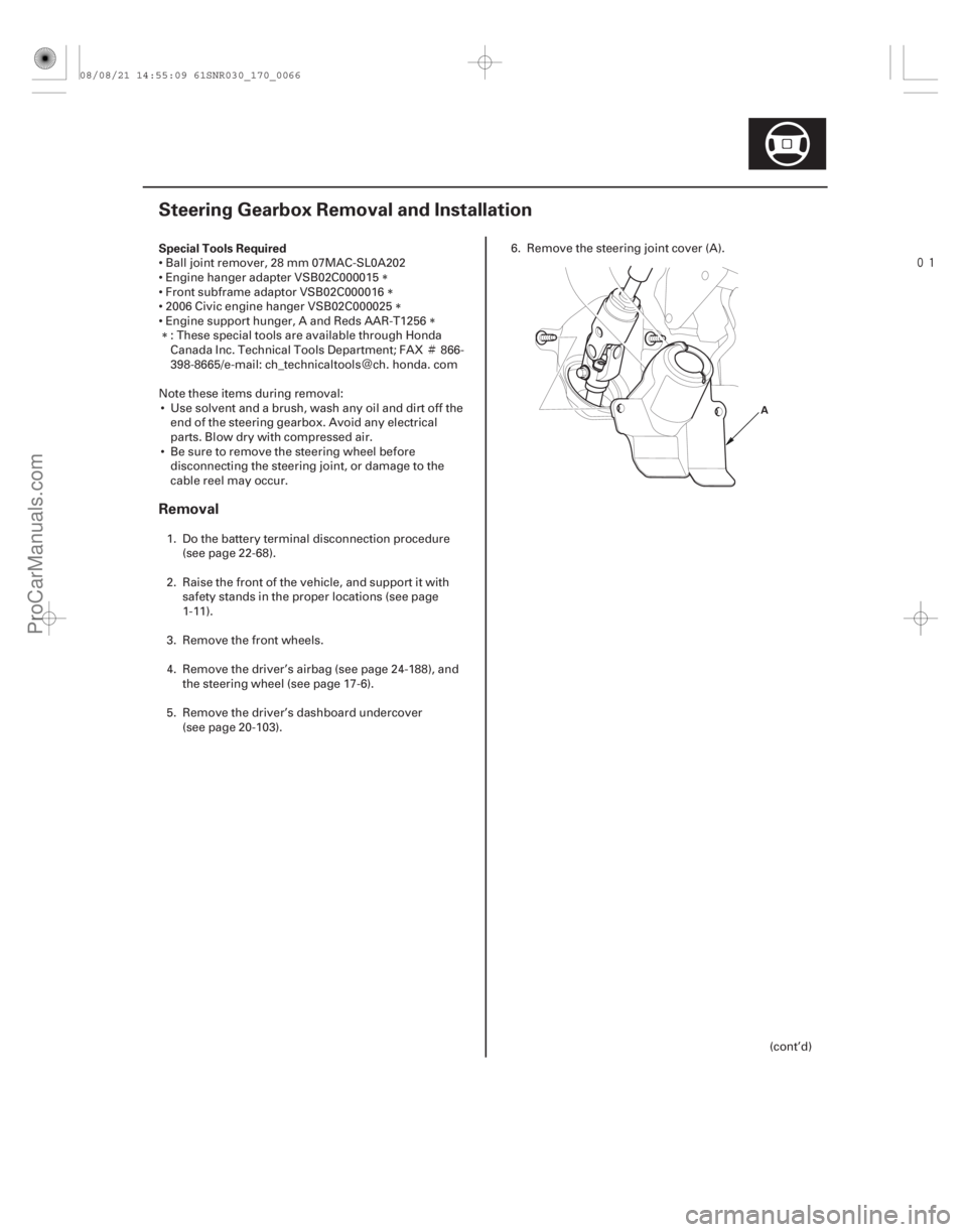
5. Remove the driver’s dashboard undercover (see page 20-103). 6. Remove the steering joint cover (A).
(cont’d)
08/08/21 14:55:09 61SNR030_170_0066
ProCarManuals.com
DYNOMITE -2009-