Page 1718 of 5135
± DIAGNOSTICSMULTIPLEX COMMUNICATION SYSTEM
05±1665
AVENSIS REPAIR MANUAL (RM1018E)
(a) Disconnect the A13 ECU, E9 or E10 ECM and I14 J/B connectors.
(b) Check the voltage or resistance of each terminal of the wire harness side connector.
Standard:
Symbols (Terminal No.)Wiring ColorConditionSpecified Condition
GND (A13±40) ±
Body groundW±B ± body groundConstantBelow 1 �
+B �A13±2) ±
GND (A13±40)W±R ± W±BConstant10 to 14 V
MPX± (A13±29) ±
MPX1 (I14±11)P ± P
*1
MPX+ (A13±9) ±
MPX2 (E10±29)P±B ± P±B
ConstantBelow 1�*2
MPX+ (A13±9) ±
MPX2 (E9±29)P±B ± P±B
ConstantBelow 1 �
*3
MPX+ (A13±9) ±
MPX2 (E9±21)P±B ± P±B
HINT:
*
1: 1AZ±FSE
*
2: 1AZ±FE, 1ZZ±FE, 3ZZ±FE
*
3: 1CD±FTV
If the result is not as specified, there may be a malfunction on the wire harness side.
Page 1720 of 5135

B69311
T6
C10 Combination Meter Assy
(Combination Meter ECU)Theft Warning ECU Assy
± DIAGNOSTICSMULTIPLEX COMMUNICATION SYSTEM
05±1667
AVENSIS REPAIR MANUAL (RM1018E)
(a) Disconnect the A15, A16 ECU, E9 or E10 ECM and I14 J/B connectors.
(b) Check the voltage or resistance of each terminal of the wire harness side connector.
Standard:
Symbols (Terminal No.)Wiring ColorConditionSpecified Condition
GND (A16±13) ±
Body groundW±B ± Body groundConstantBelow 1 �
+B (A16±24) ±
GND (A16±13)W±R ± W±BConstant10 to 14 V
MPX± (A15±20) ±
MPX1 (I14±11)P ± P
*1
MPX+ (A15±10) ±
MPX2 (E10±29)P±B ± P±B
ConstantBelow 1�*2
MPX+ (A15±10) ±
MPX2 (E9±29)P±B ± P±B
ConstantBelow 1 �
*3
MPX+ (A15±10) ±
MPX2 (E9±21)P±B ± P±B
HINT:
*
1: 1AZ±FSE
*
2: 1AZ±FE, 1ZZ±FE, 3ZZ±FE
*
3: 1CD±FTV
If the result is not as specified, there may be a malfunction on the wire harness side.
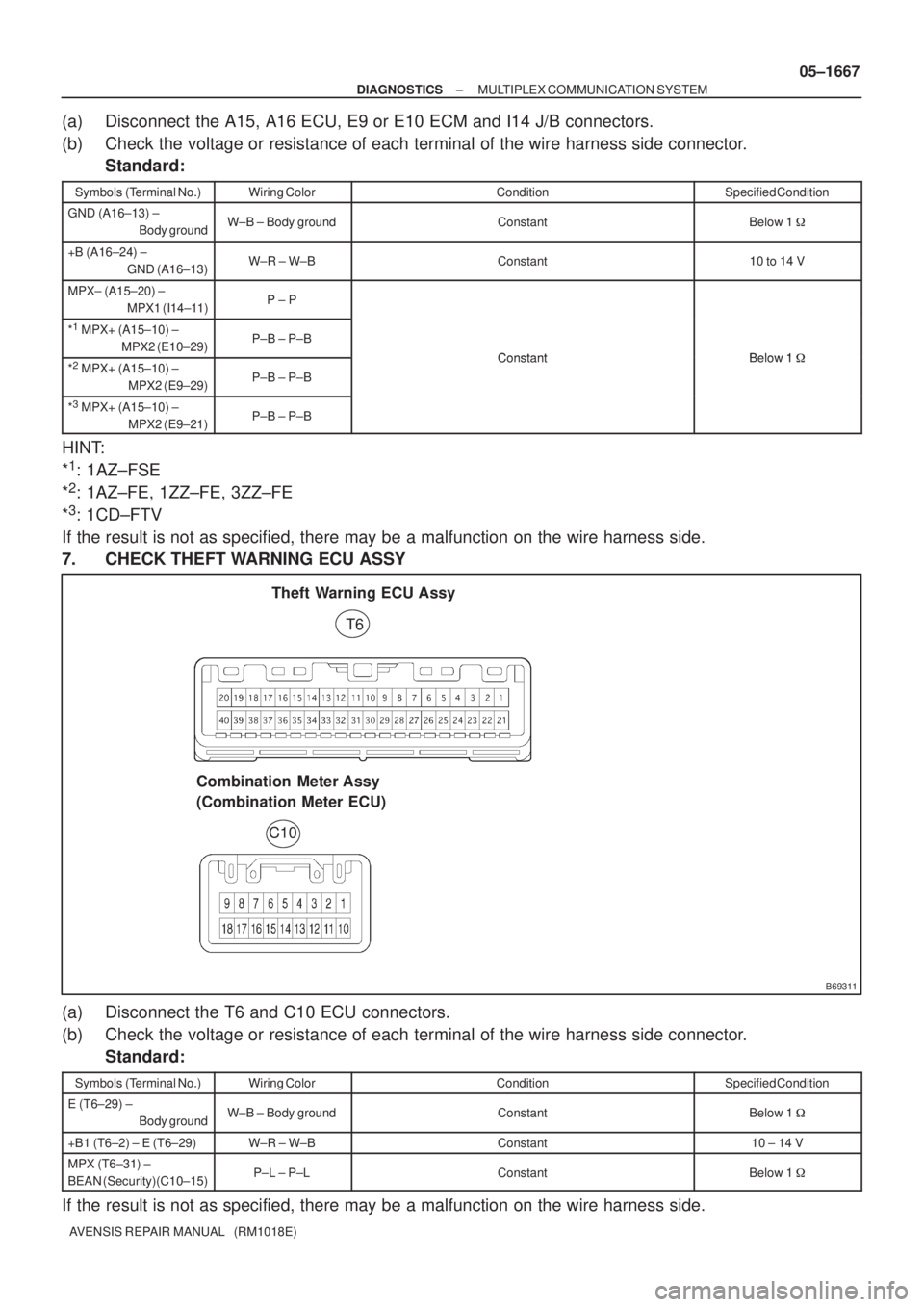
7. CHECK THEFT WARNING ECU ASSY
(a) Disconnect the T6 and C10 ECU connectors.
(b) Check the voltage or resistance of each terminal of the wire harness side connector.
Standard:
Symbols (Terminal No.)Wiring ColorConditionSpecified Condition
E (T6±29) ±
Body groundW±B ± Body groundConstantBelow 1 �
+B1 (T6±2) ± E (T6±29)W±R ± W±BConstant10 ± 14 V
MPX (T6±31) ±
BEAN (Security)(C10±15)P±L ± P±LConstantBelow 1 �
If the result is not as specified, there may be a malfunction on the wire harness side.
Page 1722 of 5135
± DIAGNOSTICSMULTIPLEX COMMUNICATION SYSTEM
05±1669
AVENSIS REPAIR MANUAL (RM1018E)
(a) Disconnect the C10, C11, T6, ECU, E10 or E9 ECM and I14 connectors.
(b) Check the voltage or resistance of each terminal of the wire harness side connector.
Standard:
Symbols (Terminal No.)Wiring ColorConditionSpecified Condition
POWER EARTH
(C10±17) ±
Body ground
W±B ± Body groundConstantBelow 1 �
+B �C11±20) ±
POWER EARTH
(C10±17)
W±R ± W±BConstant10 to 14 V
*1
BEAN (EFI)
(C10±13) ±
MPX1 (E10±18)
P ± P
*2
BEAN (EFI)
(C10±13) ±
MPX1 (E9±23)
P ± P
*3
BEAN (EFI)
(C10±13) ±
MPX1 (E9±20)
P ± PConstantBelow 1 �
BEAN (BODY)
(C10±14) ±
MPX2 (I14±22)
P±B ± P±B
*4
BEAN (SECURITY)
(C10±15) ±
MPX (T6±31)
P±L ± P±L
HINT:
*
1: 1AZ±FSE
*
2: 1AZ±FE, 1ZZ±FE, 3ZZ±FE
*
3: 1CD±FTV
*
4: w/ Theft deterrent system
If the result is not as specified, there may be a malfunction on the wire harness side.
Page 1728 of 5135

B67699
S+B
IOUT 24
26 L±W
L±B 9 T12
Theft Warning Radar Sensor
6 S+B
IOUT
SOFF7
W±BSSW1
13 LG±B
ID18T6
Theft Warning ECU Assy
T14
Rear Theft Warning
Radar Sensor (IN)
T13
Rear Theft Warning
Radar Sensor (OUT)
IJ DA DK9 6 LG±B L±B L±W
ID1 ID1
W±B 19
SOU+
SOU±GND SIN+
SIN± 2
1
2
18
4
1 53 W
P
L
2 MIN+
MIN±
MOU+
MOU±Instrument Panel J/B Assy Shielded 05±1650
± DIAGNOSTICSTHEFT DETERRENT SYSTEM
AVENSIS REPAIR MANUAL (RM1018E)
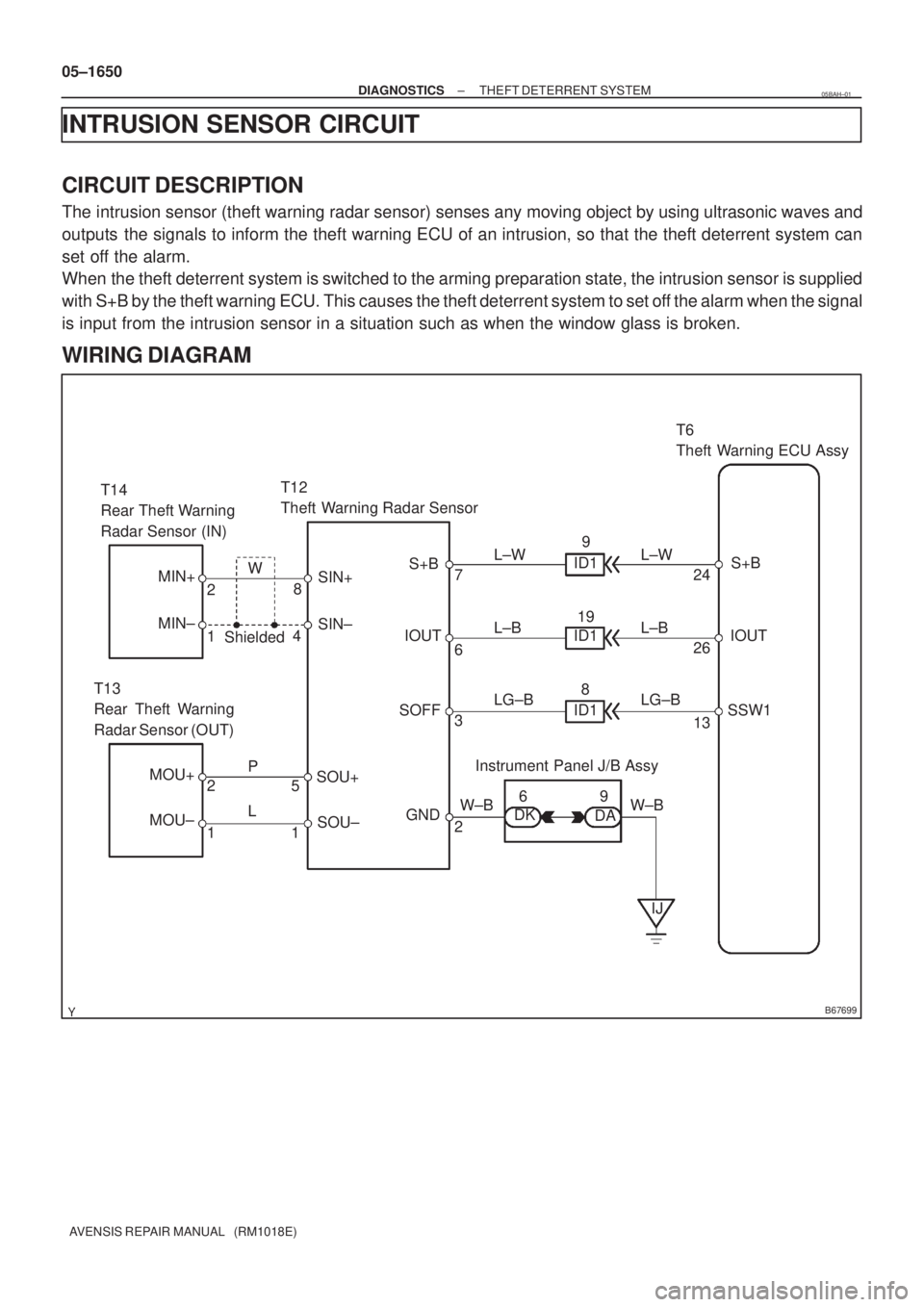
INTRUSION SENSOR CIRCUIT
CIRCUIT DESCRIPTION
The intrusion sensor (theft warning radar sensor) senses any moving object by using ultrasonic waves and
outputs the signals to inform the theft warning ECU of an intrusion, so that the theft deterrent system can
set off the alarm.
When the theft deterrent system is switched to the arming preparation state, the intrusion sensor is supplied
with S+B by the theft warning ECU. This causes the theft deterrent system to set off the alarm when the signal
is input from the intrusion sensor in a situation such as when the window glass is broken.
WIRING DIAGRAM
05BAH±01
Page 1732 of 5135

B67700
CTLS
27 L±R
IM111 T15
Theft Warning Siren Assy
W±R
CI CC7
2
2
4AECU±B2 Fuse Block 10
1 W±R
B*
2
Battery Center J/B Assy
6T6
Theft Warning ECU Assy
BW
+B
3 W±R
B±G*
1
L±R
IM112
GND CONT
6
IP15
B±W B±W
Engine Room R/B
DCC
1 21
1 1A
B*
2B±G*1
4B
Main3
3 11W±B
*
1: Gasoline
*2: 1CD±FTV1
Engine Room
R/B No. 3 Engine Room
J/B No. 4
± DIAGNOSTICSTHEFT DETERRENT SYSTEM
05±1647
AVENSIS REPAIR MANUAL (RM1018E)
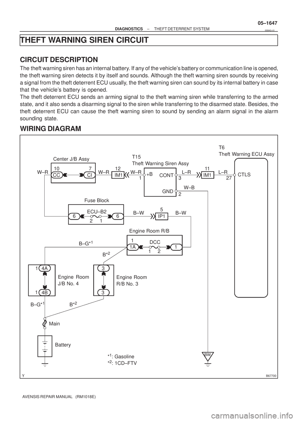
THEFT WARNING SIREN CIRCUIT
CIRCUIT DESCRIPTION
The theft warning siren has an internal battery. If any of the vehicle's battery or communication line is opened,
the theft warning siren detects it by itself and sounds. Although the theft warning siren sounds by receiving
a signal from the theft deterrent ECU usually, the theft warning siren can sound by its internal battery in case
that the vehicle's battery is opened.
The theft deterrent ECU sends an arming signal to the theft warning siren while transferring to the armed
state, and it also sends a disarming signal to the siren while transferring to the disarmed state. Besides, the
theft deterrent ECU can cause the theft warning siren to sound by sending an alarm signal in the alarm
sounding state.
WIRING DIAGRAM
05BAG±01
Page 1735 of 5135
B67701
Battery MainEngine Room R/B12
1T7
Theft Warning ECU Assy
G
HORN
B±G*
1
HORN Relay
G±W20
1H11
Horn
(Low) W
H12
Horn
(High)IE1J26
J/C
B
HORN5 Engine Room R/B No. 2
B G G
32
2 2 2
5
W
1
1A 1
1 3
3
B±G*
1
B*2
B*2
4A
4B1
1
*
1: Gasoline
*2: 1CD±FTV Engine Room
R/B No. 3 Engine
Room J/B
No. 4
G±W 05±1644
± DIAGNOSTICSTHEFT DETERRENT SYSTEM
AVENSIS REPAIR MANUAL (RM1018E)
HORN CIRCUIT
CIRCUIT DESCRIPTION
When the theft deterrent system is transferred from the armed state to the alarm sounding state, the theft
warning ECU switches on the HORN relay causing the horns to sound. The horn sounds at an interval of
0.4 seconds.
WIRING DIAGRAM
05BAF±01
Page 1738 of 5135
B68375
E6
Engine Hood Courtesy Switch
W±B
1 3IO15
DSWH
34 L±RT6
Theft Warning ECU Assy
ECL±R
B67861
Free
(ON)
Pushed
(OFF)
05±1642
± DIAGNOSTICSTHEFT DETERRENT SYSTEM
AVENSIS REPAIR MANUAL (RM1018E)
ENGINE HOOD COURTESY SWITCH CIRCUIT
CIRCUIT DESCRIPTION
The engine hood courtesy switch is installed together with the hood lock assy. This switch comes on when
the engine hood is opened and goes off when the engine hood is closed.
WIRING DIAGRAM
INSPECTION PROCEDURE
1 INSPECT ENGINE HOOD COURTESY SWITCH
(a) Remove the engine hood courtesy switch from the hood
lock assy.
(b) Check the resistance.
Tester ConnectionSwitch PositionSpecified Condition
13Pushed (OFF (Lock))10 k� or higher1 ± 3Free (ON (Unlock))Below 1 �
NG REPAIR OR REPLACE ENGINE HOOD
COURTESY SWITCH
OK
05BAE±01
Page 1740 of 5135

100EX±02
A75903
Air
A79035
VG
EVG
A79035
E2
EMPS
±
ENGINE CONTROL SYSTEM SFI SYSTEM(1ZZ±FE/3ZZ±FE)
10±1
AVENSIS REPAIR MANUAL (RM1018E)
SFI SYSTEM(1ZZ±FE/3ZZ±FE)
ON±VEHICLE INSPECTION
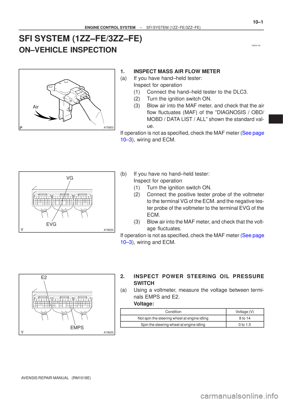
1.INSPECTMASS AIR FLOW METER
(a)If you have hand±held tester:
Inspect for operation
(1)Connect the hand±held tester to the DLC3.
(2)Turn the ignition switch ON.
(3)Blow air into the MAF meter, and check that the airflow fluctuates (MAF) of the ºDIAGNOSIS / OBD/
MOBD / DATA LIST / ALLº shown the standard val-
ue.
If operation is not as specified, check the MAF meter (See page
10±3), wiring and ECM.
(b)If you have no hand±held tester: Inspect for operation
(1)Turn the ignition switch ON.
(2)Connect the positive tester probe of the voltmeterto the terminal VG of the ECM. and the negative tes-
ter probe of the voltmeter to the terminal EVG of the
ECM.
(3)Blow air into the MAF meter, and check that the volt- age fluctuates.
If operation is not as specified, check the MAF meter (See page
10±3), wiring and ECM.
2. INSPECT POWER STEERING OIL PRESSURE SWITCH
(a) Using a voltmeter, measure the voltage between termi-
nals EMPS and E2.
Voltage:
ConditionVoltage (V)
Not spin the steering wheel at engine idling8 to 14
Spin the steering wheel at engine idling0 to 1.5