Page 1632 of 5135
05B0B±02
B65593
I12
B55023
GND
± DIAGNOSTICSENGINE IMMOBILISER SYSTEM
05±1607
AVENSIS REPAIR MANUAL (RM1018E)
TERMINALS OF ECU
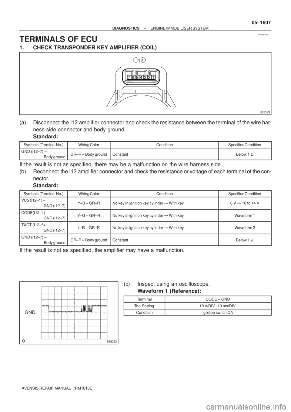
1. CHECK TRANSPONDER KEY AMPLIFIER (COIL)
(a) Disconnect the I12 amplifier connector and check the resistance between the terminal of the wire har-
ness side connector and body ground.
Standard:
Symbols (Terminal No.)Wiring ColorConditionSpecified Condition
GND (I12±7) ±
Body groundGR±R ± Body groundConstantBelow 1 �
If the result is not as specified, there may be a malfunction on the wire harness side.
(b) Reconnect the I12 amplifier connector and check the resistance or voltage of each terminal of the con-
nector.
Standard:
Symbols (Terminal No.)Wiring ColorConditionSpecified Condition
VC5 (I12±1) ±
GND (I12±7)Y±B ± GR±RNo key in ignition key cylinder � With key0 V �10 to 14 V
CODE(I12±4) ±
GND (I12±7)Y±G ± GR±RNo key in ignition key cylinder � With keyWaveform 1
TXCT (I12±5) ±
GND (I12±7)L±R ± GR±RNo key in ignition key cylinder � With keyWaveform 2
GND (I12±7) ±
Body groundGR±R ± Body groundConstantBelow 1 �
If the result is not as specified, the amplifier may have a malfunction.
(c) Inspect using an oscilloscope.
Waveform 1 (Reference):
TerminalCODE ± GND
Tool Setting10 V/DIV., 10 ms/DIV.
ConditionIgnition switch ON
Page 1633 of 5135
B55024
GND
B50659
T8 05±1608
± DIAGNOSTICSENGINE IMMOBILISER SYSTEM
AVENSIS REPAIR MANUAL (RM1018E)
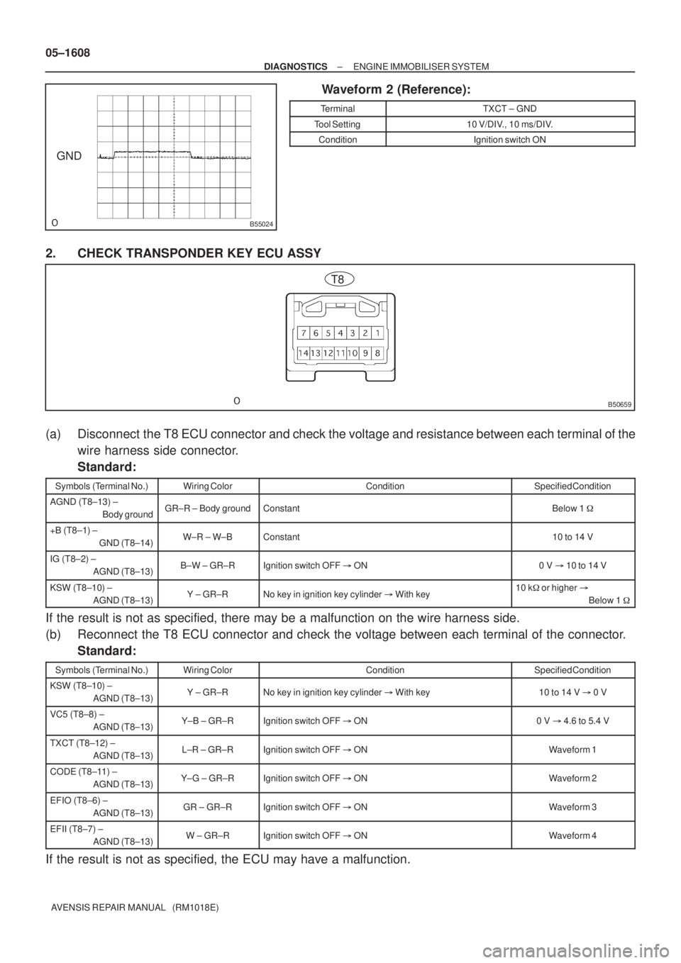
Waveform 2 (Reference):
TerminalTXCT ± GND
Tool Setting10 V/DIV., 10 ms/DIV.
ConditionIgnition switch ON
2. CHECK TRANSPONDER KEY ECU ASSY
(a) Disconnect the T8 ECU connector and check the voltage and resistance between each terminal of the
wire harness side connector.
Standard:
Symbols (Terminal No.)Wiring ColorConditionSpecified Condition
AGND (T8±13) ±
Body groundGR±R ± Body groundConstantBelow 1 �
+B (T8±1) ±
GND (T8±14)W±R ± W±BConstant10 to 14 V
IG (T8±2) ±
AGND (T8±13)B±W ± GR±RIgnition switch OFF �ON0 V �10 to 14 V
KSW (T8±10) ±
AGND (T8±13)Y ± GR±RNo key in ignition key cylinder � With key10 k� or higher�
Below 1 �
If the result is not as specified, there may be a malfunction on the wire harness side.
(b) Reconnect the T8 ECU connector and check the voltage between each terminal of the connector.
Standard:
Symbols (Terminal No.)Wiring ColorConditionSpecified Condition
KSW (T8±10) ±
AGND (T8±13)Y ± GR±RNo key in ignition key cylinder � With key10 to 14 V �0 V
VC5 (T8±8) ±
AGND (T8±13)Y±B ± GR±RIgnition switch OFF �ON0 V �4.6 to 5.4 V
TXCT (T8±12) ±
AGND (T8±13)L±R ± GR±RIgnition switch OFF �ONWaveform 1
CODE (T8±11) ±
AGND (T8±13)Y±G ± GR±RIgnition switch OFF �ONWaveform 2
EFIO (T8±6) ±
AGND (T8±13)GR ± GR±RIgnition switch OFF �ONWaveform 3
EFII (T8±7) ±
AGND (T8±13)W ± GR±RIgnition switch OFF �ONWaveform 4
If the result is not as specified, the ECU may have a malfunction.
Page 1635 of 5135
B66228
E10E12E13E9
B50745
E11E12E13E9E10
05±1610
± DIAGNOSTICSENGINE IMMOBILISER SYSTEM
AVENSIS REPAIR MANUAL (RM1018E)
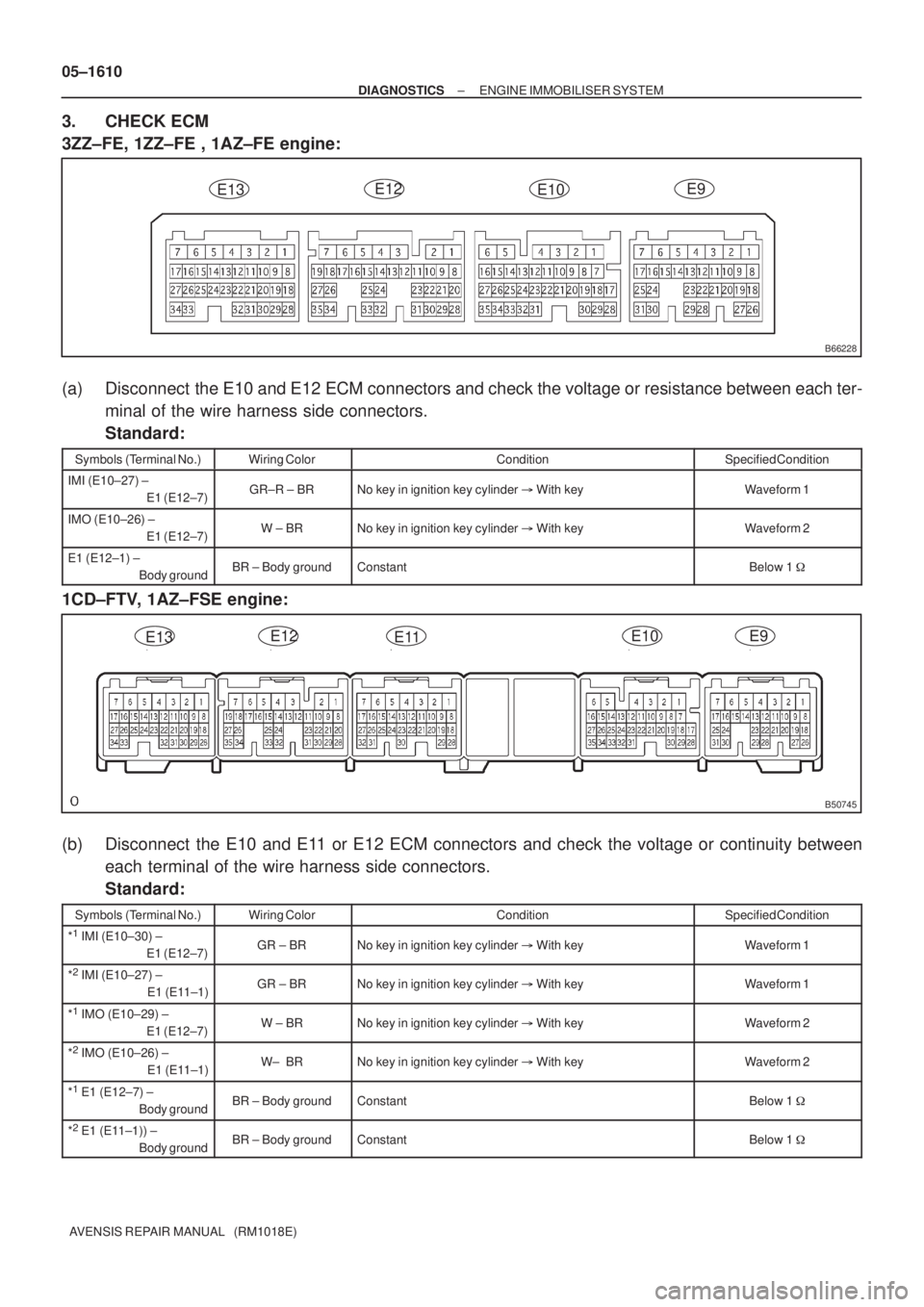
3. CHECK ECM
3ZZ±FE, 1ZZ±FE , 1AZ±FE engine:
(a) Disconnect the E10 and E12 ECM connectors and check the voltage or resistance between each ter-
minal of the wire harness side connectors.
Standard:
Symbols (Terminal No.)Wiring ColorConditionSpecified Condition
IMI (E10±27) ±
E1 (E12±7)GR±R ± BRNo key in ignition key cylinder � With keyWaveform 1
IMO (E10±26) ±
E1 (E12±7)W ± BRNo key in ignition key cylinder � With keyWaveform 2
E1 (E12±1) ±
Body groundBR ± Body groundConstantBelow 1 �
1CD±FTV, 1AZ±FSE engine:
(b) Disconnect the E10 and E11 or E12 ECM connectors and check the voltage or continuity between
each terminal of the wire harness side connectors.
Standard:
Symbols (Terminal No.)Wiring ColorConditionSpecified Condition
*1 IMI (E10±30) ±
E1 (E12±7)GR ± BRNo key in ignition key cylinder � With keyWaveform 1
*2 IMI (E10±27) ±
E1 (E11±1)GR ± BRNo key in ignition key cylinder � With keyWaveform 1
*1 IMO (E10±29) ±
E1 (E12±7)W ± BRNo key in ignition key cylinder � With keyWaveform 2
*2 IMO (E10±26) ±
E1 (E11±1)W± BRNo key in ignition key cylinder � With keyWaveform 2
*1 E1 (E12±7) ±
Body groundBR ± Body groundConstantBelow 1 �
*2 E1 (E11±1)) ±
Body groundBR ± Body groundConstantBelow 1 �
Page 1645 of 5135
B68159
17
DB
DCTY
KSW R B J/C
Combination Meter Assy
IC119
I14 11 DA Y
I14 22
P±B 12 1
W±B*
3
A1310
29*6
Buzzer
Meter ECU
20*
7
U1
Unlock Warning
Switch AssyIntegration Relay
B D9*
4
D10*5
Door Courtesy Lamp Switch
(Driver Side)
W±B
IC1
P
*
1: 1AZ±FSE
*2: 1AZ±FE, 1ZZ±FE, 3ZZ±FE
*
3: 1CD±FTV
*
4: LHD
*5: RHD
*
6: Except Automatic A/C
*7: Automatic A/CMPX2 Instrument Panel J/B
13
J10 J10CE CA1
5
R RIC2 IM1914
8 W±B*
5CF CA13
6
MPX1 P±B
C1014 1
A15
MPX±
MPX+
A13
A159*
6
10*7
P
P±B A/C Control
Assembly
E10 E9 E9212929
E10 E9 E9 202318ECM
*
1*1*2*3*2*3
*5*4
R*5
R*4
Center J/B
Center J/B
C10 13
PR
IPIL W±B*
4A
AJ16
IO W±B*
1,
2
R*5
W±B*5
05±1594
± DIAGNOSTICSKEY REMINDER WARNING SYSTEM
AVENSIS REPAIR MANUAL (RM1018E)
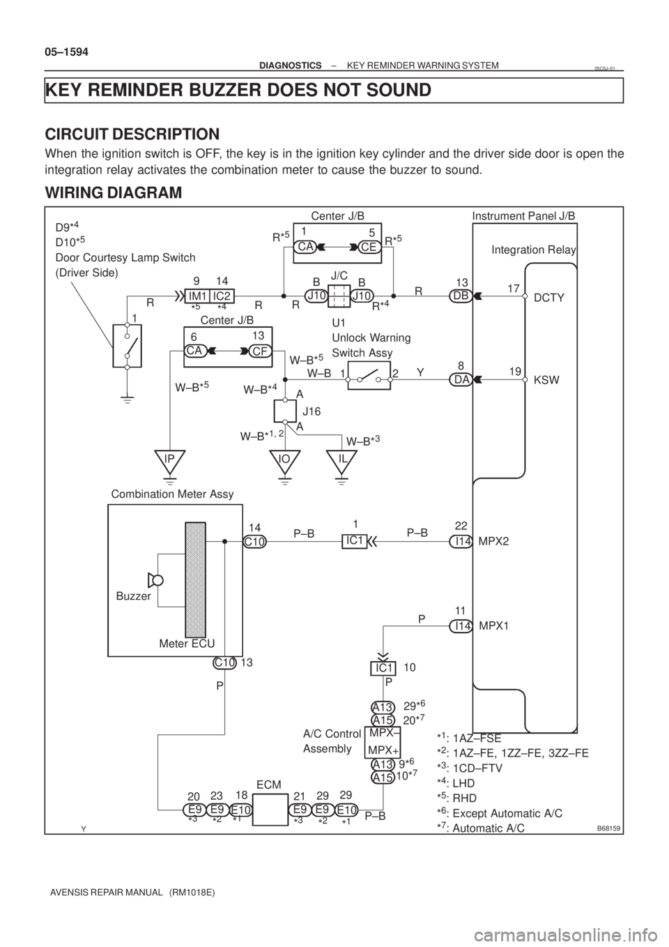
KEY REMINDER BUZZER DOES NOT SOUND
CIRCUIT DESCRIPTION
When the ignition switch is OFF, the key is in the ignition key cylinder and the driver side door is open the
integration relay activates the combination meter to cause the buzzer to sound.
WIRING DIAGRAM
05C5J±01
Page 1652 of 5135
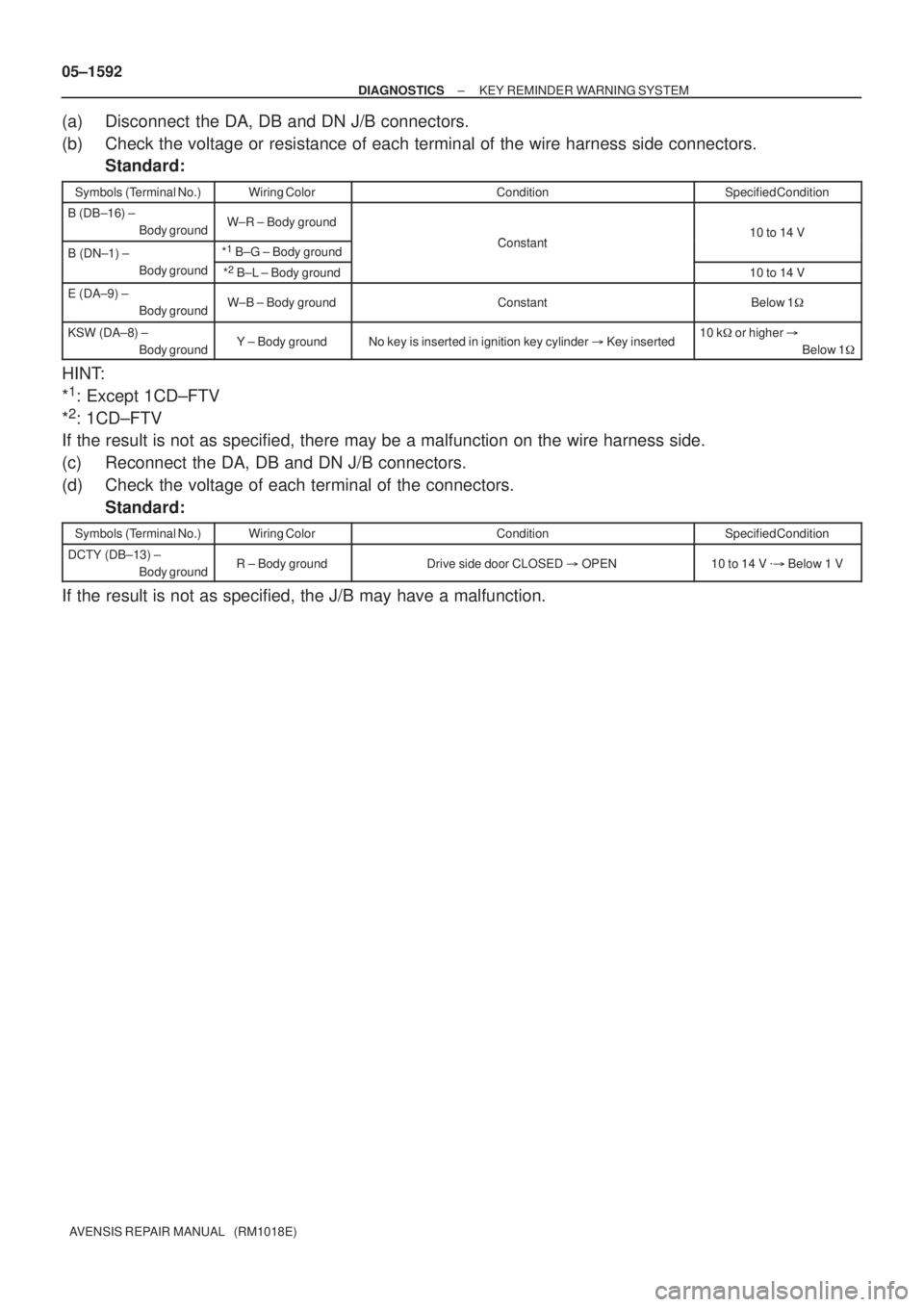
05±1592
± DIAGNOSTICSKEY REMINDER WARNING SYSTEM
AVENSIS REPAIR MANUAL (RM1018E)
(a) Disconnect the DA, DB and DN J/B connectors.
(b) Check the voltage or resistance of each terminal of the wire harness side connectors.
Standard:
Symbols (Terminal No.)Wiring ColorConditionSpecified Condition
B (DB±16) ±
Body groundW±R ± Body ground
Constant10 to 14 V
B (DN±1) ± *1
B±G ± Body groundConstant10 to 14 V
B (DN 1)
Body ground
*2
B±L ± Body ground10 to 14 V
E (DA±9) ±
Body groundW±B ± Body groundConstantBelow 1�
KSW (DA±8) ±
Body groundY ± Body groundNo key is inserted in ignition key cylinder � Key inserted10 k�or higher �
Below 1�
HINT:
*
1: Except 1CD±FTV
*
2: 1CD±FTV
If the result is not as specified, there may be a malfunction on the wire harness side.
(c) Reconnect the DA, DB and DN J/B connectors.
(d) Check the voltage of each terminal of the connectors.
Standard:
Symbols (Terminal No.)Wiring ColorConditionSpecified Condition
DCTY (DB±13) ±
Body groundR ± Body groundDrive side door CLOSED � OPEN10 to 14 V �� Below 1 V
If the result is not as specified, the J/B may have a malfunction.
Page 1658 of 5135
B66772
Instrument Panel J/B Assy
Integration
Relay
FRLY 6
I14 LG
J11D15 T10
Turn Signal Flasher Relay
EHW8
To
Hazard Warning
Signal SwitchIC2
J25
*
1*2
J10 J24
*1*2
J10 J24
*
1*2
LG
LG
LGDDF
FB
*
1: LHD Models
*
2: RHD Models J/C 05±1584
± DIAGNOSTICSWIRELESS DOOR LOCK CONTROL SYSTEM
AVENSIS REPAIR MANUAL (RM1018E)
NO ANSWER±BACK (HAZARD WARNING LAMP)
CIRCUIT DESCRIPTION
If there is no answer±back of the hazard warning lamps although the wireless door lock/unlock function is
operating normally, there might be a malfunction in the hazard warning lamp signal that is output from the
integration relay.
WIRING DIAGRAM
05BNC±01
Page 1660 of 5135
B67694
IG
10 CK CA
Instrument Panel J/B AssyR±W
1 21
3
IG1 AM1
Battery B*
2
G±R
DH1
AM1T6
Theft Warning ECU Assy
Center J/B Assy
7
R±W
I13
Ignition Switch
Assy1G±Y
Main 3 3
4D 4BB±G*
1B±G*1
W*2
1 DA9
1 5 3 GAUGE1
IG1
Relay
ED1 DN DH 5 1DB
7
ALT
ALT Engine Room R/B No. 3
*
1: Gasoline
*2: 1CD±FTV1 B±L*
2
IJ W±B
21
21 Engine Room J/B No. 4
± DIAGNOSTICSTHEFT DETERRENT SYSTEM
05±1639
AVENSIS REPAIR MANUAL (RM1018E)
IGNITION SWITCH CIRCUIT
CIRCUIT DESCRIPTION
When the ignition switch is turned to the ON position, battery positive voltage is applied to terminal IG of the
theft warning ECU.
WIRING DIAGRAM
05BAD±01
Page 1663 of 5135
B67693
+B1
E W±R B±W
1A5
3DCCEngine Room R/B 1IP1
B*
2
BatteryJ/C
IPW±B
29 Center J/B 6T6
Theft Warning ECU Assy
CG 6J26 W±R
J27 6 Fuse Block
DOME
B±W
34A
4B B±G*
1
B±G*1B*2
3.0W Engine
Room R/B
No. 3CA W±B9
*
1: Gasoline
*2: 1CD±FTV 2 1
1 2
1
1FH
2
Engine
Room J/B
No. 4
± DIAGNOSTICSTHEFT DETERRENT SYSTEM
05±1637
AVENSIS REPAIR MANUAL (RM1018E)
ECU POWER SOURCE CIRCUIT
CIRCUIT DESCRIPTION
This circuit provides power to operate the theft warning ECU.
WIRING DIAGRAM
05BAC±01