Page 1501 of 5135

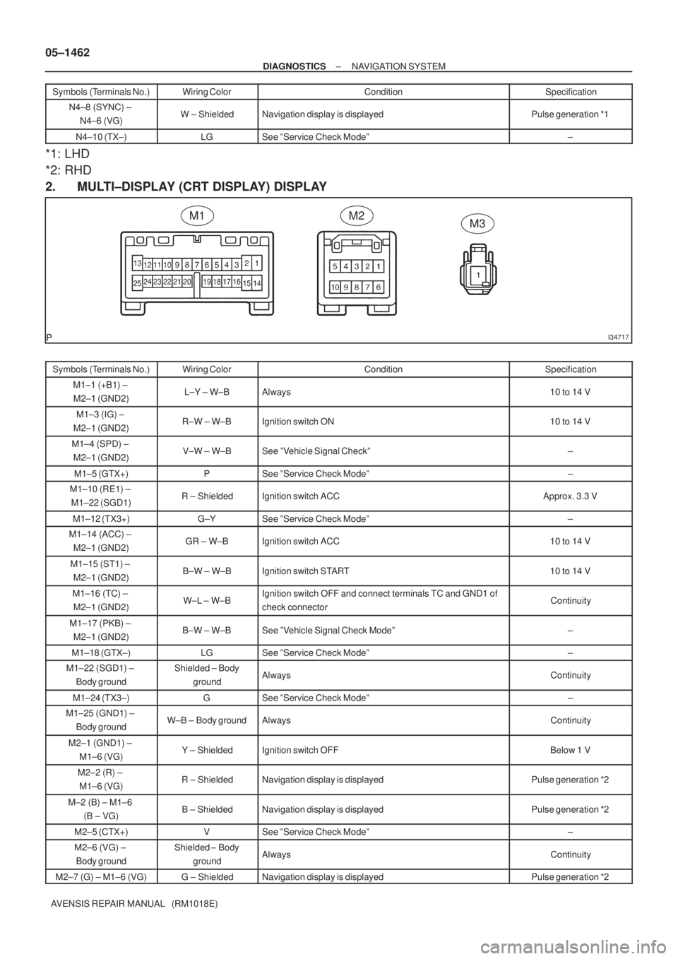
I34717
M1M2M3 05±1462
± DIAGNOSTICSNAVIGATION SYSTEM
AVENSIS REPAIR MANUAL (RM1018E)Symbols (Terminals No.)Specification Condition Wiring Color
N4±8 (SYNC) ±
N4±6 (VG)W ± ShieldedNavigation display is displayedPulse generation *1
N4±10 (TX±)LGSee ºService Check Modeº±
*1: LHD
*2: RHD
2. MULTI±DISPLAY (CRT DISPLAY) DISPLAY
Symbols (Terminals No.)Wiring ColorConditionSpecification
M1±1 (+B1) ±
M2±1 (GND2)L±Y ± W±BAlways10 to 14 V
M1±3 (IG) ±
M2±1 (GND2)R±W ± W±BIgnition switch ON10 to 14 V
M1±4 (SPD) ±
M2±1 (GND2)V±W ± W±BSee ºVehicle Signal Checkº±
M1±5 (GTX+)PSee ºService Check Modeº±
M1±10 (RE1) ±
M1±22 (SGD1)R ± ShieldedIgnition switch ACCApprox. 3.3 V
M1±12 (TX3+)G±YSee ºService Check Modeº±
M1±14 (ACC) ±
M2±1 (GND2)GR ± W±BIgnition switch ACC10 to 14 V
M1±15 (ST1) ±
M2±1 (GND2)B±W ± W±BIgnition switch START10 to 14 V
M1±16 (TC) ±
M2±1 (GND2)W±L ± W±BIgnition switch OFF and connect terminals TC and GND1 of
check connectorContinuity
M1±17 (PKB) ±
M2±1 (GND2)B±W ± W±BSee ºVehicle Signal Check Modeº±
M1±18 (GTX±)LGSee ºService Check Modeº±
M1±22 (SGD1) ±
Body groundShielded ± Body
groundAlwaysContinuity
M1±24 (TX3±)GSee ºService Check Modeº±
M1±25 (GND1) ±
Body groundW±B ± Body groundAlwaysContinuity
M2±1 (GND1) ±
M1±6 (VG)Y ± ShieldedIgnition switch OFFBelow 1 V
M2±2 (R) ±
M1±6 (VG)R ± ShieldedNavigation display is displayedPulse generation *2
M±2 (B) ± M1±6
(B ± VG)B ± ShieldedNavigation display is displayedPulse generation *2
M2±5 (CTX+)VSee ºService Check Modeº±
M2±6 (VG) ±
Body groundShielded ± Body
groundAlwaysContinuity
M2±7 (G) ± M1±6 (VG)G ± ShieldedNavigation display is displayedPulse generation *2
Page 1502 of 5135
I35656
C10
I30915
I30916
± DIAGNOSTICSNAVIGATION SYSTEM
05±1463
AVENSIS REPAIR MANUAL (RM1018E)Symbols (Terminals No.)Specification Condition Wiring Color
M2±8 (SYNC) ±
M1±6 (VG)W ± ShieldedNavigation display is displayedPulse generation *1
M2±10 (CTX±)LGSee ºService Check Modeº±
M3±1 (GND2) ±
Body groundW±B ± Body groundAlwaysContinuity
3. BODY ECU (COMBINATION METER ASSY)
Symbols (Terminals No.)Wiring ColorConditionSpecification
C10±3 (GTX+)G±YSee ºService Check Modeº±
C10±4 (GTX±)GSee ºService Check Modeº±
(a) *1: Oscilloscope wave
Terminal to be measured: SYNC ± GND
Setting for measurement: 500 mV/DIV10± �s/DIV
Condition: Navigation display is displayed.
(b) *2: Oscilloscope wave
Terminal to be measured: R, G, B ± GND
Setting for measurement: 200 mV/DIV10± �s/DIV
Condition: Navigation map is switched.
Page 1527 of 5135

05C4G±01
I35933
C10 C11
05±1506
± DIAGNOSTICSCOMBINATION METER
AVENSIS REPAIR MANUAL (RM1018E)
TERMINALS OF ECU
COMBINATION METER ASSY
Terminal No.Wiring colorConditionSpecified condition
C11±1 ± Body ground
(TURN L ± Body ground)G±W ± Body
groundTurn signal LH indicator light OFF � ONBelow 1 V �
10 to 14 V
C11±2 ± Body ground
(BRAKE LVL SW ±
Body ground)R±W ± Body
groundBrake fluid level warning switch ONBelow 1 V
C11±3 ± Body ground
(TACHO ± Body ground)GR±R ± Body
groundIgnition switch OFF � ON, Engine idle speedPuls generation (*2)
C11±5 ± Body ground
(SIGNAL EARTH ±
Body ground)W±B ± Body
groundConstantContinuity
C11±6 ± Body ground
(EMPS ± Body ground)B±W ± Body
groundIgnition switch ON and EMPS Indicator OFF � ON10 to 14 V �
Below 1 V
C11±8 ± Body ground
(AIRBAG ± Body ground)B±Y ± Body
groundIgnition switch ON and AIRBAG Indicator OFF � ON10 to 14 V �
Below 1 V
C11±9 ± Body ground
(CHECK ENGINE ±
Body ground)
W ± Body groundEngine running and CHECK ENGINE indicator OFF9 to 14 V
C11±10 ± Body ground
(AUTO LEVELING ±
Body ground)LG ± Body
groundIgnition switch ON and AUTO LEVERING Indicator OFF � ON10 to 14 V �
Below 1 V
C11±11 ± Body ground
(OIL PRESS SW ±
Body ground)Y±B ± Body
groundEngine running�StoppedNo continuity �
Continuity
C11±12 ± Body ground
(BEAM+ ± Body ground)R±W (w/HID),
R (w/o HID) ±
Body ground
Headlight OFF�ONBelow 1 V �
10 to 14 V
C11±13 ± Body ground
(TURN R ± Body ground)G±Y ± Body
groundTurn signal RH indicator light OFF � ONBelow 1 V �
10 to 14 V
C11±14 ± Body ground
(ILL+ ± Body ground)G ± Body groundCombination switch OFF�ONBelow 1 V �
10 to 14 V
C11±15 ± Body ground
(SLIP ± Body ground)LG ± Body
groundIgnition switch ON and SLIP Indicator OFF � ON10 to 14 V �
Below 1 V
C11±16 ± Body ground
(VSC ± Body ground)W±R ± Body
groundIgnition switch ON and VSC Indicator OFF � ON10 to 14 V �
Below 1 V
Page 1539 of 5135
I35657
S15
Steering Pad Switch LH
Multi±display
(CRT Display) DisplayAU1
AU2
EAU12
11
10LG (*1)
P (*1)
W±R (*1)
GTX+
GTX±
CTX±
CTX+M1
M1
M2
M25
18
10
5P
LG
LG
V
T11
Telephone Microphone Assy
MACC
MIC+
MIC±5
4
2R
B
W
(Shielded)17
ID1
ID1
ID1
ID118
16
14R
B
W
(Shielded)Radio Receiver Assy
7
8
6 R7
R7
R7SW1
SW2
GND
TX+
TX± R6
R69
10
Navigation ECU
TX±
TX+
MACC
MIC+
MIC±
SGND N4
N4
N5
N5
N5
N54
3
5
6 BR
BR
*1: w/ Steering SW10
5 05±1494
± DIAGNOSTICSNAVIGATION SYSTEM
AVENSIS REPAIR MANUAL (RM1018E)
THE SYSTEM CANNOT BE OPERATED BY THE VOICE SOUND
WIRING DIAGRAM
05C3W±01
Page 1542 of 5135
I34721
R11
Navigation Controller Holder
(Shielded)Multi±display
(CRT Display) Display
TX
SGND3
2R
(Shielded)10
22 M1
M1RE1
SGD1
I35661
05±1492
± DIAGNOSTICSNAVIGATION SYSTEM
AVENSIS REPAIR MANUAL (RM1018E)
WHEN MOUNT THE NAVIGATION CONTROLLER ASSY TO THE
NAVIGATION CONTROLLER HOLDER, IT CANNOT BE OPERATED
WIRING DIAGRAM
INSPECTION PROCEDURE
1 CLEAN THE INFRARED RAY EMITTED PORTION
(a) Clean the infrared ray emitted portion.
(1) Clean the infrared ray emitted portion on the navi-
gation controller holder and navigation controller
assy.
(2) Check whether the same malfunction occurs.
Standard: The function returns to normal.
OK DIRT AT THE INFRARED RAY EMITTED
PORTION
NG
05C3V±01
Page 1545 of 5135

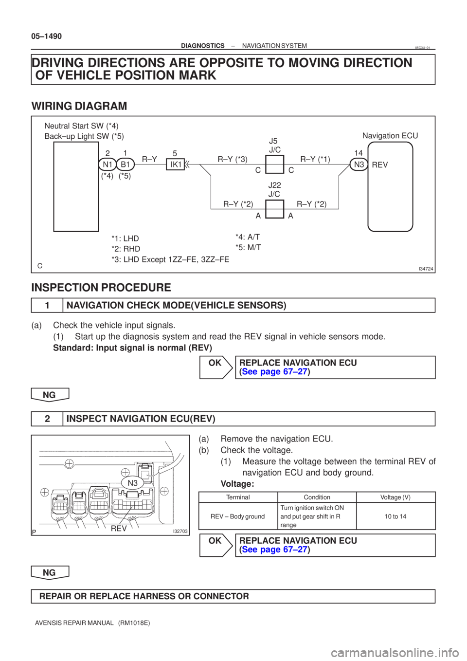
I34724
Neutral Start SW (*4)
Back±up Light SW (*5)21
N1B1
(*4)(*5) 5
IK1
R±YR±Y (*3)R±Y (*1)
R±Y (*2)R±Y (*2)AA
CC
J5
J/C
J22
J/C 14
N3
Navigation ECU
REV
*1: LHD
*2: RHD
*3: LHD Except 1ZZ±FE, 3ZZ±FE *4: A/T
*5: M/T
I32703REV
N3
05±1490
±
DIAGNOSTICS NAVIGATION SYSTEM
AVENSIS REPAIR MANUAL (RM1018E)
DRIVING DIRECTIONS ARE OPPOSITE TO MOVING DIRECTION OF VEHICLE POSITION MARK
WIRING DIAGRAM
INSPECTION PROCEDURE
1NAVIGATION CHECK MODE(VEHICLE SENSORS)
(a)Check the vehicle input signals.
(1)Start up the diagnosis system and read the REV signal in vehicle sensors\
mode.
Standard: Input signal is normal (REV)
OKREPLACE NAVIGATION ECU (See page 67±27)
NG
2INSPECT NAVIGATION ECU(REV)
(a)Remove the navigation ECU.
(b)Check the voltage. (1)Measure the voltage between the terminal REV ofnavigation ECU and body ground.
Voltage:
TerminalConditionVoltage (V)
REV ±Body ground
Turn ignition switch ON
and put gear shift in R
range
10 to 14
OKREPLACE NAVIGATION ECU (See page 67±27)
NG
REPAIR OR REPLACE HARNESS OR CONNECTOR
05C3U±01
Page 1546 of 5135

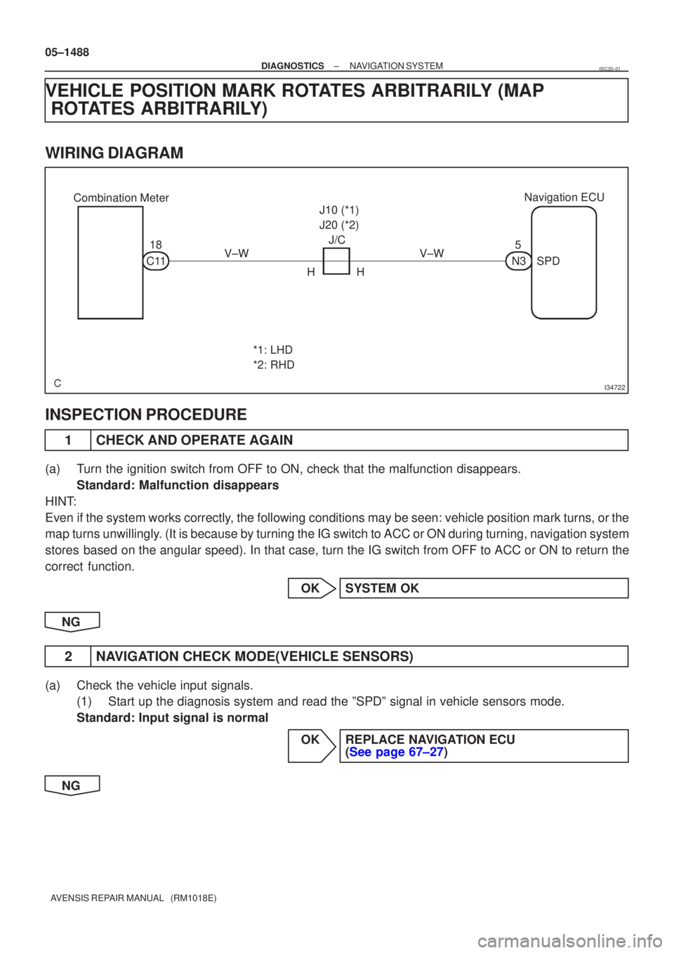
I34722
Combination MeterNavigation ECU
18
C11 V±W J/C
HH J10 (*1)
J20 (*2)
V±W
*1: LHD
*2: RHD 5
N3SPD
05±1488
±
DIAGNOSTICS NAVIGATION SYSTEM
AVENSIS REPAIR MANUAL (RM1018E)
VEHICLE POSITION MARK ROTATES ARBITRARILY (MAP ROTATES ARBITRARILY)
WIRING DIAGRAM
INSPECTION PROCEDURE
1CHECK AND OPERATE AGAIN
(a)Turn the ignition switch from OFF to ON, check that the malfunction disappea\
rs.
Standard: Malfunction disappears
HINT:
Even if the system works correctly, the following conditions may be seen: vehicle position mark turns, or the
map turns unwillingly. (It is because by turning the IG switch to ACC or ON during turning, \
navigation system
stores based on the angular speed). In that case, turn the IG switch from OFF to ACC\
or ON to return the
correct function.
OKSYSTEM OK
NG
2NAVIGATION CHECK MODE(VEHICLE SENSORS)
(a)Check the vehicle input signals. (1)Start up the diagnosis system and read the ºSPDº signal in vehicle\
sensors mode.
Standard: Input signal is normal
OKREPLACE NAVIGATION ECU (See page 67±27)
NG
05C3S±01
Page 1553 of 5135
I34726
Radio Receiver Assy
FL±
FL+
FR±
FR+6
12
5 R4
R4
R4
R4LG (*1)
R (*1)
R (*2)
W (*2)Navigation ECU
10
N3
N31AUI±
AUI+
11
N3
N32AUO±
AUO+ F21
Front No.1
Speaker Assy LH
F22
Front No.1
Speaker Assy RH2
1
LG1 LT16
Tweeter Front LH
(±) IN
(+) OUT(+) IN (±) OUT
2
34V
P6
IA1
IA1
IL1
IL1V (*1)
P (*1)
2
1
P1 VT17
Tweeter Front RH
(±) IN
(+) OUT(+) IN (±) OUT
2
34LGL61
1
LG (*2) L (*2)
*1: LHD
*2: RHD
± DIAGNOSTICSNAVIGATION SYSTEM
05±1479
AVENSIS REPAIR MANUAL (RM1018E)
FRONT SPEAKER (DRIVER SIDE) ONLY IS NOT HEARD
WIRING DIAGRAM
05C3N±01