Page 1400 of 5135
�����
\b�����
����
����
H41469
Curtain Shield
Squib LH
Airbag
Sensor
Assy
Center
Floor Wire
A
B
C
D
05±1340
±
DIAGNOSTICS SUPPLEMENTAL RESTRAINT SYSTEM
AVENSIS REPAIR MANUAL (RM1018E)
DTC B1167/85 SHORT IN CURTAIN SHIELD SQUIB (LH) CIRCUIT (TO GROUND)
CIRCUIT DESCRIPTION
The curtain shield squib LH circuit consists of the airbag sensor assy cent\
er and the curtain shield airbag
assy LH.
This circuit actuates the SRS to deploy when the SRS deployment conditio\
ns are fulfilled.
DTC B1167/85 is recorded when a short to ground is detected in the curtain shi\
eld squib LH circuit.
DTC No.DTC Detecting ConditionTrouble Area
B1167/85
�Short circuit in curtain shield squib LH wire harness
(to ground)
� Curtain shield squib LH malfunction
� Airbag sensor assy malfunction�Curtain shield airbag assy LH (Curtain Shield Squib LH)
� Airbag sensor assy center
� Floor wire
HINT:
DTC B1167/85 is indicated only for the vehicle equipped with the curtain shiel\
d airbag.
WIRING DIAGRAM
See page 05±1334.
INSPECTION PROCEDURE
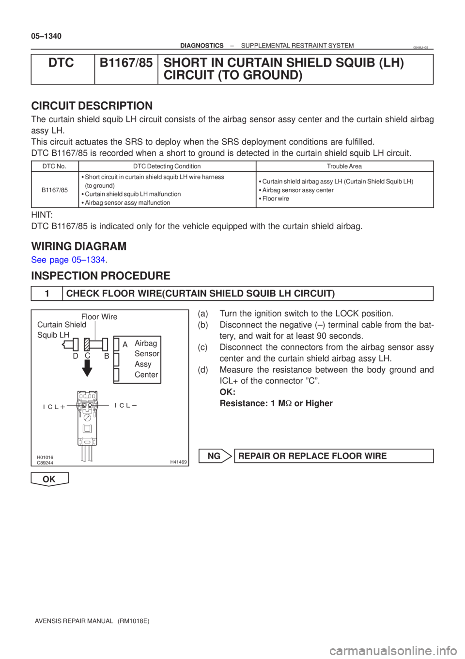
1 CHECK FLOOR WIRE(CURTAIN SHIELD SQUIB LH CIRCUIT)
(a) Turn the ignition switch to the LOCK position.
(b) Disconnect the negative (±) terminal cable from the bat-
tery, and wait for at least 90 seconds.
(c) Disconnect the connectors from the airbag sensor assy center and the curtain shield airbag assy LH.
(d) Measure the resistance between the body ground and ICL+ of the connector ºCº.
OK:
Resistance: 1 M � or Higher
NG REPAIR OR REPLACE FLOOR WIRE
OK
054MJ±05
Page 1403 of 5135
�����
\b�����
����
����
H41469
Curtain Shield
Squib LH
Airbag
Sensor
Assy
Center
Floor Wire
A
B
C
D
±
DIAGNOSTICS SUPPLEMENTAL RESTRAINT SYSTEM
05±1337
AVENSIS REPAIR MANUAL (RM1018E)
DTC B1166/88 OPEN IN CURTAIN SHIELD SQUIB (LH)
CIRCUIT
CIRCUIT DESCRIPTION
The curtain shield squib LH circuit consists of the airbag sensor assy cent\
er and the curtain shield airbag
assy LH.
This circuit actuates the SRS to deploy when the SRS deployment conditio\
ns are fulfilled.
DTC B1166/88 is recorded when an open circuit is detected in the curtain shiel\
d squib LH circuit.
DTC No.DTC Detecting ConditionTrouble Area
B1166/88
�Open circuit in ICL+ wire harness or ICL± wire harness of
curtain shield squib LH
� Curtain shield squib LH malfunction
� Airbag sensor assy center malfunction�Curtain shield airbag assy LH (Curtain shield squib LH)
� Airbag sensor assy center
� Floor wire
HINT:
DTC B1166/88 is indicated only for the vehicle equipped with the curtain shiel\
d airbag.
WIRING DIAGRAM
See page 05±1184.
INSPECTION PROCEDURE
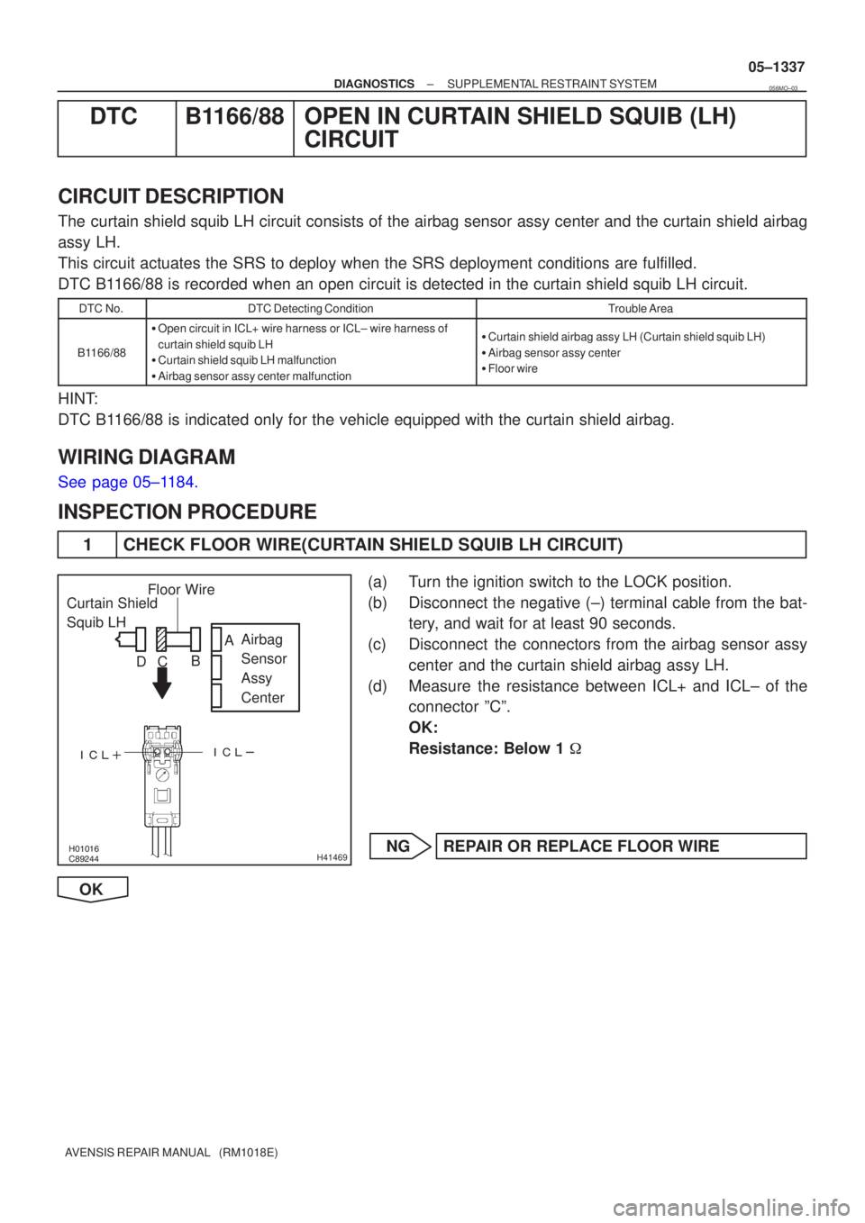
1 CHECK FLOOR WIRE(CURTAIN SHIELD SQUIB LH CIRCUIT)
(a) Turn the ignition switch to the LOCK position.
(b) Disconnect the negative (±) terminal cable from the bat-
tery, and wait for at least 90 seconds.
(c) Disconnect the connectors from the airbag sensor assy center and the curtain shield airbag assy LH.
(d) Measure the resistance between ICL+ and ICL± of the connector ºCº.
OK:
Resistance: Below 1 �
NG REPAIR OR REPLACE FLOOR WIRE
OK
056MO±03
Page 1406 of 5135
H01454
C17
Curtain Shield Squib LHAirbag Sensor Assy Center
1
2Y±V
Y±RA26
A269
10ICL+
ICL± (*1)
(*1)
*1: w/ Curtain Shield Airbag 05±1334
± DIAGNOSTICSSUPPLEMENTAL RESTRAINT SYSTEM
AVENSIS REPAIR MANUAL (RM1018E)
DTC B1165/87 SHORT IN CURTAIN SHIELD SQUIB (LH)
CIRCUIT
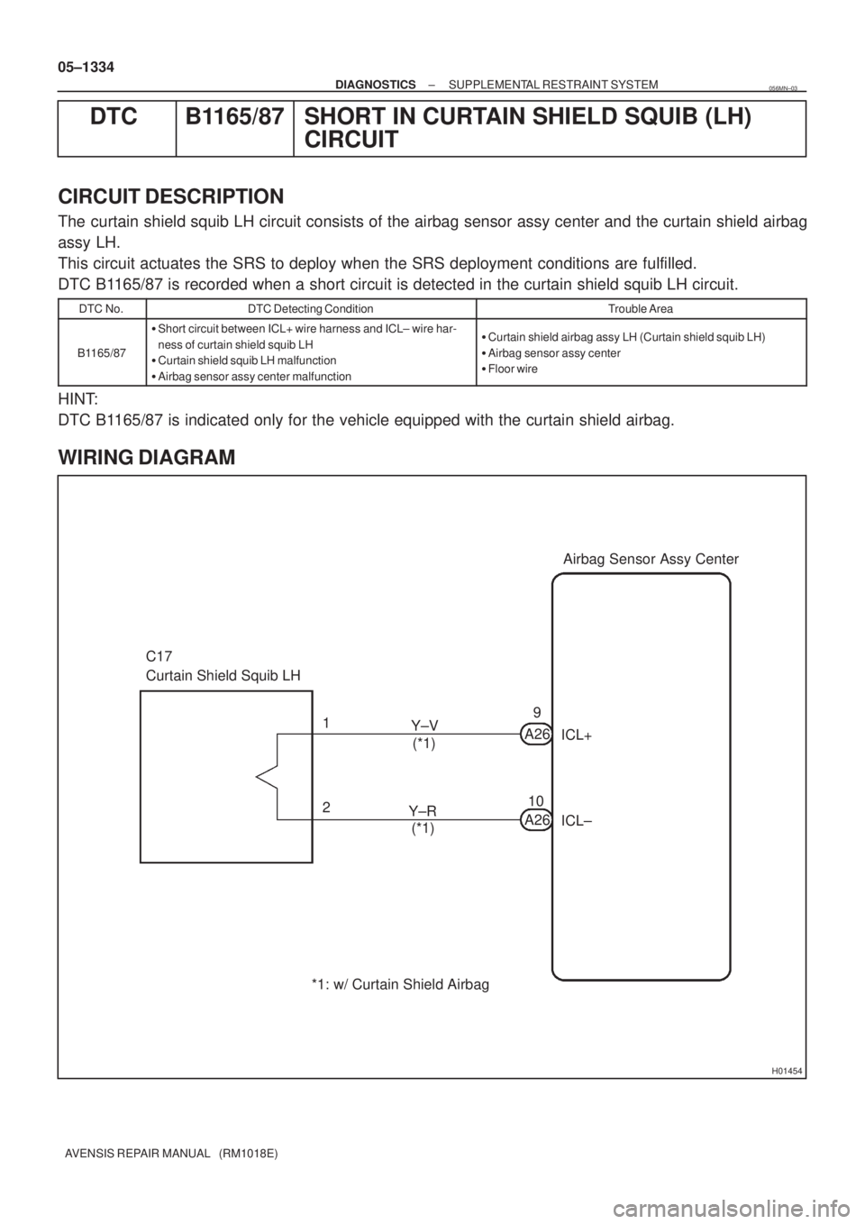
CIRCUIT DESCRIPTION
The curtain shield squib LH circuit consists of the airbag sensor assy center and the curtain shield airbag
assy LH.
This circuit actuates the SRS to deploy when the SRS deployment conditions are fulfilled.
DTC B1165/87 is recorded when a short circuit is detected in the curtain shield squib LH circuit.
DTC No.DTC Detecting ConditionTrouble Area
B1165/87
�Short circuit between ICL+ wire harness and ICL± wire har-
ness of curtain shield squib LH
�Curtain shield squib LH malfunction
�Airbag sensor assy center malfunction�Curtain shield airbag assy LH (Curtain shield squib LH)
�Airbag sensor assy center
�Floor wire
HINT:
DTC B1165/87 is indicated only for the vehicle equipped with the curtain shield airbag.
WIRING DIAGRAM
056MN±03
Page 1409 of 5135
\b�����
������
����
����
H41465
Curtain Shield
Squib RH Airbag
Sensor
Assy
Center
Floor Wire No.2
A
B
C
D
±
DIAGNOSTICS SUPPLEMENTAL RESTRAINT SYSTEM
05±1331
AVENSIS REPAIR MANUAL (RM1018E)
DTC B1163/82 SHORT IN CURTAIN SHIELD SQUIB (RH)
CIRCUIT (TO B+)
CIRCUIT DESCRIPTION
The curtain shield squib RH circuit consists of the airbag sensor assy cent\
er and the curtain shield airbag
assy RH.
This circuit actuates the SRS to deploy when the SRS deployment conditio\
ns are fulfilled.
DTC B1163/82 is recorded when a short to B+ is detected in the curtain shield \
squib RH circuit.
DTC No.DTC Detecting ConditionTrouble Area
B1163/82
�Short circuit in curtain shield squib RH wire harness (to B+)
� Curtain shield squib RH malfunction
� Airbag sensor assy center malfunction�Curtain shield airbag assy RH (Curtain shield squib RH)
� Airbag sensor assy center
� Floor wire No.2
HINT:
DTC B1163/82 is indicated only for the vehicle equipped with the curtain shiel\
d airbag.
WIRING DIAGRAM
See page 05±1322.
INSPECTION PROCEDURE
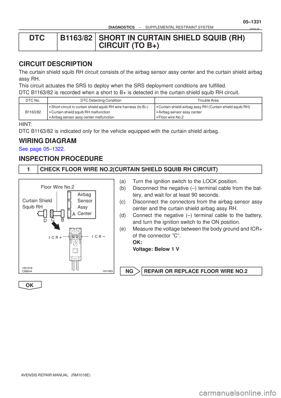
1 CHECK FLOOR WIRE NO.2(CURTAIN SHIELD SQUIB RH CIRCUIT)
(a) Turn the ignition switch to the LOCK position.
(b) Disconnect the negative (±) terminal cable from the bat-
tery, and wait for at least 90 seconds.
(c) Disconnect the connectors from the airbag sensor assy center and the curtain shield airbag assy RH.
(d) Connect the negative (±) terminal cable to the battery, and turn the ignition switch to the ON position.
(e) Measure the voltage between the body ground and ICR+ of the connector ºCº.
OK:
Voltage: Below 1 V
NG REPAIR OR REPLACE FLOOR WIRE NO.2
OK
054MG±05
Page 1412 of 5135
\b�����
������
����
����
H41465
Curtain Shield
Squib RH Airbag
Sensor
Assy
Center
Floor Wire No.2
A
B
C
D
05±1328
±
DIAGNOSTICS SUPPLEMENTAL RESTRAINT SYSTEM
AVENSIS REPAIR MANUAL (RM1018E)
DTC B1162/81 SHORT IN CURTAIN SHIELD SQUIB (RH) CIRCUIT (TO GROUND)
CIRCUIT DESCRIPTION
The curtain shield squib RH circuit consists of the airbag sensor assy cent\
er and the curtain shield airbag
assy RH.
This circuit actuates the SRS to deploy when the SRS deployment conditio\
ns are fulfilled.
DTC B1162/81 is recorded when a short to ground is detected in the curtain shi\
eld squib RH circuit.
DTC No.DTC Detecting ConditionTrouble Area
B1162/81
�Short circuit in curtain shield squib RH wire harness (to
ground)
� Curtain shield squib RH malfunction
� Airbag sensor assy malfunction�Curtain shield airbag assy RH (Curtain shield squib RH)
� Airbag sensor assy center
� Floor wire No.2
HINT:
DTC B1162/81 is indicated only for the vehicle equipped with the curtain shiel\
d airbag.
WIRING DIAGRAM
See page 05±1322.
INSPECTION PROCEDURE
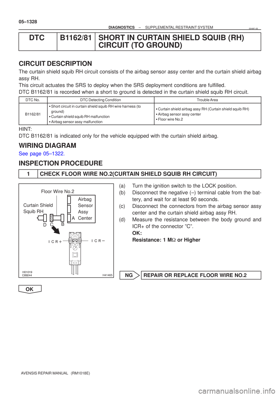
1 CHECK FLOOR WIRE NO.2(CURTAIN SHIELD SQUIB RH CIRCUIT)
(a) Turn the ignition switch to the LOCK position.
(b) Disconnect the negative (±) terminal cable from the bat-
tery, and wait for at least 90 seconds.
(c) Disconnect the connectors from the airbag sensor assy center and the curtain shield airbag assy RH.
(d) Measure the resistance between the body ground and ICR+ of the connector ºCº.
OK:
Resistance: 1 M � or Higher
NG REPAIR OR REPLACE FLOOR WIRE NO.2
OK
054MF±05
Page 1432 of 5135
H43588
Driver Side J/BAirbag Sensor Assy Center
D5 DLC3
TCW−
L
J21D
J/C
(*2) TC
(*2)
W− L
(*1) J20
B
(*2)
J8
B
(*1) W−
L
DB17
DD8
J8 B
(*1) A27
19
13 W−
L
1AZ−
FSE, 1CD− FTV Engine:
CG TC TC
TC
TC
W−
L
W− L
W− L
W−
L
W−B
W−
B
W−
B
W− B
(*1)
(*2) J9 J21
DD
(*2)(*1)
DL DC
15
3
E9
S1
S2
20
17
25
(*2)
A
J16
J/C
A
(*1)
IO IP
(*3)
M1
16
4
CA
CB 3
6
(*6)
(*4, *5)
Skid Control ECU with Actuator Skid Control ECU with Actuator ECM
Multi− Display
*1: LHD *2: RHD
*3: w/ Navigation System (Map Type) *4:
1AZ− FSE
*5: 1CD− FTV (w/ VSC)
*6: 1CD− FTV (w/ ABS)
Center J/B
−
DIAGNOSTICS SUPPLEMENTAL RESTRAINT SYSTEM
05−1391
TC TERMINAL CIRCUIT
CIRCUIT DESCRIPTION
DTC output mode is set by connecting terminals TC and CG of the DLC3.
The DTCs are displayed by blinking the SRS warning light.
WIRING DIAGRAM
05C65 −01
Page 1434 of 5135
H43589
Driver Side J/BAirbag Sensor Assy Center
D5 DLC3
TCW−
L
J8 TC
(*2)
(*1)
W−L
DB 17
DD8
B
(*1) A27
19
*1: LHD B
13
1ZZ−
FE, 3ZZ −FE Engine:
W−L
W−
L
W−L
J8
J9 D
TCTC
TC
CG
W−
B
W− B
W−B W−
B
M116
4
AJ16
J/C
A
IO IP
(*2)
(*1) (*2)
(*1) CA
CB 6
3 J/C
DC
DL 3
15
E920
S2 25 ECM
Skid Control ECU with Actuator Multi−Display
*2: RHD
*3: w/ Navigation System (Map Type) B
B
J20 J20
(*1)
J9D
D
D
J21 J21
(*2)
TC
W−
L
W−
B(*1)
E15 4
W−L(*1) Center J/B
(*2) (*1)(*
1) (*2)
(*3)
W−
L
(*2) W−
L
(*2)
EPS ECU
−
DIAGNOSTICS SUPPLEMENTAL RESTRAINT SYSTEM
05−1392-1
HINT:
When each warning light stays blinking, a ground short in the wiring of terminal TC of the DLC3 or an internal
ground short in each ECU is suspected.
Page 1437 of 5135
± DIAGNOSTICSSUPPLEMENTAL RESTRAINT SYSTEM
05±1389
AVENSIS REPAIR MANUAL (RM1018E)
SRS WARNING LIGHT CIRCUIT MALFUNCTION (DOES NOT LIGHT
UP, WHEN IGNITION SWITCH IS TURNED TO ON)
CIRCUIT DESCRIPTION
The SRS warning light is located on the combination meter assy.
When the SRS is normal, the SRS warning light comes on for approx. 6 seconds after the ignition switch
is turned from the LOCK position to the ON position, and then it turns off automatically.
If there is a malfunction in the SRS, the SRS warning light comes on to inform a trouble to the driver.
When between terminal TC and terminal CG of the DLC3 are connected, the DTC is displayed by blinking
the SRS warning light.
WIRING DIAGRAM
See page .
INSPECTION PROCEDURE
1 CHECK SOURCE VOLTAGE
(a) Measure the voltage of the battery.
OK:
Voltage: 10 to 14 V
NG HARNESS BETWEEN BATTERY AND AIRBAG
SENSOR ASSY CENTER, AND CHARGING
SYSTEM
OK
2 CHECK AIR BAG SENSOR ASSY CENTER
(a) Turn the ignition switch to the LOCK position.
(b) Disconnect the negative (±) terminal cable from the battery, and wait for at least 90 seconds.
(c) Disconnect the connectors from the airbag sensor assy center.
(d) Connect the negative (±) terminal cable to the battery, and turn the ignition switch to the ON position.
(e) Check that the SRS warning light operation.
OK:
The SRS warning light does not come on.
NG REPLACE AIR BAG SENSOR ASSY CENTER
OK
056N4±03