Page 1439 of 5135
H42518
Combination Meter Assy
Driver Side J/BAirbag Sensor Assy Center
*1: LHD
*2: RHD
*3: Gasoline
*4: 1CD±FTV SRS8
C11B±Y
J16
J/C(*2)
IL 17
C1012
DA6
DDB±Y3
A27
LA
W±B
J15
J/C W±B
(*1)
A
AW±B
W±B
(*1, *4)(*1, *3)(*2) W±B
A
A J17
J/C
A
IO
IK 05±1386
± DIAGNOSTICSSUPPLEMENTAL RESTRAINT SYSTEM
AVENSIS REPAIR MANUAL (RM1018E)
SRS WARNING LIGHT CIRCUIT MALFUNCTION (ALWAYS LIGHT
UP, WHEN IGNITION SWITCH IS ACC OR LOCK POSITION)
CIRCUIT DESCRIPTION
The SRS warning light is located on the combination meter assy.
When the SRS is normal, the SRS warning light comes on for approx. 6 seconds after the ignition switch
is turned from the LOCK position to the ON position, and then it turns off automatically.
If there is a malfunction in the SRS, the SRS warning light comes on to inform a trouble to the driver.
When between terminal TC and terminal CG of the DLC3 are connected, the DTC is displayed by blinking
the SRS warning light.
WIRING DIAGRAM
05C64±01
Page 1442 of 5135

H42517
Airbag Sensor Assy Center
A275
E1
E2 27IG2 2
1
Battery28 4IGN Driver Side J/B
IG2
AM2 I13
Ignition SW
B
4 3 6
Engine Room R/B No.1, Engine Room J/B No.1 AM2B±R
DD
W±BB±W
A27
A27 DD DH5
DAW±B 1 11
B±R1
1
1A
2
1 IE4 IP1
(*3)
(*4)(*1) B±G
Engine Room R/B No.3
Engine Room J/B No.43
DD 4B4A
3 9(*1) B±G (*2)
(*1) B±GB
(*2)
Driver Side J/B
IJ FL MAIN
W±B
*1: Gasoline
*2: 1CD±FTV*3: LHD
*4: RHD B±R
± DIAGNOSTICSSUPPLEMENTAL RESTRAINT SYSTEM
05±1383
AVENSIS REPAIR MANUAL (RM1018E)
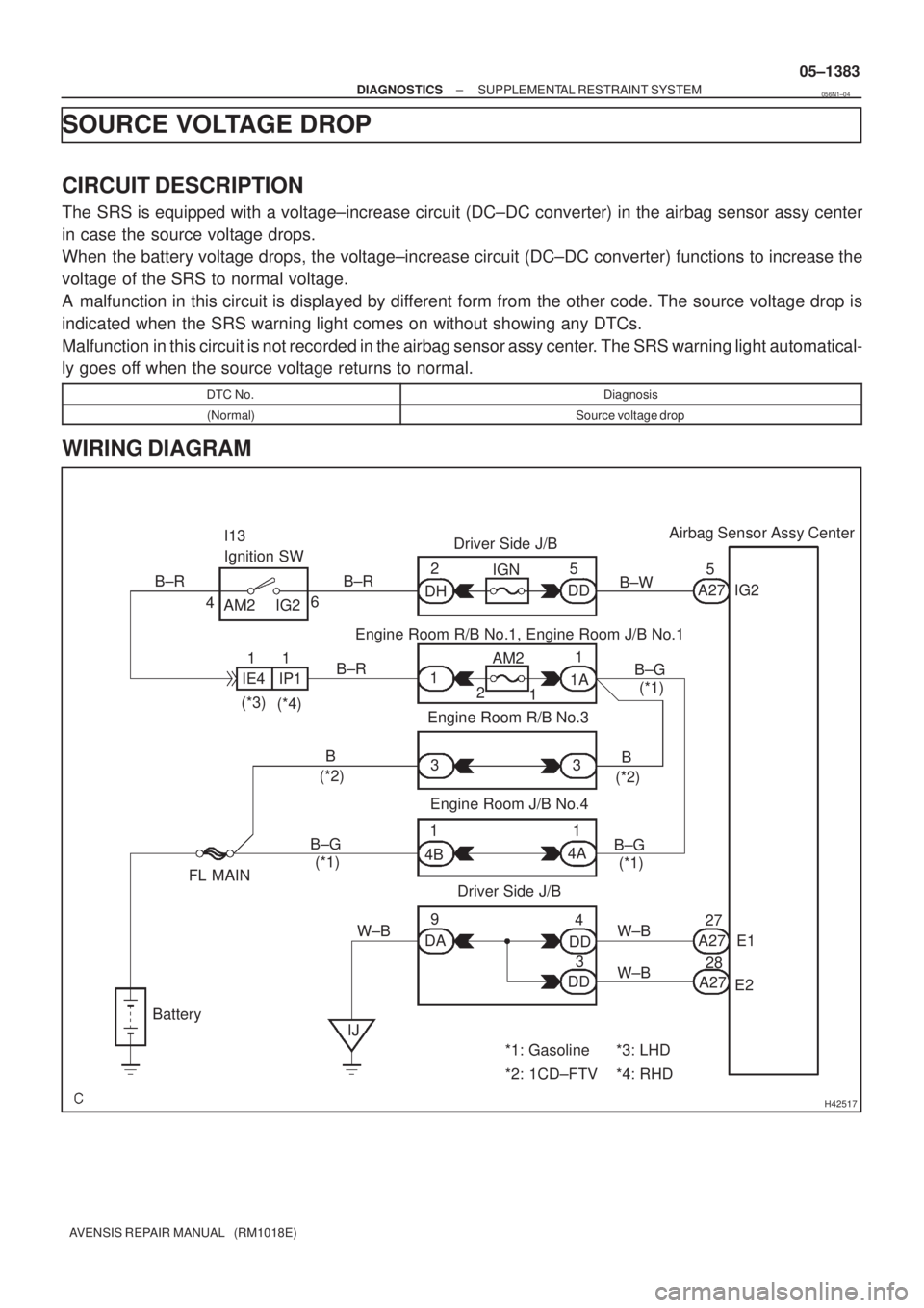
SOURCE VOLTAGE DROP
CIRCUIT DESCRIPTION
The SRS is equipped with a voltage±increase circuit (DC±DC converter) in the airbag sensor assy center
in case the source voltage drops.
When the battery voltage drops, the voltage±increase circuit (DC±DC converter) functions to increase the
voltage of the SRS to normal voltage.
A malfunction in this circuit is displayed by different form from the other code. The source voltage drop is
indicated when the SRS warning light comes on without showing any DTCs.
Malfunction in this circuit is not recorded in the airbag sensor assy center. The SRS warning light automatical-
ly goes off when the source voltage returns to normal.
DTC No.Diagnosis
(Normal)Source voltage drop
WIRING DIAGRAM
056N1±04
Page 1445 of 5135

H42516
K3
Knee Airbag SquibAirbag Sensor Assy Center
Y±R
IN1
2
1A2811
DK±
1 2
A2812
IN1 Y±BY±R
Y±B
DK+ 05±1374
± DIAGNOSTICSSUPPLEMENTAL RESTRAINT SYSTEM
AVENSIS REPAIR MANUAL (RM1018E)
DTC B1650/49 SHORT IN KNEE SQUIB CIRCUIT
DTC B1651/49 OPEN IN KNEE SQUIB CIRCUIT
DTC B1652/49 SHORT IN KNEE SQUIB CIRCUIT (TO
GROUND)
DTC B1653/49 SHORT IN KNEE SQUIB CIRCUIT (TO B+)
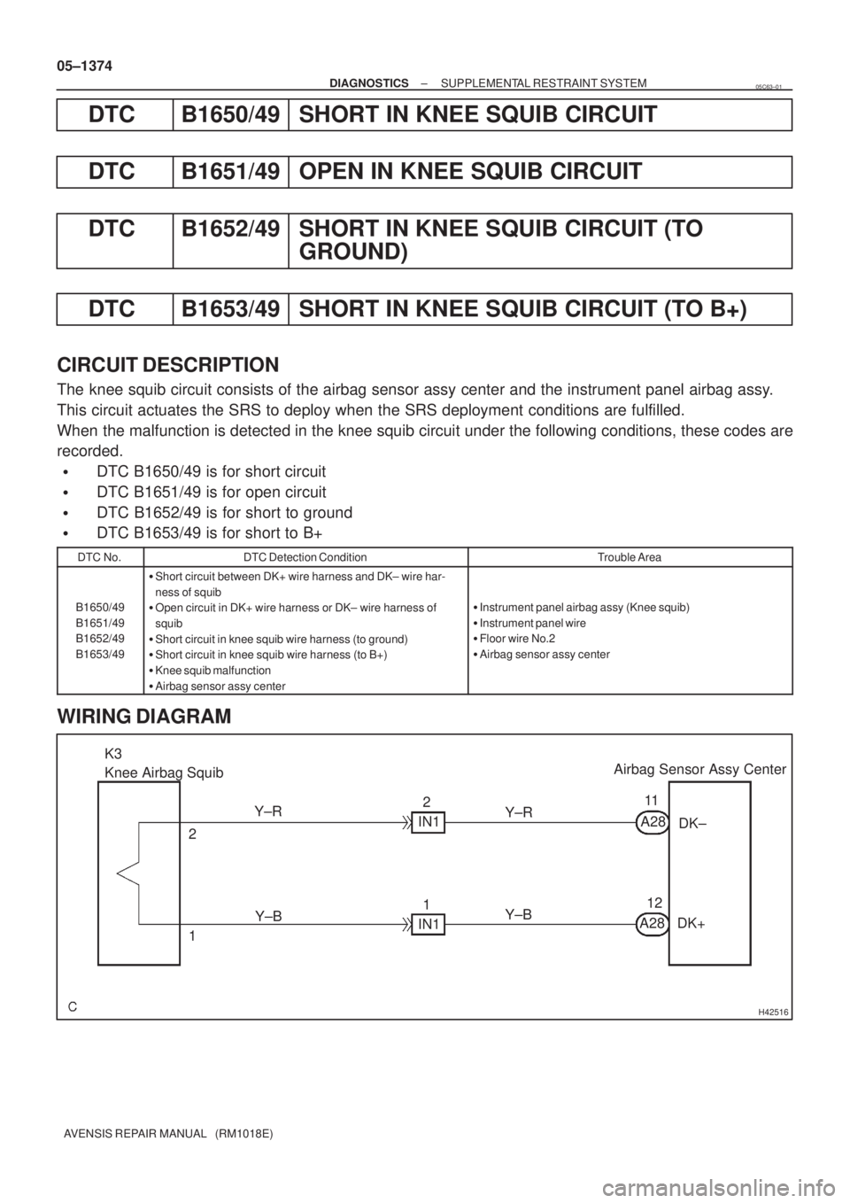
CIRCUIT DESCRIPTION
The knee squib circuit consists of the airbag sensor assy center and the instrument panel airbag assy.
This circuit actuates the SRS to deploy when the SRS deployment conditions are fulfilled.
When the malfunction is detected in the knee squib circuit under the following conditions, these codes are
recorded.
�DTC B1650/49 is for short circuit
�DTC B1651/49 is for open circuit
�DTC B1652/49 is for short to ground
�DTC B1653/49 is for short to B+
DTC No.DTC Detection ConditionTrouble Area
B1650/49
B1651/49
B1652/49
B1653/49
�Short circuit between DK+ wire harness and DK± wire har-
ness of squib
�Open circuit in DK+ wire harness or DK± wire harness of
squib
�Short circuit in knee squib wire harness (to ground)
�Short circuit in knee squib wire harness (to B+)
�Knee squib malfunction
�Airbag sensor assy center
�Instrument panel airbag assy (Knee squib)
�Instrument panel wire
�Floor wire No.2
�Airbag sensor assy center
WIRING DIAGRAM
05C63±01
Page 1454 of 5135

������������H40584
P Squib
(2nd step)Airbag
Sensor
Assy
Center
P2+Instrument Panel Wire
A
B
C
D
±
DIAGNOSTICS SUPPLEMENTAL RESTRAINT SYSTEM
05±1371
AVENSIS REPAIR MANUAL (RM1018E)
DTC B1188/56 SHORT IN P SQUIB (2ND STEP) CIRCUIT
(TO B+)
CIRCUIT DESCRIPTION
The P squib (2nd step) circuit consists of the airbag sensor assy center \
and the instrument panel passenger
airbag assy.
This circuit actuates the SRS to deploy when the SRS deployment conditio\
ns are fulfilled.
DTC B1188/56 is recorded when a short to B+ is detected in the P squib (2nd s\
tep) circuit.
DTC No.DTC Detecting ConditionTrouble Area
B1188/56
�Short circuit in P squib (2nd step) wire harness (to B+)
� P squib (2nd step) malfunction
� Airbag sensor assy center malfunction�Instrument panel passenger airbag assy (P squib, 2nd step)
� Airbag sensor assy center
� Instrument panel wire
WIRING DIAGRAM
See page 05±1362.
INSPECTION PROCEDURE
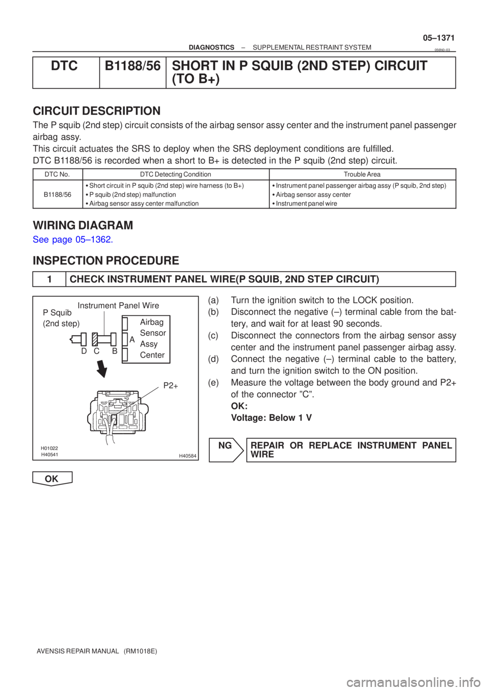
1 CHECK INSTRUMENT PANEL WIRE(P SQUIB, 2ND STEP CIRCUIT)
(a) Turn the ignition switch to the LOCK position.
(b) Disconnect the negative (±) terminal cable from the bat-
tery, and wait for at least 90 seconds.
(c) Disconnect the connectors from the airbag sensor assy center and the instrument panel passenger airbag assy.
(d) Connect the negative (±) terminal cable to the battery,
and turn the ignition switch to the ON position.
(e) Measure the voltage between the body ground and P2+ of the connector ºCº.
OK:
Voltage: Below 1 V
NG REPAIR OR REPLACE INSTRUMENT PANEL WIRE
OK
056N0±03
Page 1460 of 5135
I35619
Steering Pad SW LH
AU1
AU2
EAU12
11
10LG
P
W±RR117
8
6SW1
SW2
GND Radio Receiver Assy
R11
R11 S15
S15
S15 05±1432
± DIAGNOSTICSAUDIO SYSTEM
AVENSIS REPAIR MANUAL (RM1018E)
A AUDIO SYSTEM CANNOT BE OPERATED WITH STEERING PAD
SWITCH
WIRING DIAGRAM
05C55±01
Page 1475 of 5135

± DIAGNOSTICSAUDIO SYSTEM
05±1419
AVENSIS REPAIR MANUAL (RM1018E)
NOISE OCCURS
INSPECTION PROCEDURE
1 CHECK OF SPEAKER INSTALLATION
(a) Check the speaker installation condition.
(1) Check that each speaker is securely installed.
Standard: Malfunction disappears.
HINT:
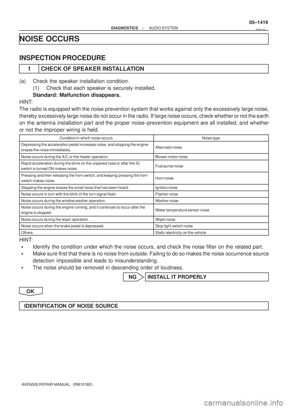
The radio is equipped with the noise prevention system that works against only the excessively large noise,
thereby excessively large noise do not occur in the radio. If large noise occurs, check whether or not the earth
on the antenna installation part and the proper noise±prevention equipment are all installed, and whether
or not the improper wiring is held.
Condition in which noise occursNoise type
Depressing the acceleration pedal increases noise, and stopping the engine
erases the noise immediately.Alternator noise
Noise occurs during the A/C or the heater operation.Blower motor noise
Rapid acceleration during the drive on the unpaved road or after the IG
switch is turned ON makes noise.Fuel pump noise
Pressing and then releasing the horn switch, and keeping pressing the horn
switch makes noise.Horn noise
Stopping the engine erases the small noise that has been heard.Ignition noise
Noise occurs in turn with the blink of the turn signal flash.Flasher noise
Noise occurs during the window washer operation.Washer noise
Noise occurs during the engine running, and it continues to occur after the
engine is stopped.Water temperature sensor noise
Noise occurs during the wiper operation.Wiper noise
Noise occurs when the brake pedal is depressed.Stop light switch noise
Others.Static electricity on the vehicle
HINT:
�Identify the condition under which the noise occurs, and check the noise filter on the related part.
�Make sure first that there is no noise from outside. Failing to do so makes the noise occurrence source
detection impossible and leads to misunderstanding.
�The noise should be removed in descending order of loudness.
NG INSTALL IT PROPERLY
OK
IDENTIFICATION OF NOISE SOURCE
054A1±09
Page 1476 of 5135
I35617
FR+
FR± Radio Receiver Assy
R9 LG (*1)
LG
IL11
L (*1) T15
Front No.2 Speaker Assy RH
F20
Front No.1
Speaker Assy RH1
2
13 P
V2 4 (+) OUT
(±) OUT(±) IN (+) IN
L
IL16
R91
5
P (*2)
IA11
P
4 (+) OUT
(±) OUT(±) IN (+) IN
2 13
1
2
L LGT14
Front No.2 Speaker Assy LH
F19
Front No.1
Speaker Assy LH
V V (*2)
IA16R9
R92
6FL+
FL±
R
R R
IM2
BC19 17 T17
Rear No.2 Speaker Assy RH
(+) OUT
(±) OUT(±) IN (+) IN4
2 13
1
2 B
Y R25
Rear No.1
Speaker Assy RH
WW
W
BC1IM2 7
18R101
RR+
RR±
R103
R10
R102
6 B
B B
Y Y YIC2
IC2 BA1
BA11 7
1710 4
2 (+) OUT
(±) OUT(±) IN (+) IN
13
1
2 R
W T16
Rear No.2 Speaker Assy LH
R24
Rear No.1
Speaker Assy LH
*1: LHD, RHD w/o Multi±display
*2: RHD, LHD w/o Multi±displayRL± RL+
± DIAGNOSTICSAUDIO SYSTEM
05±1415
AVENSIS REPAIR MANUAL (RM1018E)
SOUND QUALITY IS BAD IN ALL MODES (VOLUME IS TOO LOW)
WIRING DIAGRAM
05C50±01
Page 1480 of 5135
I35615
Battery FL MAIN
B±G (*1)B±G (*1)
4B 4A 4D
1 11
12 ALT
B±G (*1) B±G (*1)
Engine Room R/B No.4, Engine Room J/B No.4 1A1 DCC
1 Engine Room R/B No.1, Engine Room J/B No.1 B (*2) B (*2)
33
3 ALT
12W (*2)
ED11 B±L (*2)
B±W
IP1 IE454
(*6) (*3)B±W
6 6
1 2 RAD No.2Fuse Block
Engine Room R/B No.3 L±Y (*3)
L±Y (*4)
L±Y (*5)
INBR (*3)
W±B (*6)R9GND 7 DNDB DH
DH1 134
AM1 RAD No.1 Driver Side J/B
G±R I12 Ignition Switch
AM1 ACC
3 2GGR
J8 J8J20 J20 FF FF J/C
GR
R9 R9
ACC CE CB4
8 Center J/B
L±Y (*3) L±Y (*4) L±Y (*5)L±Y (*5) J24
J/C
EE
4
3+B Radio Receiver Assy
*1: Gasoline
*2: 1CD±FTV
*3: LHD*4: RHD, 1CD±FTV, w/o Multi±display
*5: RHD, Except *4
*6: RHD(*3) (*3)(*6) (*6)
1
2
± DIAGNOSTICSAUDIO SYSTEM
05±1413
AVENSIS REPAIR MANUAL (RM1018E)
POWER SOURCE CIRCUIT (RADIO RECEIVER ASSY)
WIRING DIAGRAM
05C4Z±01