Page 1586 of 5135
I35752
SP1 C11Combination Meter Assy
S135 Skid Control ECU
IE1
L±W
L±W19 16 w/ VSC:
C115
W±B CK CA66
W±B W±B(*1)
W±B(*2) A
J15
J/C
IK IP ILCenter J/B
*1: LHD Models
*2: RHD Models
I35752
SP1 C11Combination Meter Assy
S223 Skid Control ECU
IE1
L±W
L±W19 16 w/o VSC:
C115
W±B CK CA66
W±B W±B(*1)
W±B(*2) A
J15
J/C
IK IP ILCenter J/B
*1: LHD Models
*2: RHD Models 05±1510
± DIAGNOSTICSCOMBINATION METER
AVENSIS REPAIR MANUAL (RM1018E)
MALFUNCTION IN SPEEDOMETER
WIRING DIAGRAM
05C4H±01
Page 1589 of 5135
B66771
KSW
W±B8 U1
Unlock Warning Switch Assy
W±B
IP5
+B GROUND 1
W±R W±B
2
1Instrument Panel J/B Assy
PRG
RDA 16
2PRG
RDA D6
Door Control Receiver
7Integration
Relay
IC2 I14 3 G±Y
L±W 16
7
To
Battery
DA Y
IO*
1
6 8
Center
J/BIC2 G±Y
L±W
CA CD
AJ16
J/C LHD Models
19 I14
A W±B
IL*
2*1: Gasoline Engine
*2: 1CD±FTV
± DIAGNOSTICSWIRELESS DOOR LOCK CONTROL SYSTEM
05±1575
AVENSIS REPAIR MANUAL (RM1018E)
ONLY WIRELESS CONTROL FUNCTION DOES NOT OPERATE
(PREPARE NEW OR NORMAL TRANSMITTER OF THE SAME
TYPE VEHICLE)
CIRCUIT DESCRIPTION
The door control receiver receives a signal from the transmitter and sends this signal to the integration relay.
Then, the integration relay controls door operation by sending a door LOCK/UNLOCK signal and a luggage
door (back door) unlock signal to each door lock motor.
WIRING DIAGRAM
05BNB±01
Page 1600 of 5135

± DIAGNOSTICSWIRELESS DOOR LOCK CONTROL SYSTEM
05±1573
AVENSIS REPAIR MANUAL (RM1018E)
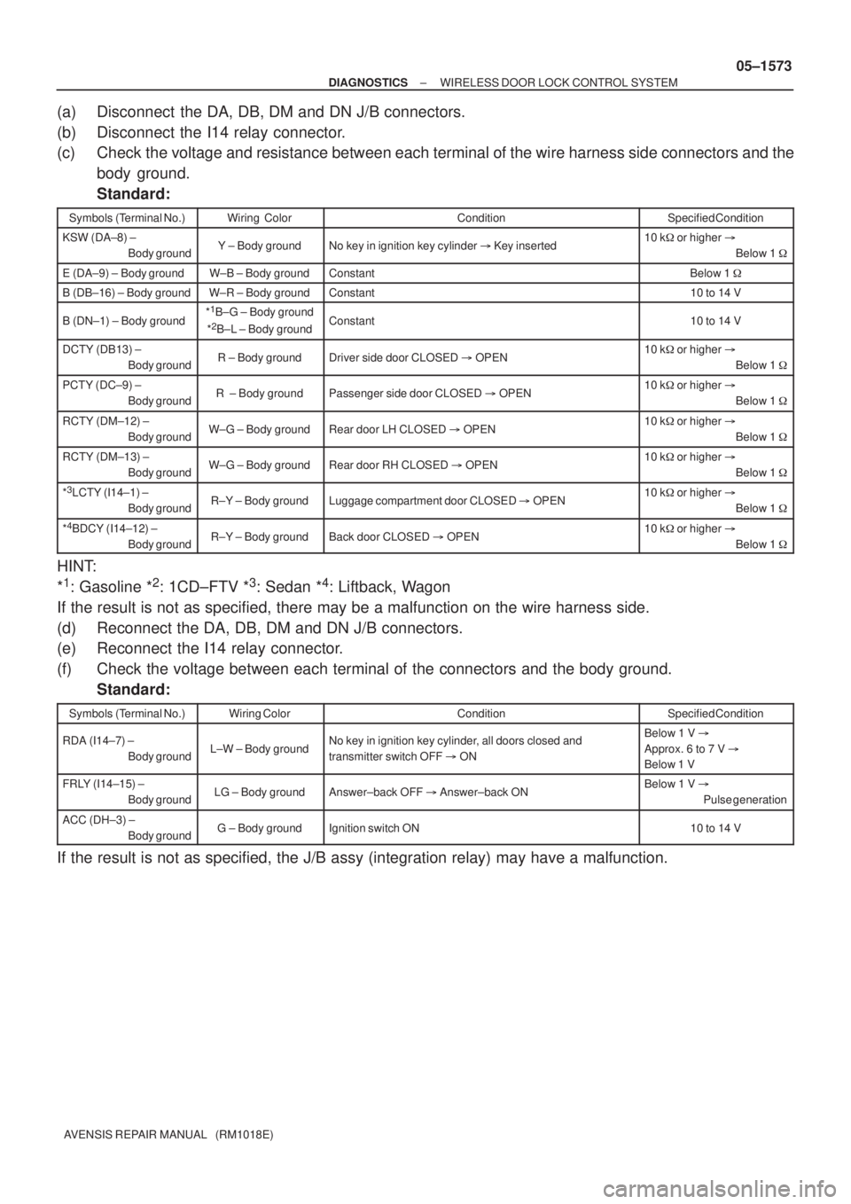
(a) Disconnect the DA, DB, DM and DN J/B connectors.
(b) Disconnect the I14 relay connector.
(c) Check the voltage and resistance between each terminal of the wire harness side connectors and the
body ground.
Standard:
Symbols (Terminal No.)Wiring ColorConditionSpecified Condition
KSW (DA±8) ±
Body groundY ± Body groundNo key in ignition key cylinder � Key inserted10 k� or higher �
Below 1 �
E (DA±9) ± Body groundW±B ± Body groundConstantBelow 1 �
B (DB±16) ± Body groundW±R ± Body groundConstant10 to 14 V
B (DN±1) ± Body ground*1B±G ± Body ground
*2B±L ± Body groundConstant10 to 14 V
DCTY (DB13) ±
Body groundR ± Body groundDriver side door CLOSED � OPEN10 k� or higher �
Below 1 �
PCTY (DC±9) ±
Body groundR ± Body groundPassenger side door CLOSED � OPEN10 k� or higher �
Below 1 �
RCTY (DM±12) ±
Body groundW±G ± Body groundRear door LH CLOSED � OPEN10 k� or higher �
Below 1 �
RCTY (DM±13) ±
Body groundW±G ± Body groundRear door RH CLOSED � OPEN10 k� or higher �
Below 1 �
*3LCTY (I14±1) ±
Body groundR±Y ± Body groundLuggage compartment door CLOSED � OPEN10 k� or higher �
Below 1 �
*4BDCY (I14±12) ±
Body groundR±Y ± Body groundBack door CLOSED � OPEN10 k� or higher �
Below 1 �
HINT:
*
1: Gasoline *2: 1CD±FTV *3: Sedan *4: Liftback, Wagon
If the result is not as specified, there may be a malfunction on the wire harness side.
(d) Reconnect the DA, DB, DM and DN J/B connectors.
(e) Reconnect the I14 relay connector.
(f) Check the voltage between each terminal of the connectors and the body ground.
Standard:
Symbols (Terminal No.)Wiring ColorConditionSpecified Condition
RDA (I14±7) ±
Body groundL±W ± Body groundNo key in ignition key cylinder, all doors closed and
transmitter switch OFF � ONBelow 1 V �
Approx. 6 to 7 V �
Below 1 V
FRLY (I14±15) ±
Body groundLG ± Body groundAnswer±back OFF � Answer±back ONBelow 1 V �
Pulse generation
ACC (DH±3) ±
Body groundG ± Body groundIgnition switch ON10 to 14 V
If the result is not as specified, the J/B assy (integration relay) may have a malfunction.
Page 1606 of 5135
B66822
DLPD
ACTR
ACTS
Front Door w/ Motor Lock Assy RH
Rear Door w/ Motor Lock Assy RH
Front Door w/ Motor Lock Assy LHIntegration Relay
Instrument Panel J/B Assy
I146
D14
D14
D14 D14
9
3
4 10
DJ6
DJ9
D21
D21
D21
5
2 1
D21
D16
D16
D16
6
2 1
D165
Rear Door w/ Motor Lock Assy LH
D19
D19
D19
9
3
4
D1910
RHD Models w/ Double Lock Only
IL2 J20 J21
IC1
IPCJ
CA CH
CF
CE
CI
CK
CB
CA
CD IM1 BC1 IL1
W±B
BC1
BU
IA1B
IA1
17
J20
J20
G
G
GJ/C
J21
G
GB
B3W±B
W±BIL1
IL1
4 8
W
LW
L 5
6
1
1
2
2 3
5 6
10
W±B
W±B
W±B
IJW
L
IA1IA2
W
LW
L
W
L
W
L10 12
BC1
BC1IM2
IM2
4
16
617
11
2
17
4 8
W±B
BA1
10
W±B
BQW
LB
BB
W
L
B
W
L
W
L
IC1
IC3
IC3 BA1
BA1
BA1
4
16
6
4 10 12 9B
B
B BB
9
W
L
W
L15
14 Center J/B
± DIAGNOSTICSPOWER DOOR LOCK CONTROL SYSTEM
05±1561
AVENSIS REPAIR MANUAL (RM1018E)
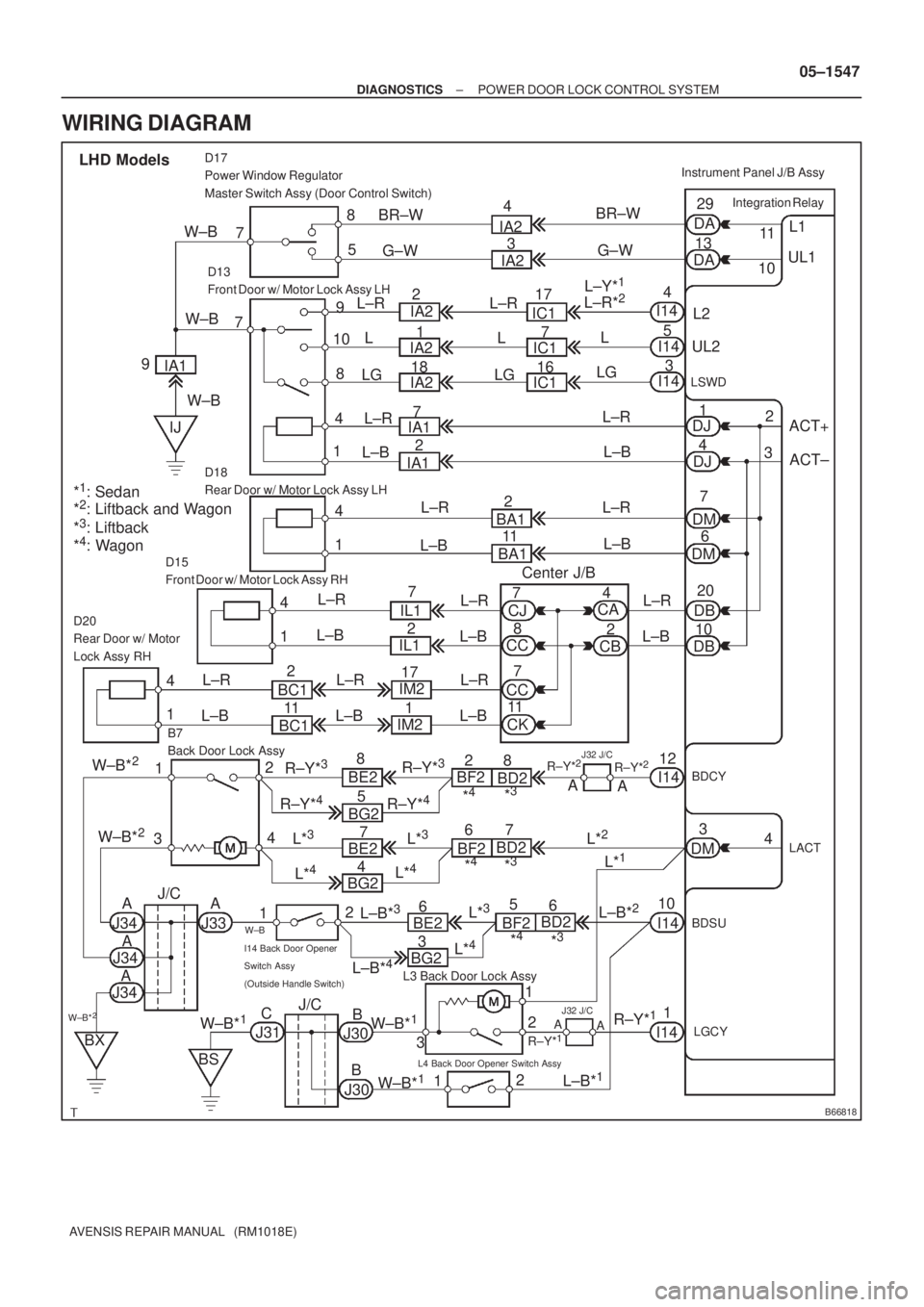
WIRING DIAGRAM
Page 1613 of 5135
B66819
DCTY
Integration Relay
KSW 13
DB D9
Front Door Courtesy Lamp Switch Assy
(Driver Side)
128
DA U1
Unlock Warning Switch AssyInstrument Panel J/B Assy
1 LHD models
R14
IC2J10
J/C
B
Y W±B J16
J/C
A
*
2: 1CD±FTVB
RR
A
IO*
1
IL*2
*1: Gasoline
W±B17
19
± DIAGNOSTICSPOWER DOOR LOCK CONTROL SYSTEM
05±1555
AVENSIS REPAIR MANUAL (RM1018E)
KEY LOCK±IN PREVENTION FUNCTION DOES NOT WORK
PROPERLY (MANUAL OPERATION AND OPERATION
INTERLOCKED WITH KEY ARE ACTIVE)
CIRCUIT DESCRIPTION
The unlock warning switch turns ON when the key is inserted into the ignition key cylinder. The courtesy
lamp switch turns ON when the driver side door is opened. These 2 switches are monitored by the integration
relay. In order to prevent the key from being locked in, the integration relay controls door locking operation
according to the conditions of these switches so that the doors are not locked with the key locked in.
WIRING DIAGRAM
05C8C±01
Page 1619 of 5135

B66818
ACT+ L1
UL1
Integration Relay
DA
DA11
10 29
13
5 8
D17
Power Window Regulator
Master Switch Assy (Door Control Switch)
7
L2 9
10
18
4 7
D13
Front Door w/ Motor Lock Assy LH
UL2
LSWD
ACT±
20
10
D15
Front Door w/ Motor Lock Assy RH
B7
Back Door Lock AssyInstrument Panel J/B Assy
LHD Models
4
5
3
DJ1
DJ4
DM7
DM6
1 4
D18
Rear Door w/ Motor Lock Assy LH
DB
DB 1 4D20
Rear Door w/ Motor
Lock Assy RH
1 4
BDCYI1412
12
4
3
LACT4
DM3
1
2
3 2
12
L3 Back Door Lock Assy
I14 Back Door Opener
Switch Assy
(Outside Handle Switch)
L4 Back Door Opener Switch Assy
LGCY
1
1BDSU
10 W±BBR±W
IA2
IC1
IA1
BA1
CA
CJ
CC
CC
CK IL1
BC1IM2
BE2
BG2R±Y*
3BF2
BD2
J34A
W±B*2J/C
J31 IA1
IJG±W
IA2
IC1
IC1
IA1BR±W
G±W 4
3
17
7
16
7
2
2
11
BA1 L±R
L
L±R
L±B
Center J/B LG
L±R
L±B
L±R
L±B
L±R
L±B L±R
L±B L±R
L±B
BC1IL1
IM2
R±Y*
3
R±Y*4R±Y*4
8
5 2
117
172
1
W±B*2
W±B*2
BE2
5 4
BG27
L*
4
L*3
J34
J34
BX
BS
J30 W±B*
1C
B
B J30W±B*1
W±B*1
A
AA
J33 BE26*
4*3R±Y*
228
A
A
I14
I14
L±B*
1 A
A
J32 J/C
R±Y*1
R±Y*1
L*3BF2BD2
*4*3
7 6
L*2
L*1
BF2BD26
*4*3
CBL±R
L±B
L±R
L±B
8 7
7
112 4
L±R
L±B
L*
4
L±B*3L±B*2L*3
L±R*2L±Y*1
I14
I14
I14 L
LG
2
3
*
1: Sedan
*2: Liftback and Wagon
*3: Liftback
*4: Wagon9W±B
L±R
L±B
R±Y*2
J/C
BG23
L*
4
L±B*4
J32 J/C
L±R
L
LGIA2
IA22
1
18 IA2
W±B
W±B
± DIAGNOSTICSPOWER DOOR LOCK CONTROL SYSTEM
05±1547
AVENSIS REPAIR MANUAL (RM1018E)
WIRING DIAGRAM
Page 1629 of 5135

± DIAGNOSTICSPOWER DOOR LOCK CONTROL SYSTEM
05±1543
AVENSIS REPAIR MANUAL (RM1018E)
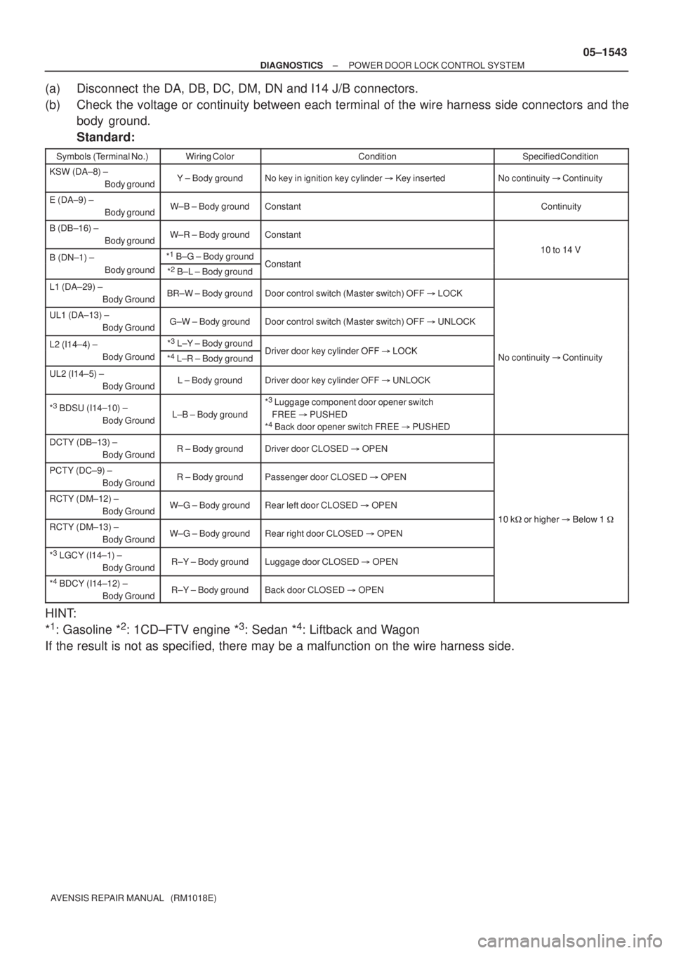
(a) Disconnect the DA, DB, DC, DM, DN and I14 J/B connectors.
(b) Check the voltage or continuity between each terminal of the wire harness side connectors and the
body ground.
Standard:
Symbols (Terminal No.)Wiring ColorConditionSpecified Condition
KSW (DA±8) ±
Body groundY ± Body groundNo key in ignition key cylinder � Key insertedNo continuity � Continuity
E (DA±9) ±
Body groundW±B ± Body groundConstantContinuity
B (DB±16) ±
Body groundW±R ± Body groundConstant
10 to 14 VB (DN±1) ± *1
B±G ± Body groundConstant
10 to 14 VB (DN 1)
Body ground
*2
B±L ± Body groundConstant
L1 (DA±29) ±
Body GroundBR±W ± Body groundDoor control switch (Master switch) OFF � LOCK
UL1 (DA±13) ±
Body GroundG±W ± Body groundDoor control switch (Master switch) OFF � UNLOCK
L2 (I14±4) ± *3
L±Y ± Body groundDriver door key cylinder OFF�LOCKL2 (I14 4)
Body Ground
*4
L±R ± Body groundDriver door key cylinder OFF � LOCKNo continuity � Continuity
UL2 (I14±5) ±
Body GroundL ± Body groundDriver door key cylinder OFF � UNLOCK
yy
*3 BDSU (I14±10) ±
Body GroundL±B ± Body ground
*3 Luggage component door opener switch
FREE � PUSHED
*
4 Back door opener switch FREE � PUSHED
DCTY (DB±13) ±
Body GroundR ± Body groundDriver door CLOSED � OPEN
PCTY (DC±9) ±
Body GroundR ± Body groundPassenger door CLOSED � OPEN
RCTY (DM±12) ±
Body GroundW±G ± Body groundRear left door CLOSED � OPEN
10 k�or higher�Below 1�RCTY (DM±13) ±
Body GroundW±G ± Body groundRear right door CLOSED � OPEN
10 k� or higher � Below 1 �
*3 LGCY (I14±1) ±
Body GroundR±Y ± Body groundLuggage door CLOSED � OPEN
*4 BDCY (I14±12) ±
Body GroundR±Y ± Body groundBack door CLOSED � OPEN
HINT:
*
1: Gasoline *2: 1CD±FTV engine *3: Sedan *4: Liftback and Wagon
If the result is not as specified, there may be a malfunction on the wire harness side.
Page 1630 of 5135

05±1544
± DIAGNOSTICSPOWER DOOR LOCK CONTROL SYSTEM
AVENSIS REPAIR MANUAL (RM1018E)
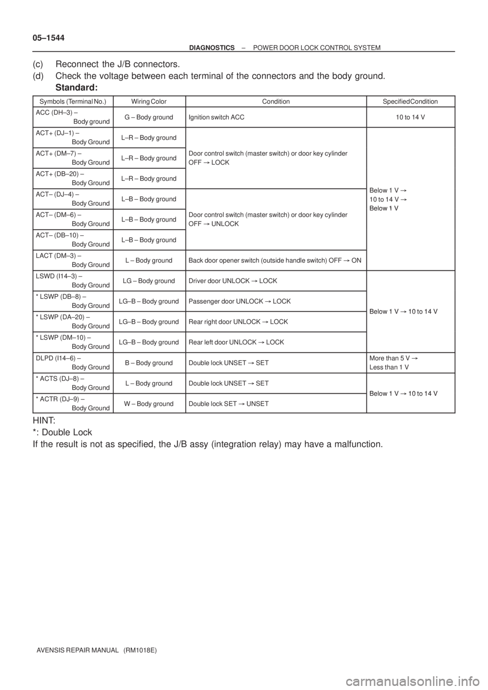
(c) Reconnect the J/B connectors.
(d) Check the voltage between each terminal of the connectors and the body ground.
Standard:
Symbols (Terminal No.)Wiring ColorConditionSpecified Condition
ACC (DH±3) ±
Body groundG ± Body groundIgnition switch ACC10 to 14 V
ACT+ (DJ±1) ±
Body GroundL±R ± Body ground
ACT+ (DM±7) ±
Body GroundL±R ± Body groundDoor control switch (master switch) or door key cylinder
OFF � LOCK
ACT+ (DB±20) ±
Body GroundL±R ± Body ground
Bl 1VACT± (DJ±4) ±
Body GroundL±B ± Body ground
Below 1 V �
10 to 14 V �
Below 1 VACT± (DM±6) ±
Body GroundL±B ± Body groundDoor control switch (master switch) or door key cylinder
OFF � UNLOCKBelow 1 V
ACT± (DB±10) ±
Body GroundL±B ± Body ground
LACT (DM±3) ±
Body GroundL ± Body groundBack door opener switch (outside handle switch) OFF � ON
LSWD (I14±3) ±
Body GroundLG ± Body groundDriver door UNLOCK � LOCK
* LSWP (DB±8) ±
Body GroundLG±B ± Body groundPassenger door UNLOCK � LOCK
Below 1 V�10 to 14 V* LSWP (DA±20) ±
Body GroundLG±B ± Body groundRear right door UNLOCK � LOCK
Below 1 V � 10 to 14 V
* LSWP (DM±10) ±
Body GroundLG±B ± Body groundRear left door UNLOCK � LOCK
DLPD (I14±6) ±
Body GroundB ± Body groundDouble lock UNSET � SETMore than 5 V �
Less than 1 V
* ACTS (DJ±8) ±
Body GroundL ± Body groundDouble lock UNSET � SET
Below 1 V�10 to 14 V* ACTR (DJ±9) ±
Body GroundW ± Body groundDouble lock SET � UNSET
Below 1 V � 10 to 14 V
HINT:
*: Double Lock
If the result is not as specified, the J/B assy (integration relay) may have a malfunction.