Page 5049 of 5135
![TOYOTA AVENSIS 2005 Service Repair Manual G31390
THO
E2 BRE12
28 32
6 E1
Electronically Controlled
Transmission Solenoid
E13 O
1
OVECM
E2OT
– DIAGNOSTICSELECTRONIC CONTROLLED AUTOMATIC
TRANSAXLE [ECT] (U341E) (From February, 2004)05–253
TOYOTA AVENSIS 2005 Service Repair Manual G31390
THO
E2 BRE12
28 32
6 E1
Electronically Controlled
Transmission Solenoid
E13 O
1
OVECM
E2OT
– DIAGNOSTICSELECTRONIC CONTROLLED AUTOMATIC
TRANSAXLE [ECT] (U341E) (From February, 2004)05–253](/manual-img/14/57441/w960_57441-5048.png)
G31390
THO
E2 BRE12
28 32
6 E1
Electronically Controlled
Transmission Solenoid
E13 O
1
OVECM
E2OT
– DIAGNOSTICSELECTRONIC CONTROLLED AUTOMATIC
TRANSAXLE [ECT] (U341E) (From February, 2004)05–253
AVENSIS REPAIR MANUAL SUPPLEMENT
(RM1098E)
WIRING DIAGRAM
INSPECTION PROCEDURE
HINT:
Using the Intelligent Tester II Data List allows switch, sensor, actuator and other item values to be read with-
out removing any parts. Reading the Data List early in troubleshooting is one way to shorten labor time.
NOTICE:
In the table below, the values listed under ”Normal Condition” are reference values. Do not depend
solely on these reference values when deciding whether a part is faulty or not.
(a) Warm up the engine.
(b) Turn the ignition switch off.
(c) Connect the Intelligent Tester II to the DLC3.
(d) Turn the ignition switch to the ON position.
(e) Turn on the tester.
(f) Select the item ”Enter / Power train / Engine and ECT / Data List”.
(g) Follow the instructions on the tester and read the Data List.
ItemMeasurement Item/
Range (display)Normal Condition
A/T Oil Temperature 1
ATF Temp. Sensor Value/
min.: –40�C (–40�F)
max.: 215�C (419�F)�After Stall Test;
Approx. 80�C (176�F)
�Equal to ambient temperature when cold soak
HINT:
When DTC P0712 is output and Intelligent Tester II output is 150�C (302�F) or more, there is a short circuit.
When DTC P0713 is output and Intelligent Tester II output is –40�C (–40�F), there is an open circuit.
Measure the resistance between terminal THO (OT) and body ground.
Temperature DisplayedMalfunction
–40�C (–40�F)Open circuit
150�� (302��� �� ����Short circuit
HINT:
If a circuit related to the ATF temperature sensor becomes open, P0713 is immediately set (in 0.5 second).
When P0713 is set, P0711 cannot be detected.
It is not necessary to inspect the circuit when P0711 is set.
Page 5089 of 5135
05KYD–01
I33809
E13 E12 E11E10E9
– DIAGNOSTICSCRUISE CONTROL SYSTEM (2AZ–FSE)(From
February, 2004)05–315
AVENSIS REPAIR MANUAL SUPPLEMENT
(RM1098E)
TERMINALS OF ECM
Symbols (Terminals No.)Wiring ColorTerminal DescriptionConditionSpecified Condition
TC (E9–20) – E1 (E11–1)W–L – BRDTC input signalIgnition switch ON → Connect ter-
minals TC and CG of DLC310 to 14 V →
Below 2 V
ST1– (E10–12) – E1 (E11–1)G–W – BRCruise cancel input
signalIgnition switch ON, depress brake
pedal → release brake pedalBelow 1 V →
10 to 14 V
STP (E10–19) – E1 (E11–1)G–W – BRStop lamp switch
input signalIgnition switch ON, depress brake
pedal → release brake pedal10 to 14 V →
Below 1 V
CCS (E10–24) – E1 (E11–1)W – BRCruise control main
switch input signal
Ignition switch ON
Cancel switch held ON
SET/COAST switch held ON
RES/ACC switch held ON
MAIN switch held ON10 to 14 V
6.6 to 10.1 V
4.5 to 7.1 V
2.3 to 4 V
Below 1 V
Page 5101 of 5135

600K8–02
H42769
60–6
– SUPPLEMENTAL RESTRAINT SYSTEMAIR BAG SENSOR REAR LH (From February, 2004)
AVENSIS REPAIR MANUAL SUPPLEMENT
(RM1098E)
REPLACEMENT
HINT:
Use the same procedures for the RH side and LH side.
1. PRECAUTION (SEE PUB. NO. RM1018E, PAGE 60–1)
2. DISCONNECT BATTERY NEGATIVE TERMINAL
CAUTION:
After removing the terminal, wait for at least 90 seconds before starting the operation.
3. REMOVE REAR DOOR SCUFF PLATE LH (SEE PUB. NO. RM1018E, PAGE 73–36)
4. REMOVE REAR SEAT CUSHION ASSEMBLY (FIXED TYPE REAR SEAT) (SEE PUB. NO.
RM1018E, PAGE 72–33)
5. REMOVE REAR SIDE SEAT BACK ASSY LH (SEPARATED TYPE REAR SEAT) (SEE PUB. NO.
RM1018E, PAGE 72–27)
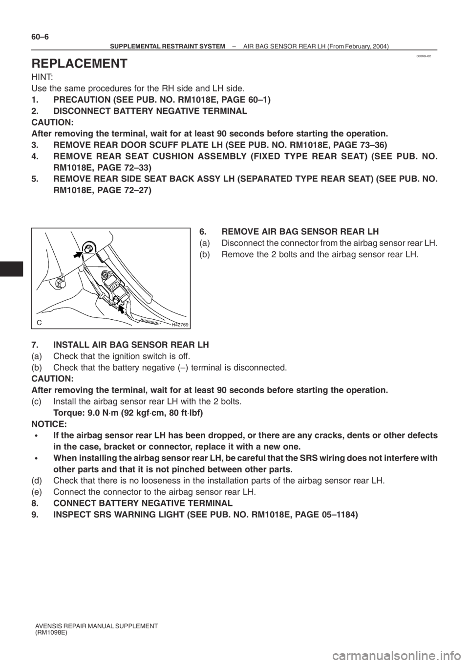
6. REMOVE AIR BAG SENSOR REAR LH
(a) Disconnect the connector from the airbag sensor rear LH.
(b) Remove the 2 bolts and the airbag sensor rear LH.
7. INSTALL AIR BAG SENSOR REAR LH
(a) Check that the ignition switch is off.
(b) Check that the battery negative (–) terminal is disconnected.
CAUTION:
After removing the terminal, wait for at least 90 seconds before starting the operation.
(c) Install the airbag sensor rear LH with the 2 bolts.
Torque: 9.0 N⋅m (92 kgf⋅cm, 80 ft⋅lbf)
NOTICE:
�If the airbag sensor rear LH has been dropped, or there are any cracks, dents or other defects
in the case, bracket or connector, replace it with a new one.
�When installing the airbag sensor rear LH, be careful that the SRS wiring does not interfere with
other parts and that it is not pinched between other parts.
(d) Check that there is no looseness in the installation parts of the airbag sensor rear LH.
(e) Connect the connector to the airbag sensor rear LH.
8. CONNECT BATTERY NEGATIVE TERMINAL
9. INSPECT SRS WARNING LIGHT (SEE PUB. NO. RM1018E, PAGE 05–1184)
Page 5103 of 5135

600A7–04
H42767
60–4– SUPPLEMENTAL RESTRAINT SYSTEMSIDE AIR BAG SENSOR ASSY LH (From February,
2004)
AVENSIS REPAIR MANUAL SUPPLEMENT
(RM1098E)
REPLACEMENT
HINT:
Use the same procedures for the RH side and LH side.
1. PRECAUTION (SEE PUB. NO. RM1018E, PAGE 60–1)
2. DISCONNECT BATTERY NEGATIVE TERMINAL
CAUTION:
After removing the terminal, wait for at least 90 seconds before starting the operation.
3. REMOVE FRONT DOOR SCUFF PLATE LH (SEE PUB. NO. RM1018E, PAGE 76–36)
4. REMOVE REAR DOOR SCUFF PLATE LH (SEE PUB. NO. RM1018E, PAGE 76–36)
5. REMOVE FRONT DOOR WEATHERSTRIP LH (SEE PUB. NO. RM1018E, PAGE 76–36)
6. REMOVE REAR DOOR WEATHERSTRIP LH (SEE PUB. NO. RM1018E, PAGE 76–36)
7. REMOVE CENTER PILLAR GARNISH LOWER LH (SEE PUB. NO. RM1018E, PAGE 76–36)
8. REMOVE FRONT SEAT OUTER BELT ASSY LH (SEE PUB. NO. RM1018E, PAGE 61–7)
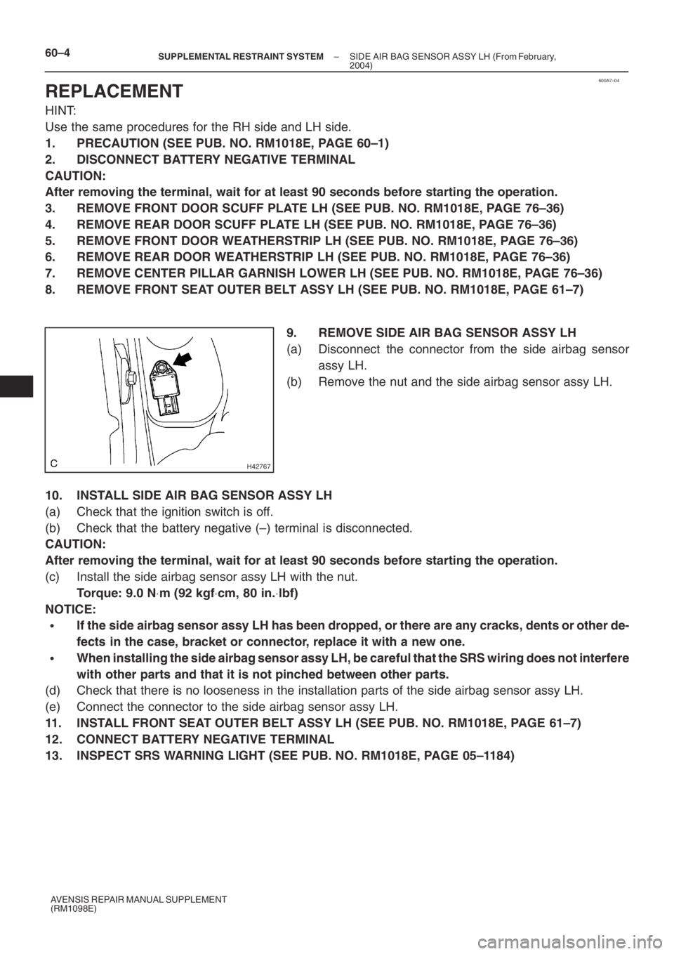
9. REMOVE SIDE AIR BAG SENSOR ASSY LH
(a) Disconnect the connector from the side airbag sensor
assy LH.
(b) Remove the nut and the side airbag sensor assy LH.
10. INSTALL SIDE AIR BAG SENSOR ASSY LH
(a) Check that the ignition switch is off.
(b) Check that the battery negative (–) terminal is disconnected.
CAUTION:
After removing the terminal, wait for at least 90 seconds before starting the operation.
(c) Install the side airbag sensor assy LH with the nut.
Torque: 9.0 N⋅m (92 kgf⋅cm, 80 in.⋅lbf)
NOTICE:
�If the side airbag sensor assy LH has been dropped, or there are any cracks, dents or other de-
fects in the case, bracket or connector, replace it with a new one.
�When installing the side airbag sensor assy LH, be careful that the SRS wiring does not interfere
with other parts and that it is not pinched between other parts.
(d) Check that there is no looseness in the installation parts of the side airbag sensor assy LH.
(e) Connect the connector to the side airbag sensor assy LH.
11. INSTALL FRONT SEAT OUTER BELT ASSY LH (SEE PUB. NO. RM1018E, PAGE 61–7)
12. CONNECT BATTERY NEGATIVE TERMINAL
13. INSPECT SRS WARNING LIGHT (SEE PUB. NO. RM1018E, PAGE 05–1184)
Page 5105 of 5135

600K6–02
H42699
60–2
– SUPPLEMENTAL RESTRAINT SYSTEMAIR BAG SENSOR FRONT LH (From February, 2004)
AVENSIS REPAIR MANUAL SUPPLEMENT
(RM1098E)
REPLACEMENT
HINT:
Use the same procedures for the RH side and LH side.
1. PRECAUTION (SEE PUB. NO. RM1018E, PAGE 60–1)
2. DISCONNECT BATTERY NEGATIVE TERMINAL
CAUTION:
After removing the terminal, wait for at least 90 seconds before starting the operation.
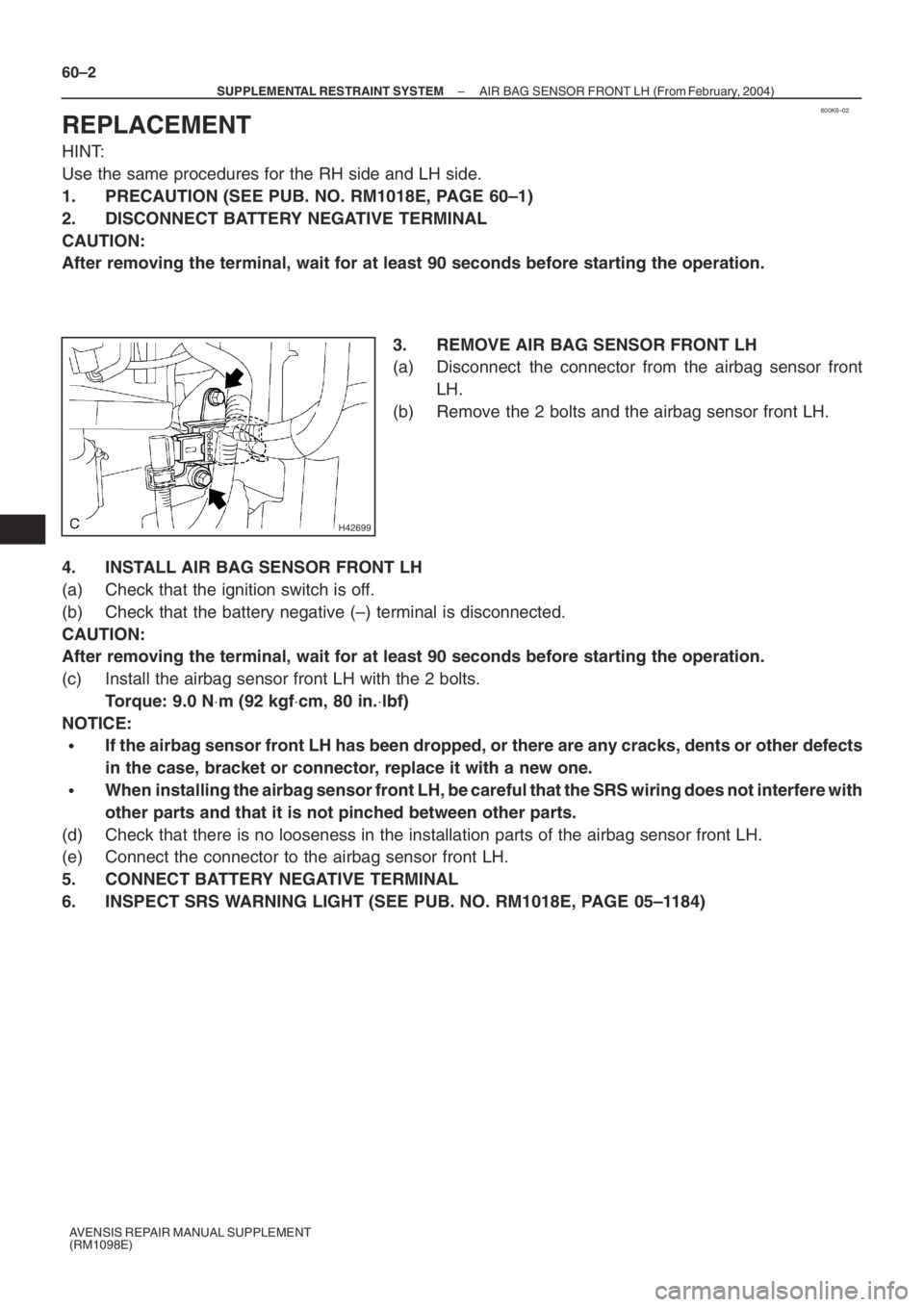
3. REMOVE AIR BAG SENSOR FRONT LH
(a) Disconnect the connector from the airbag sensor front
LH.
(b) Remove the 2 bolts and the airbag sensor front LH.
4. INSTALL AIR BAG SENSOR FRONT LH
(a) Check that the ignition switch is off.
(b) Check that the battery negative (–) terminal is disconnected.
CAUTION:
After removing the terminal, wait for at least 90 seconds before starting the operation.
(c) Install the airbag sensor front LH with the 2 bolts.
Torque: 9.0 N⋅m (92 kgf⋅cm, 80 in.⋅lbf)
NOTICE:
�If the airbag sensor front LH has been dropped, or there are any cracks, dents or other defects
in the case, bracket or connector, replace it with a new one.
�When installing the airbag sensor front LH, be careful that the SRS wiring does not interfere with
other parts and that it is not pinched between other parts.
(d) Check that there is no looseness in the installation parts of the airbag sensor front LH.
(e) Connect the connector to the airbag sensor front LH.
5. CONNECT BATTERY NEGATIVE TERMINAL
6. INSPECT SRS WARNING LIGHT (SEE PUB. NO. RM1018E, PAGE 05–1184)