Page 1665 of 5135
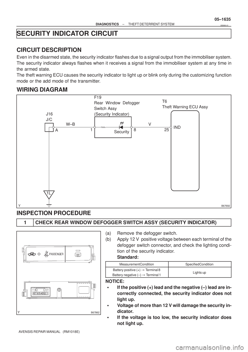
B67692
T6
Theft Warning ECU Assy
IND
25 W±B
1LSecurity A J16
J/C
18V F19
Rear Window Defogger
Switch Assy
(Security Indicator)
B67862
± DIAGNOSTICSTHEFT DETERRENT SYSTEM
05±1635
AVENSIS REPAIR MANUAL (RM1018E)
SECURITY INDICATOR CIRCUIT
CIRCUIT DESCRIPTION
Even in the disarmed state, the security indicator flashes due to a signal output from the immobiliser system.
The security indicator always flashes when it receives a signal from the immobiliser system at any time in
the armed state.
The theft warning ECU causes the security indicator to light up or blink only during the customizing function
mode or the add mode of the transmitter.
WIRING DIAGRAM
INSPECTION PROCEDURE
1 CHECK REAR WINDOW DEFOGGER SWITCH ASSY (SECURITY INDICATOR)
(a) Remove the defogger switch.
(b) Apply 12 V positive voltage between each terminal of the
defogger switch connector, and check the lighting condi-
tion of the security indicator.
Standard:
Measurement ConditionSpecified Condition
Battery positive (+) � Terminal 8
Battery negative (±) � Terminal 1Lights up
NOTICE:
�If the positive (+) lead and the negative (±) lead are in-
correctly connected, the security indicator does not
light up.
�Voltage of more than 12 V will damage the security in-
dicator.
�If the voltage is too low, the security indicator does
not light up.
05BAB±01
Page 1668 of 5135
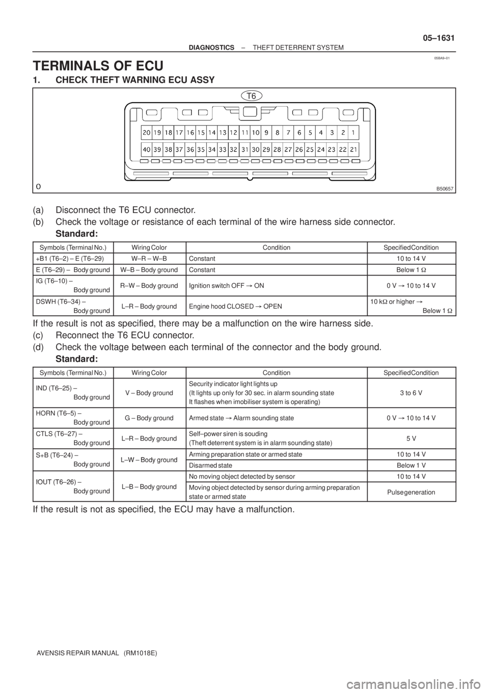
05BA9±01
B50657
T6
± DIAGNOSTICSTHEFT DETERRENT SYSTEM
05±1631
AVENSIS REPAIR MANUAL (RM1018E)
TERMINALS OF ECU
1. CHECK THEFT WARNING ECU ASSY
(a) Disconnect the T6 ECU connector.
(b) Check the voltage or resistance of each terminal of the wire harness side connector.
Standard:
Symbols (Terminal No.)Wiring ColorConditionSpecified Condition
+B1 (T6±2) ± E (T6±29)W±R ± W±BConstant10 to 14 V
E (T6±29) ± Body groundW±B ± Body groundConstantBelow 1 �
IG (T6±10) ±
Body groundR±W ± Body groundIgnition switch OFF � ON0 V � 10 to 14 V
DSWH (T6±34) ±
Body groundL±R ± Body groundEngine hood CLOSED � OPEN10 k� or higher �
Below 1 �
If the result is not as specified, there may be a malfunction on the wire harness side.
(c) Reconnect the T6 ECU connector.
(d) Check the voltage between each terminal of the connector and the body ground.
Standard:
Symbols (Terminal No.)Wiring ColorConditionSpecified Condition
IND (T6±25) ±
Body groundV ± Body ground
Security indicator light lights up
(It lights up only for 30 sec. in alarm sounding state
It flashes when imobiliser system is operating)
3 to 6 V
HORN (T6±5) ±
Body groundG ± Body groundArmed state � Alarm sounding state0 V � 10 to 14 V
CTLS (T6±27) ±
Body groundL±R ± Body groundSelf±power siren is souding
(Theft deterrent system is in alarm sounding state)5 V
S+B (T6±24) ± L W Body groundArming preparation state or armed state10 to 14 VS+B (T6 24)
Body groundL±W ± Body groundDisarmed stateBelow 1 V
IOUT (T6 26)No moving object detected by sensor10 to 14 VIOUT (T6±26) ±
Body groundL±B ± Body groundMoving object detected by sensor during arming preparation
state or armed statePulse generation
If the result is not as specified, the ECU may have a malfunction.
Page 1670 of 5135
± DIAGNOSTICSTHEFT DETERRENT SYSTEM
05±1633
AVENSIS REPAIR MANUAL (RM1018E)
(a) Disconnect the DA, DB, DC, DM and DN J/B connectors.
(b) Disconnect the I14 integration relay connector.
(c) Check the voltage or continuity between each terminal of the wire harness side connectors and the
body ground.
Standard:
Symbols (Terminal No.)Wiring ColorConditionSpecified Condition
KSW (DA±8) ±
Body groundY ± Body groundNo key in ignition key cylinder � Key inserted10 k� or higher �
Below 1 �
E (DA±9) ± Body groundW±B ± Body groundConstantBelow 1 �
B (DB±16) ± Body groundW±R ± Body groundConstant10 to 14 V
B (DN±1) ± Body ground*1B±G ± Body ground
*2B±L ± Body groundConstant10 to 14 V
DCTY (DB±13) ±
Body groundR ± Body groundDriver side door CLOSED � OPEN10 k� or higher �
Below 1 �
PCTY (DC±9) ±
Body groundR ± Body groundPassenger side door CLOSED � OPEN10 k� or higher �
Below 1 �
RCTY (DM±12) ±
Body groundW±G ± Body groundRear door LH CLOSED � OPEN10 k� or higher �
Below 1 �
RCTY (DM±13) ±
Body groundW±G ± Body groundRear door RH CLOSED � OPEN10 k� or higher �
Below 1 �
*3
LGTY (I14±1) ±
Body groundR±Y ± Body groundLuggage compartment door CLOSED � OPEN10 k� or higher �
Below 1 �
*4
BDCY (I14±12) ±
Body groundR±Y ± Body groundBack door CLOSED � OPEN10 k� or higher �
Below 1 �
HINT:
*
1: Gasoline
*
2: 1CD±FTV
*
3: Sedan
*
4: Liftback, Wagon
If the result is not as specified, there may be a malfunction on the wire harness side.
(d) Reconnect the DA, DB, DC, DM and DN J/B connectors.
(e) Reconnect the I14 integration relay connector.
(f) Check the voltage between each terminal of the connector and the body ground.
Standard:
Symbols (Terminal No.)Wiring ColorConditionSpecified Condition
ACC (DH±3) ±
Body groundG ± Body groundIgnition switch ON10 to 14 V
If the result is not as specified, the J/B (integration relay) may have a malfunction.
Page 1675 of 5135
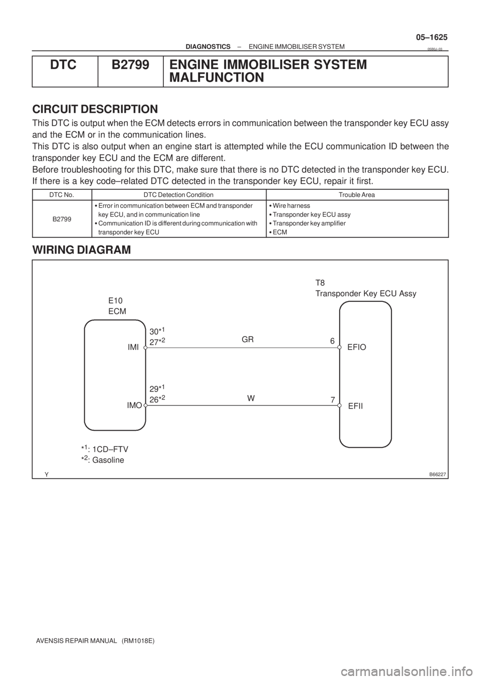
B66227
E10
ECMT8
Transponder Key ECU Assy
IMI
IMO30*
1
27*2
29*1
26*2W GR
6
7EFIO
EFII
*1: 1CD±FTV
*2: Gasoline
± DIAGNOSTICSENGINE IMMOBILISER SYSTEM
05±1625
AVENSIS REPAIR MANUAL (RM1018E)
DTC B2799 ENGINE IMMOBILISER SYSTEM
MALFUNCTION
CIRCUIT DESCRIPTION
This DTC is output when the ECM detects errors in communication between the transponder key ECU assy
and the ECM or in the communication lines.
This DTC is also output when an engine start is attempted while the ECU communication ID between the
transponder key ECU and the ECM are different.
Before troubleshooting for this DTC, make sure that there is no DTC detected in the transponder key ECU.
If there is a key code±related DTC detected in the transponder key ECU, repair it first.
DTC No.DTC Detection ConditionTrouble Area
B2799
�Error in communication between ECM and transponder
key ECU, and in communication line
�Communication ID is different during communication with
transponder key ECU�Wire harness
�Transponder key ECU assy
�Transponder key amplifier
�ECM
WIRING DIAGRAM
05B0J±03
Page 1677 of 5135
B52550
I12
Transponder Key AmplifierT8
Transponder Key ECU Assy
Y±G
CODE
411CODE
05±1624
± DIAGNOSTICSENGINE IMMOBILISER SYSTEM
AVENSIS REPAIR MANUAL (RM1018E)
DTC B2797 COMMUNICATION MALFUNCTION NO.1
CIRCUIT DESCRIPTION
This DTC is output when an error occurs in normal communication.
HINT:
Some noise is found in the communication line.
DTC No.DTC Detection ConditionTrouble Area
B2797Keys are positioned too close to each other or noise oc-
curred in communication line
�Key
�Wire harness
�Transponder key amplifier
�Transponder key ECU assy
WIRING DIAGRAM
INSPECTION PROCEDURE
1 CHECK OPERATION OF TRANSPONDER KEY AMPLIFIER
(a) After replacing the transponder key amplifier, check that the engine starts.
OK NORMAL
(TRANSPONDER KEY AMPLIFIER DEFECTIVE)
NG
REPLACE TRANSPONDER KEY ECU ASSY
05B0I±03
Page 1678 of 5135
B62676
I12
Transponder Key AmplifierT8
Transponder Key ECU Assy
VC5
CODE
TXCT
AGND Y±B
Y±G
L±R
GR±R8
11
12
13 1
4
5
7 TXCT
GND
ANT2 ANT1 VC5
CODE
CoilAmplifier
± DIAGNOSTICSENGINE IMMOBILISER SYSTEM
05±1621
AVENSIS REPAIR MANUAL (RM1018E)
DTC B2796 NO COMMUNICATION IN IMMOBILISER
SYSTEM
DTC B2798 COMMUNICATION MALFUNCTION NO.2
CIRCUIT DESCRIPTION
This code is stored in the memory when a key that does not have a transponder chip is inserted or if commu-
nication between the key and transponder key ECU is impossible.
DTC No.DTC Detection ConditionTrouble Area
B2796No communication
�Key
�Wire harness
�Transponder key amplifier (Transponder key coil)
�Transponder key ECU assy
B2798Communication error�Key
WIRING DIAGRAM
05B0H±03
Page 1684 of 5135
B62676
I12
Transponder Key AmplifierT8
Transponder Key ECU Assy
VC5
CODE
TXCT
AGND Y±B
Y±G
L±R
GR±R8
11
12
13 1
4
5
7 TXCT
GND
ANT2 ANT1 VC5
CODE
CoilAmplifier
05±1616
± DIAGNOSTICSENGINE IMMOBILISER SYSTEM
AVENSIS REPAIR MANUAL (RM1018E)
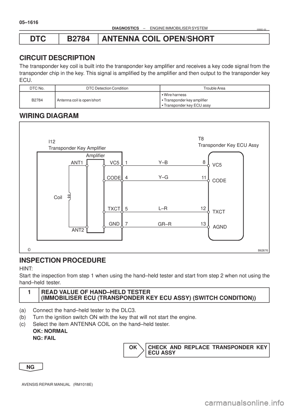
DTC B2784 ANTENNA COIL OPEN/SHORT
CIRCUIT DESCRIPTION
The transponder key coil is built into the transponder key amplifier and receives a key code signal from the
transponder chip in the key. This signal is amplified by the amplifier and then output to the transponder key
ECU.
DTC No.DTC Detection ConditionTrouble Area
B2784Antenna coil is open/short
�Wire harness
�Transponder key amplifier
�Transponder key ECU assy
WIRING DIAGRAM
INSPECTION PROCEDURE
HINT:
Start the inspection from step 1 when using the hand±held tester and start from step 2 when not using the
hand±held tester.
1 READ VALUE OF HAND±HELD TESTER
(IMMOBILISER ECU (TRANSPONDER KEY ECU ASSY) (SWITCH CONDITION))
(a) Connect the hand±held tester to the DLC3.
(b) Turn the ignition switch ON with the key that will not start the engine.
(c) Select the item ANTENNA COIL on the hand±held tester.
OK: NORMAL
NG: FAIL
OK CHECK AND REPLACE TRANSPONDER KEY
ECU ASSY
NG
05B0D±03
Page 1686 of 5135
B66226
T8
Transponder Key ECU Assy
10KSW
12 U1
Un±lock Warning
Switch Assy
IO: Gasoline
IL: 1CD±FTV J16
J/C W±BW±B
Y
J22F
J23 DJ/C
AY
W±B*
1
W±B*2
*1: LHD
*2: RHD IP CA 6CF 13
Center J/BY*
2
DA 6
DA8
Y*
1
Driver Side J/B*1
Passenger Side R/B Assy*2
Y*1
Y*2
W±BA
± DIAGNOSTICSENGINE IMMOBILISER SYSTEM
05±1613
AVENSIS REPAIR MANUAL (RM1018E)
DTC B2780 PUSH SWITCH/KEY UNLOCK WARNING
SWITCH MALFUNCTION
CIRCUIT DESCRIPTION
This DTC will be output if the transponder key ECU does not detect that the unlock warning switch is ON
even when the ignition switch is ON (Under normal conditions, the unlock warning switch is ON when the
ignition switch is ON).
DTC No.DTC Detection ConditionTrouble Area
B2780Unlock warning switch ON is not detected when ignition
switch is ON�Unlock warning switch assy
�Wire harness
�Transponder key ECU assy
WIRING DIAGRAM
05B0C±03