Page 1742 of 5135
I35707
1AZ±FSE
D5
DLC3
TC
CG13
4W±L
W±B
W±B W±LW±L
W±BW±L
TC 20
E12 17 3
DB DC
CB CA36 DBB
B
A J21 J20J8
J8
J16
J/C
IOIP Center J/B Driver Side J/BECM
*2: RHD *1: LHD (*1)(*1)
(*1)(*2)
(*2)
(*2)
(*1) (*2)
(*2) J/B
A
W±B
± DIAGNOSTICSCRUISE CONTROL SYSTEM
05±1729
AVENSIS REPAIR MANUAL (RM1018E)
DIAGNOSIS CIRCUIT
CIRCUIT DESCRIPTION
Making short circuit between terminal TC and CG of DLC3 will output DTC from the DLC3.
WIRING DIAGRAM
05C4V±01
Page 1746 of 5135
I35709
C9
Clutch Start
SW Assy
R±W R±W
R±W R±W
R±W
W±B W±B LG±B
LG±BLG±B
LG±BLG±B
LG±B (*1)
(*2)12 9
515
6
21
568
610 J14
J/C
J19
J/C
DECM
E11
DD
6
IP CPU
CRUISEC11
C11CD
CKCE
CA Center J/B Combination Meter AssyIE2
IR1IE2
IR1 (*1) (*1) (*1) (*1)
CC
(*2)
(*2)(*2)
(*2)
*1: LHD
*2: RHD 1AZ±FSE (M/T) 05±1722
± DIAGNOSTICSCRUISE CONTROL SYSTEM
AVENSIS REPAIR MANUAL (RM1018E)
CRUISE MAIN INDICATOR LIGHT CIRCUIT
CIRCUIT DESCRIPTION
When the cruise control main switch is turned off, the cruise control does not operate.
WIRING DIAGRAM
05C4U±01
Page 1753 of 5135
I35711
C14
Combination SW
CANCEL SET/COASTRES/ACC
CRUISE
CCS
CCSW24
E11
J/C
E J13
J13
J13
J12 ECC 3
BR
BR
BR2 1AZ±FSE
ECU
EE
E
E
D
Cruise Control Main Switch Assy 05±1718
± DIAGNOSTICSCRUISE CONTROL SYSTEM
AVENSIS REPAIR MANUAL (RM1018E)
CRUISE CONTROL SWITCH CIRCUIT
CIRCUIT DESCRIPTION
This circuit carries the SET/COAST, RES/ACC and CANCEL signals (each voltage) to the ECM.
WIRING DIAGRAM
05C4T±01
Page 1759 of 5135
I35714
ECM
19
E11
STP
12
E11 ST1± R±WR±W
G±W
G±W(*1)
(*2)
(*1)
(*2) G±W
R±W
R±W
G±W
G±W(*1)
(*2)
(*1)
(*2) S13
Stop Lamp
Switch Assy
Engine Room R/B G±W
G±W G±W
G±W
B±W B±W
B±W B±W(*1) (*1)
(*2) (*2)
(*1)
(*1)
(*2) (*2)11
2
14
4 6
1
20
3IE3
IR1
IE2
IR1 IE3
IR1
IE1
IR1
4 312
I13
Ignition SW
B±R B±R
IG2 AM24
611
IE4 IP1
(*2) (*1)
B±R
1 1
1AAM2
12
Driver Side J/B Engine Room J/B No.4Driver Side J/B
ALT IGN
1
21
1 4A
4DB±G
1STOP
22
DN DA 1
4B B±G
FL MAIN
Battery2 18
DA DHDA DC10 2Driver Side J/B
J26 J8
J27 J9 AC ECJ/C
B±G (*2)(*2)
(*1)(*1)
*1: LHD
*2: RHD 1AZ±FSE
B±W 05±1712
± DIAGNOSTICSCRUISE CONTROL SYSTEM
AVENSIS REPAIR MANUAL (RM1018E)
WIRING DIAGRAM
Page 1764 of 5135
05±1710
±
DIAGNOSTICS CRUISE CONTROL SYSTEM
AVENSIS REPAIR MANUAL (RM1018E)
DTC P0500/21 VEHICLE SPEED SENSOR ºAº
DTC P0503/23 VEHICLE SPEED SENSOR ºAº INTERMITTENT/ERRATIC/HIGH
CIRCUIT DESCRIPTION
See page 05±453. (1AZ±FSE) See page 05±640. (1CD±FTV)
DTC No.DTC Detection ConditionTrouble Area
P0500/21
The malfunction code is output when the vehicle speed signal
from the vehicle speed sensor is cut for 0.14 sec. or more
while cruise control is in operation.
�Combination meter
� Vehicle speed sensor
P0503/23
Momentary interruption and noise malfunction codes are output
when a rapid change of vehicle speed occurs while cruise
control is in operation.
Vehicle s eed sensor
�Vehicle speed sensor
� ECM
WIRING DIAGRAM
See page 05±453. (1AZ±FSE) See page 05±640. (1CD±FTV)
INSPECTION PROCEDURE
See page 05±453. (1AZ±FSE) See page 05±640. (1CD±FTV)
05C4Q±01
Page 1766 of 5135

05ADL±02
I34746
E8E9
E10E11E12
± DIAGNOSTICSCRUISE CONTROL SYSTEM
05±1707
AVENSIS REPAIR MANUAL (RM1018E)
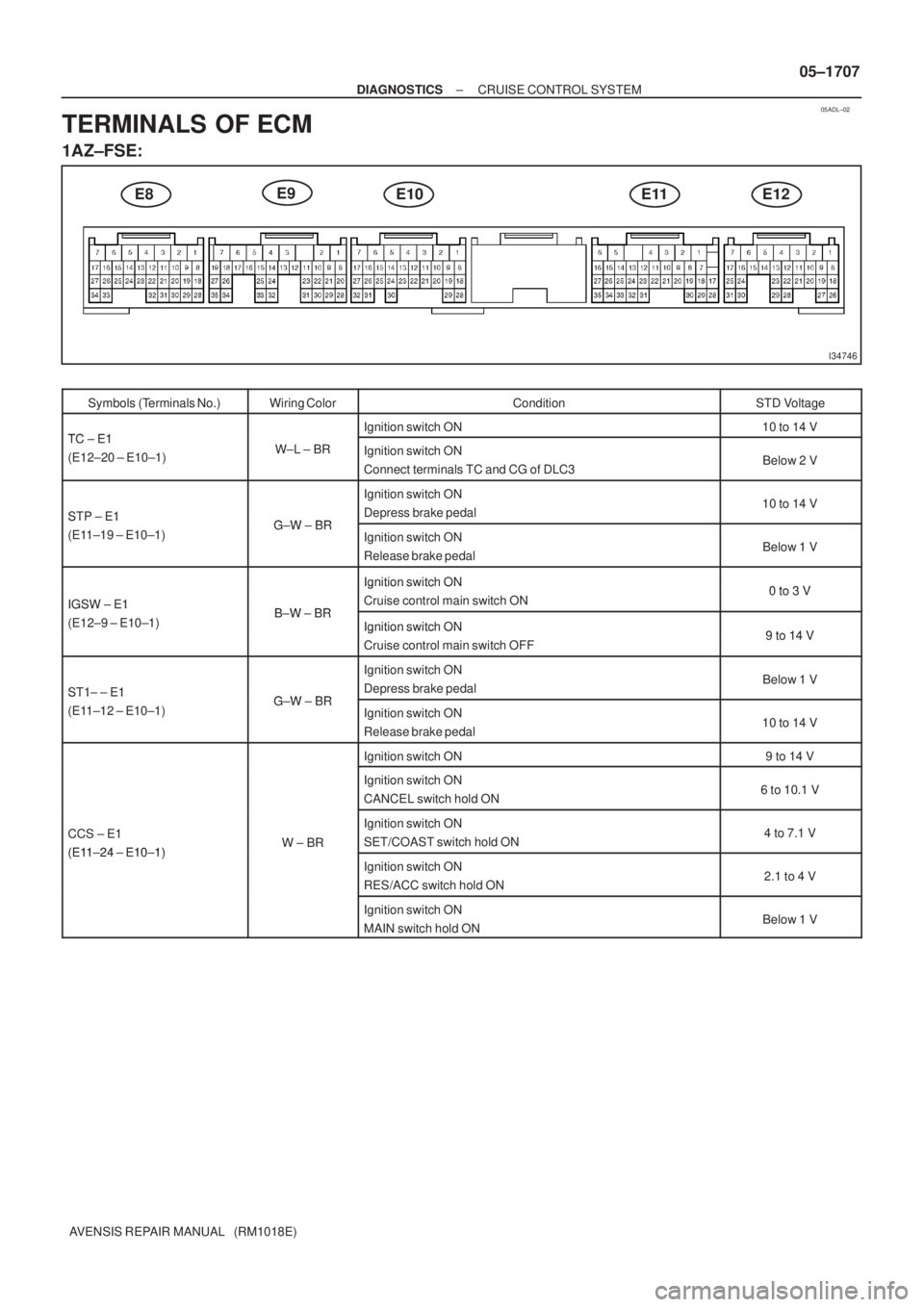
TERMINALS OF ECM
1AZ±FSE:
Symbols (Terminals No.)Wiring ColorConditionSTD Voltage
TC E1Ignition switch ON10 to 14 VTC ± E1
(E12±20 ± E10±1)W±L ± BRIgnition switch ON
Connect terminals TC and CG of DLC3Below 2 V
STP ± E1GW BR
Ignition switch ON
Depress brake pedal10 to 14 VSTP E1
(E11±19 ± E10±1)G±W ± BRIgnition switch ON
Release brake pedalBelow 1 V
Ignition switch ON0to3VIGSW ± E1BW BR
Ignition switch ON
Cruise control main switch ON0 to 3 VIGSW E1
(E12±9 ± E10±1)B±W ± BRIgnition switch ON9to14V()Ignition switch ON
Cruise control main switch OFF9 to 14 V
ST1± ± E1GW BR
Ignition switch ON
Depress brake pedalBelow 1 VST1 E1
(E11±12 ± E10±1)G±W ± BRIgnition switch ON
Release brake pedal10 to 14 V
Ignition switch ON9 to 14 V
Ignition switch ON
CANCEL switch hold ON6 to 10.1 V
CCS ± E1
(E11 24 E10 1)W ± BR
Ignition switch ON
SET/COAST switch hold ON4 to 7.1 V
(E11±24 ± E10±1)Ignition switch ON
RES/ACC switch hold ON2.1 to 4 V
Ignition switch ON
MAIN switch hold ONBelow 1 V
Page 1767 of 5135

I34747
E8E9E12E11 05±1708
± DIAGNOSTICSCRUISE CONTROL SYSTEM
AVENSIS REPAIR MANUAL (RM1018E)
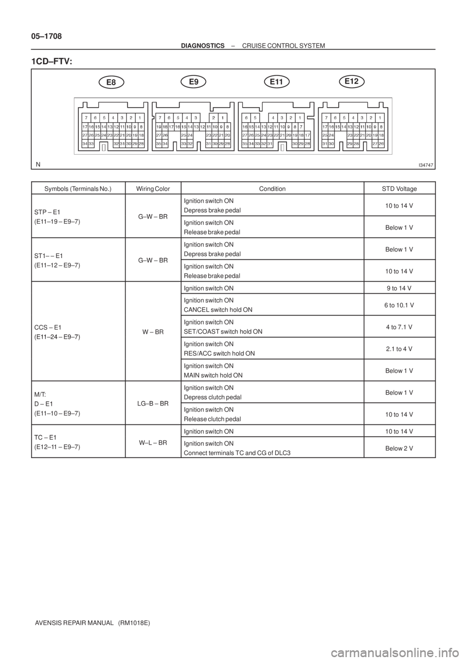
1CD±FTV:
Symbols (Terminals No.)Wiring ColorConditionSTD Voltage
STP ± E1GW BR
Ignition switch ON
Depress brake pedal10 to 14 VSTP E1
(E11±19 ± E9±7)G±W ± BRIgnition switch ON
Release brake pedalBelow 1 V
ST1± ± E1GW BR
Ignition switch ON
Depress brake pedalBelow 1 VST1 E1
(E11±12 ± E9±7)G±W ± BRIgnition switch ON
Release brake pedal10 to 14 V
Ignition switch ON9 to 14 V
Ignition switch ON
CANCEL switch hold ON6 to 10.1 V
CCS ± E1
(E1124 E97)W ± BR
Ignition switch ON
SET/COAST switch hold ON4 to 7.1 V
(E11±24 ± E9±7)Ignition switch ON
RES/ACC switch hold ON2.1 to 4 V
Ignition switch ON
MAIN switch hold ONBelow 1 V
M/T:
DE1LG B BR
Ignition switch ON
Depress clutch pedalBelow 1 V
D ± E1
(E11±10 ± E9±7)LG±B ± BRIgnition switch ON
Release clutch pedal10 to 14 V
TC E1Ignition switch ON10 to 14 VTC ± E1
(E12±11 ± E9±7)W±L ± BRIgnition switch ON
Connect terminals TC and CG of DLC3Below 2 V
Page 1779 of 5135
B67809
Battery113
31 MPX1P
Theft Warning ECU Assy
E10 18
H 22
J/C
+B
W±B*
5
T6 I14
MainW±R*
5
AIC1BEAN
(EFI)
B*
3
POWER
EARTH
3
Instrument Panel J/B Assy
(Integration Relay)
ECMCombination Meter Assy
(Combination Meter ECU)
E9 E923 20
C10
BEAN
(BODY) 14
C10 P±B P±B
BEAN
(SECURITY) 15
C10 P±L*
4
MPX2
MPX
20
C11
C1017 J11 J26 J10
J26F F
F
W±R*
6
W±R
6
6
12DOME
B±W IE4
IP14*
5
5*6
B±W
1
1 2
1A
B±G*
1,
2
B±G*1,
2B*3
3
1
1 4B 4A
W±B*6
A
J16
J/CJ17
J/C
IK
IO*
1,
2,
5
*1: 1AZ±FSE
*2: 1AZ±FE, 1ZZ±FE, 3ZZ±FE
*
3: 1CD±FTV
*
4: w/ Theft Deterrent System
*5: LHD
*
6: RHD *
1*2*3
Engine Room R/BFuse Block Assy
Engine Room J/B No. 4*1,
2Engine Room R/B No. 3*3
DCC
1
AA
W±B*
6
W±BA
J15
J/C
IL*
3,
5
05±1694
± DIAGNOSTICSMULTIPLEX COMMUNICATION SYSTEM
AVENSIS REPAIR MANUAL (RM1018E)
WIRING DIAGRAM