Page 3014 of 5135

600K6±01
H42699
60±64
±
SUPPLEMENTAL RESTRAINT SYSTEM AIR BAG SENSOR FRONT LH
AVENSIS REPAIR MANUAL (RM1018E)
REPLACEMENT
HINT:
Replacement procedure of the RH side is the same as that for with LH side.
1.PRECAUTION (See page 60±1)
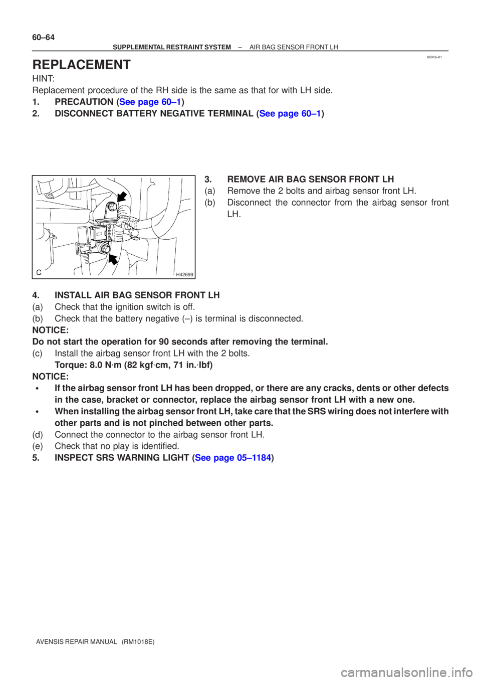
2.DISCONNECT BATTERY NEGATIVE TERMINAL (See page 60±1) 3. REMOVE AIR BAG SENSOR FRONT LH
(a) Remove the 2 bolts and airbag sensor front LH.
(b) Disconnect the connector from the airbag sensor frontLH.
4. INSTALL AIR BAG SENSOR FRONT LH
(a) Check that the ignition switch is off.
(b) Check that the battery negative (±) is terminal is disconnected.
NOTICE:
Do not start the operation for 90 seconds after removing the terminal.
(c) Install the airbag sensor front LH with the 2 bolts. Torque: 8.0 N �m (82 kgf �cm, 71 in. �lbf)
NOTICE:
�If the airbag sensor front LH has been dropped, or there are any cracks,\
dents or other defects
in the case, bracket or connector, replace the airbag sensor front LH with a new one.
�When installing the airbag sensor front LH, take care that the SRS wiring does not interfere\
with
other parts and is not pinched between other parts.
(d) Connect the connector to the airbag sensor front LH.
(e) Check that no play is identified.
5.INSPECT SRS WARNING LIGHT (See page 05±1184)
Page 3016 of 5135

600A1±04
H42701
60±62
±
SUPPLEMENTAL RESTRAINT SYSTEM AIR BAG SENSOR ASSY CENTER
AVENSIS REPAIR MANUAL (RM1018E)
REPLACEMENT
1.PRECAUTION (See page 60±1)
2.DISCONNECT BATTERY NEGATIVE TERMINAL (See page 60±1)
3.REMOVE SHIFT LEVER KNOB SUB±ASSY (M/T TRANSAXLE) (See page 71±11)
4.REMOVE CONSOLE PANEL SUB±ASSY UPPER (See page 71±11)
5.REMOVE CONSOLE PANEL SUB±ASSY LOWER (See page 71±11)
6.REMOVE CONSOLE BOX ASSY RR (See page 71±11)
7.REMOVE AIR DUCT REAR NO.3 (See page 71±11)
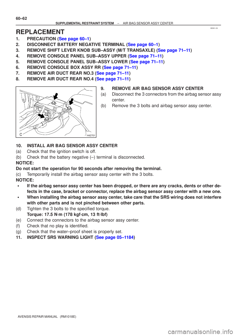
8.REMOVE AIR DUCT REAR NO.4 (See page 71±11) 9. REMOVE AIR BAG SENSOR ASSY CENTER
(a) Disconnect the 3 connectors from the airbag sensor assycenter.
(b) Remove the 3 bolts and airbag sensor assy center.
10. INSTALL AIR BAG SENSOR ASSY CENTER
(a) Check that the ignition switch is off.
(b) Check that the battery negative (±) terminal is disconnected.
NOTICE:
Do not start the operation for 90 seconds after removing the terminal.
(c) Temporarily install the airbag sensor assy center with the 3 bolts.
NOTICE:
�If the airbag sensor assy center has been dropped, or there are any crac\
ks, dents or other de-
fects in the case, bracket or connector, replace the airbag sensor assy center with a new one.
�When installing the airbag sensor assy center, take care that the SRS wiring does not interfere
with other parts and is not pinched between other parts.
(d) Tighten the 3 bolts to the specified torque. Torque: 17.5 N �m (178 kgf �cm, 13 ft �lbf)
(e) Connect the connectors to the airbag sensor assy center.
(f) Check that no play is identified.
(g) Check that the water±proof sheet is properly set.
11.INSPECT SRS WARNING LIGHT (See page 05±1184)
Page 3083 of 5135

600AB±04
H42640
60±70
±
SUPPLEMENTAL RESTRAINT SYSTEM SEAT POSITION AIR BAG SENSOR
AVENSIS REPAIR MANUAL (RM1018E)
REPLACEMENT
HINT:
Replacement procedure of the RH side is the same as that of the LH side.
1.PRECAUTION (See page 60±1)
2.DISCONNECT BATTERY NEGATIVE TERMINAL (See page 60±1)
3.REMOVE SEAT TRACK COVER LH (See page 72±16)
4.REMOVE SEAT TRACK BRACKET COVER INNER LH (See page 72±16)
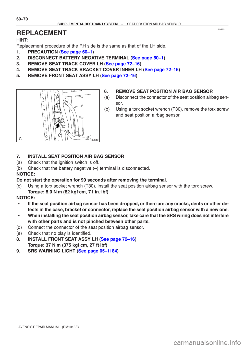
5.REMOVE FRONT SEAT ASSY LH (See page 72±16) 6. REMOVE SEAT POSITION AIR BAG SENSOR
(a) Disconnect the connector of the seat position airbag sen-sor.
(b) Using a torx socket wrench (T30), remove the torx screw and seat position airbag sensor.
7. INSTALL SEAT POSITION AIR BAG SENSOR
(a) Check that the ignition switch is off.
(b) Check that the battery negative (±) terminal is disconnected.
NOTICE:
Do not start the operation for 90 seconds after removing the terminal.
(c) Using a torx socket wrench (T30), install the seat position airbag sen\
sor with the torx screw. Torque: 8.0 N �m (82 kgf �cm, 71 in. �lbf)
NOTICE:
�If the seat position airbag sensor has been dropped, or there are any cracks, dents or other de-
fects in the case, bracket or connector, replace the seat position airbag sensor with a new one.
�When installing the seat position airbag sensor, take care that the SRS wiring does not interfere
with other parts and is not pinched between other parts.
(d) Connect the connector of the seat position airbag sensor.
(e) Check that no play is identified.
8.INSTALL FRONT SEAT ASSY LH (See page 72±16)
Torque: 37 N �m (375 kgf �cm, 27 ft �lbf)
9.SRS WARNING LIGHT (See page 05±1184)
Page 3153 of 5135
6804U±01
I35269
Engine Room No.2 Relay Block
Engine Room Relay Block
Glow Plug Relay AssyEngine Room No.3 Relay Block
Engine Room No.2 Relay Relay
Engine Room No.3 Relay Block
ENGINE:
3ZZ±FE:
1ZZ±FE:
2AZ±FSE:
1AZ±FSE:
1AZ±FE:
ENGINE:
1CD±FTV: w/o Discharge headlamp:
Headlamp Cleaner Control Relay
w/ Discharge headlamp:
Headlamp Cleaner Control Relay Assy
w/o Discharge headlamp:
Headlamp Cleaner Control Relay
w/ Discharge headlamp:
Headlamp Cleaner Control Relay Assy
Engine Room Relay Block
± WIRINGPOWER SOURCE
68±1
AVENSIS REPAIR MANUAL (RM1018E)
POWER SOURCE
LOCATION
Page 3154 of 5135
I35270
Windshield Wiper Relay
Driver Side Relay Block Assy
Turn Signal Flasher Assy
Rear Fog Lamp Relay
Defogger Relay
Circuit Opening
Relay Assy
Instrument Panel
Junction Block Assy
Fuse Block Assy
LHD:
RHD:
Defogger Relay
Rear Fog Lamp RelayPassenger Side Relay Block Assy
Turn Signal Flasher Assy
Windshield Wiper Relay
Fuse Block Assy
Circuit Opening Relay Assy
Instrument Panel Junction Block Assy
68±2
± WIRINGPOWER SOURCE
AVENSIS REPAIR MANUAL (RM1018E)
Page 3155 of 5135
I35135
Engine Room Relay Block
FUSE RELAY
1. EMPS 50A
2. ±
3. A/F 20A
4. THROTTLE 10A
5. HORN 15A6. HAZARD 10A
7. ALT±S 7.5A
8. IG2 15A
9. EFI 20A
10. DCC 30A11. AM2 30A
12. MAIN 40A
13. ±
14. ±
15. ± A. FAN No.2
B. FAN No.1
C. FAN No.3
D. ±
E. ±
F. EMPS12B
CD E
F
11 1016 15
9 814
19 18 13
7 6
1217
34 5
Engine Room Relay Block ENGINE:
3ZZ±FE:
1ZZ±FE:
2AZ±FSE:
1AZ±FSE:
1AZ±FE:
A
16. RR DEF 30A
17. HTR 40A
18. RDI 30A
19. CDS 30A
ENGINE:
1CD±FTV:
1211
10 9 8 7 612
345 B
A
13
15 14
1619 18 17 20
CD
FUSE RELAY
1. MAIN 40A
2. RR DEF 30A
3. PWR HTR 25A
4. EFI 20A
5. HORN 15A6. F±HTR 25A
7. HAZARD 10A
8. AM2 30A
9. DCC 30A
10. ALT±S 7.5A11. ±
12. ±
13. ±
14. *1
15. *2 A. FAN No.1
B. FAN No.3
C. EDU
D. EFI MAIN16. RDI 40A
17. CDS 30A
18. HTR 40A
19. H/CLN 30A
20. AM1 No.1 50A
*1 VSC 25A (w/ VSC)
ABS 25A (w/o VSC)
*2 VSC 50A (w/ VSC)
ABS 40A (w/o VSC)
± WIRINGPOWER SOURCE
68±3
AVENSIS REPAIR MANUAL (RM1018E)
Page 3156 of 5135
I35139
Engine Room No.2 Relay Block
RELAY
A. INJ
B. A/F
C. IG2
D. EFIFUSE
1. EFI No.1 10A
2. EFI No.2 7.5A
3. *1
4. *2
5. H±LP CLN 30A
6. AM1 No.1 50A
7. *3 ENGINE:
3ZZ±FE:
1ZZ±FE:
2AZ±FSE:
1AZ±FSE:
1AZ±FE:
ENGINE:
ICD±FTV:
RELAY
A. HTR1
B. HTR2
C. HTR3FUSE
1. ALT 140A
2. GLOW 80A
3. HTR1 50A
4. HTR2 50A
5. HTR3 50A ABC1
2
345 BC D
5673
1
2
A
4*1 ALT 120A
ALT 100A2AZ±FSE
1AZ±FSE
1AZ±FE
3ZZ±FE
1ZZ±FE
VSC 25A (w/ VSC)
ABS 25A (w/o VSC) *2
Engine Room No.2 Relay BlockVSC 50A (w/ VSC)
ABS 40A (w/o VSC) *3 68±4
± WIRINGPOWER SOURCE
AVENSIS REPAIR MANUAL (RM1018E)
Page 3157 of 5135
I35750
RELAY
A. ±
B. HTR
C. SEAT HTR
D. IG1
E. TAILFUSE
1. IGN 10A
2. S/ROOF 20A
3. RR FOG 7.5A
4. FR FOG 7.5A
5. AM1 25A
6. PANEL 7.5A
7. RR WIP 20A
8. GAUGE2 7.5A
9. CIG 15A
10.HTR 10A
11. ±
12. RAD No.1 7.5A
A. HORN
B. F±HTR
C. H±LP
D. DIM
E. FAN No.2RELAY
1. H±LP HI LH 10A
2. H±LP HI RH 10A
3. H±LP LH 15A
4. H±LP RH 15AFUSE A
B
13
14
15
9
103
4
5
6
7
8
1
3
4 2CD
E
16
17
18
19
20
21
22 12 111
2
A
BCDE13. PWR SEAT 30A
14. TAIL 10A
15. OBD2 7.5A
16. P/POINT 15A
17. DOOR 25A
18. WIP 25A
19. EGU±IG 7.5A
20. S±HTR 20A
21. GAUGE1 10A
22. STOP 15A Instrument Panel Junction Block Assy
Engine Room Relay No.3 Block
± WIRINGPOWER SOURCE
68±5
AVENSIS REPAIR MANUAL (RM1018E)