Page 2745 of 5135
D28038
D28037
LH RH
D28036
D28035
A
DC
B 40±66
± AUTOMATIC TRANSMISSION / TRANSFLOOR SHIFT ASSY
AVENSIS REPAIR MANUAL (RM1018E)
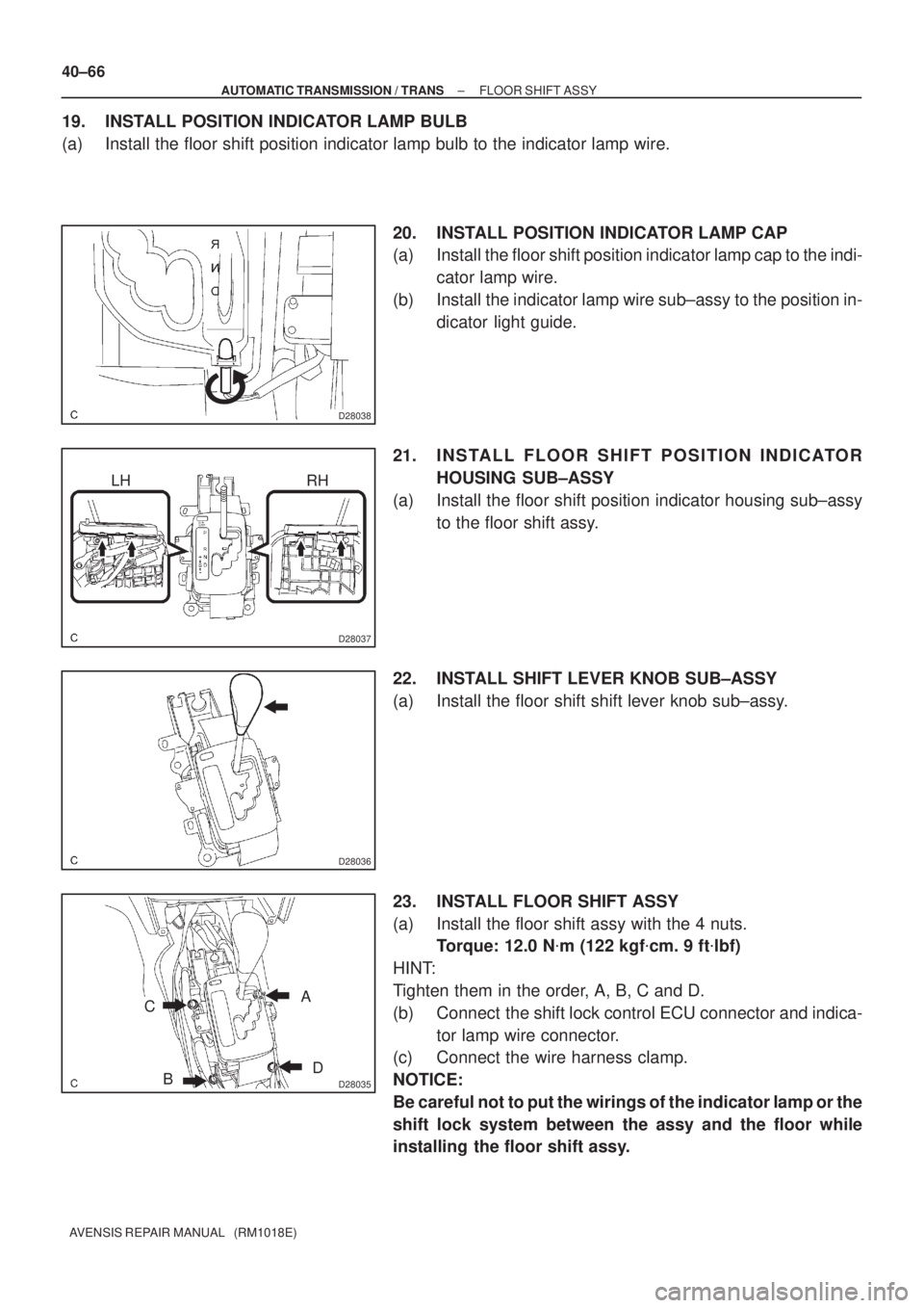
19. INSTALL POSITION INDICATOR LAMP BULB
(a) Install the floor shift position indicator lamp bulb to the indicator lamp wire.
20. INSTALL POSITION INDICATOR LAMP CAP
(a) Install the floor shift position indicator lamp cap to the indi-
cator lamp wire.
(b) Install the indicator lamp wire sub±assy to the position in-
dicator light guide.
21. INSTALL FLOOR SHIFT POSITION INDICATOR
HOUSING SUB±ASSY
(a) Install the floor shift position indicator housing sub±assy
to the floor shift assy.
22. INSTALL SHIFT LEVER KNOB SUB±ASSY
(a) Install the floor shift shift lever knob sub±assy.
23. INSTALL FLOOR SHIFT ASSY
(a) Install the floor shift assy with the 4 nuts.
Torque: 12.0 N�m (122 kgf�cm. 9 ft�lbf)
HINT:
Tighten them in the order, A, B, C and D.
(b) Connect the shift lock control ECU connector and indica-
tor lamp wire connector.
(c) Connect the wire harness clamp.
NOTICE:
Be careful not to put the wirings of the indicator lamp or the
shift lock system between the assy and the floor while
installing the floor shift assy.
Page 2814 of 5135
F44800
Marks
F44801
Torx ScrewScrew Case
±
STEERING COLUMN STEERING COLUMN ASSY
50±19
AVENSIS REPAIR MANUAL (RM1018E)
54.INSTALL INSTRUMENT PANEL AIR BAG ASSY (See page 60±54)
55. INSTALL COLUMN HOLE COVER SILENCER SHEET
56. PLACE FRONT WHEELS FACING STRAIGHT AHEAD
57.INSTALL SPIRAL CABLE SUB±ASSY (See page 60±26)
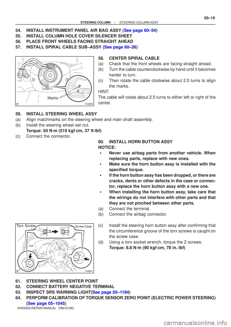
58. CENTER SPIRAL CABLE
(a) Check that the front wheels are facing straight ahead.
(b) Turn the cable counterclockwise by hand until it becomesharder to turn.
(c) Then rotate the cable clockwise about 2.5 turns to align the marks.
HINT:
The cable will rotate about 2.5 turns to either left or right of the
center.
59. INSTALL STEERING WHEEL ASSY
(a) Align matchmarks on the steering wheel and main shaft assembly.
(b) Install the steering wheel set nut. Torque: 50 N´m (510 kgf´cm, 37 ft´lbf)
(c) Connect the connector.
60. INSTALL HORN BUTTON ASSY
NOTICE:
�Never use airbag parts from another vehicle. When
replacing parts, replace with new ones.
�Make sure the horn button assy is installed with the
specified torque.
�If the horn button assy has been dropped, or there are
cracks, dents or other defects in the case or connec-
tor, replace the horn button assy with a new one.
�When installing the horn button assy, take care that
the wirings do not interfere with other parts and that
they are not pinched between other parts.
(a) Connect the terminal.
(b) Connect the airbag connector.
(c) Install the steering horn button assy after confirming that the circumference groove of the torx screws is caught on
the screw case.
(d) Using a torx socket wrench, torque the 2 screws. Torque: 8.8 N´m (90 kgf´cm, 78 in.´lbf)
61. STEERING WHEEL CENTER POINT
62. CONNECT BATTERY NEGATIVE TERMINAL
63.INSPECT SRS WARNING LIGHT(See page 05±1184)
64. PERFORM CALIBRATION OF TORQUE SENSOR ZERO POINT (ELECTRIC POWER STEERING) (See page 05±1045)
Page 2916 of 5135
550ZI±01
I35437
Connector ºBº Wire harness side:
Connector ºAº
I36091
Connector ºBº From back side:
Connector ºAº 55±22
± HEATER & AIR CONDITIONERHOT GAS TYPE POWER HEATER SYSTEM
AVENSIS REPAIR MANUAL (RM1018E)
HOT GAS TYPE POWER HEATER SYSTEM
ON±VEHICLE INSPECTION
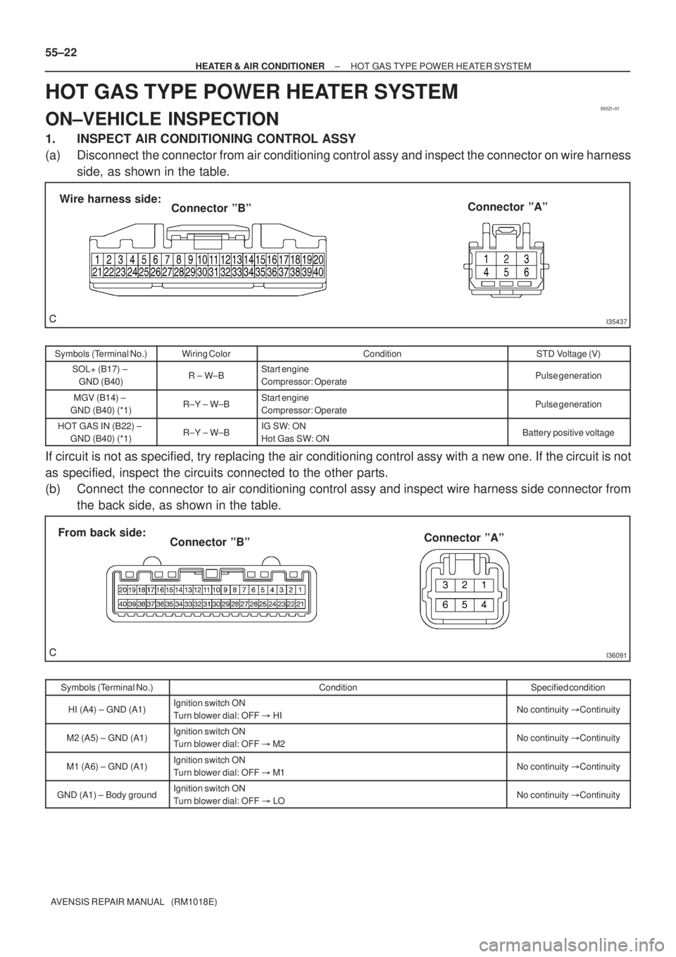
1. INSPECT AIR CONDITIONING CONTROL ASSY
(a) Disconnect the connector from air conditioning control assy and inspect the connector on wire harness
side, as shown in the table.
Symbols (Terminal No.)Wiring ColorConditionSTD Voltage (V)
SOL+ (B17) ±
GND (B40)R ± W±BStart engine
Compressor: OperatePulse generation
MGV (B14) ±
GND (B40) (*1)R±Y ± W±BStart engine
Compressor: OperatePulse generation
HOT GAS IN (B22) ±
GND (B40) (*1)R±Y ± W±BIG SW: ON
Hot Gas SW: ONBattery positive voltage
If circuit is not as specified, try replacing the air conditioning control assy with a new one. If the circuit is not
as specified, inspect the circuits connected to the other parts.
(b) Connect the connector to air conditioning control assy and inspect wire harness side connector from
the back side, as shown in the table.
Symbols (Terminal No.)ConditionSpecified condition
HI (A4) ± GND (A1)Ignition switch ON
Turn blower dial: OFF � HINo continuity �Continuity
M2 (A5) ± GND (A1)Ignition switch ON
Turn blower dial: OFF � M2No continuity �Continuity
M1 (A6) ± GND (A1)Ignition switch ON
Turn blower dial: OFF � M1No continuity �Continuity
GND (A1) ± Body groundIgnition switch ON
Turn blower dial: OFF � LONo continuity �Continuity
Page 2921 of 5135
I35431
Burner Motor
Glow Plug
Surface Sensor
Temp. Control Sensor
Flame Sensor13
Power
Heater
ECU
Connector BTerminal L
of AlternatorBattery
Metering Pump
Fuse (20 A)
Vehicle Side SW 14
9
12
5
6
3
4
1
2R
BR
B±R
G
L±Y
L
Y
L±W5
1
6
2
7
3
8
4W±B
R±G
R±B Connector A
IG
W±R (*1)
Y±R (*2)
R±L (*1)
R±Y (*2)
*1: TMC Made
*2: TMUK Made 55±16
± HEATER & AIR CONDITIONERCOMBUSTION TYPE POWER HEATER SYSTEM
AVENSIS REPAIR MANUAL (RM1018E)
2. DESCRIPTION OF DISPLAY AND BUTTONS
(a) AF: Current Value Malfunction (Blinking at current failure)
Diag: DTC (Example: 064 Flame sensor break)
Memory Clear button: Deletion of faulty memory (Press both buttons together for longer than 2 se-
conds)
> Button: Scroll up of faulty memory (The past 5 codes can be stored.)
< Button: Scroll down of faulty memory (The past 5 codes can be stored.)
3. FAULTY MEMORY
(a) The ECU is able to store up to 5 pieces of faulty memory. If it is full, the new data is written over F5.
4. WIRING DIAGRAM
Page 2955 of 5135
I353162 Claws
I35318
I35319Clamp
I35320
55±66
± HEATER & AIR CONDITIONERBLOWER ASSY
AVENSIS REPAIR MANUAL (RM1018E)
5. REMOVE AIR FILTER CASE
(a) Release the 2 claw fittings and remove the air filter case.
6. REMOVE AIR FILTER
7. REMOVE RECIRCULATION DAMPER SERVO
SUB±ASSY
(a) Remove the 2 screws and the recirculation damper servo
sub±assy.
8. REMOVE AIR CONDITIONING WIRENO1 (MANUAL
AIR CONDITIONING)
(a) Disconnect the connector.
(b) Release the clump and remove the air conditioning wire
No.1.
9. REMOVE COOLER WIRING NO.1 (AUTO AIR CONDITIONING)
HINT:
Disconnection of the cooler wiring No.1 is the same as the air conditioning wire No.1.
10. REMOVE BLOWER RESISTOR (MANUAL AIR
CONDITIONING)
(a) Remove the 2 screws and the blower resistor.
Page 2958 of 5135
550YQ±01
I35277
Blower Assy
Air Duct No.2
Recirculation Damper Servo Sub±assy
Air Filter
Air Filter Case
Blower w/ fan Motor Sub±assy
Manual A/C:
Blower Resistor Air Conditioning Wire No.1
Auto A/C:
Blower Motor Control
9.8 (100, 87 in.�lbf)
Cooler Wiring No.1Manual A/C:
N�m (kgf�cm, ft�lbf): Specified torque
55±64
± HEATER & AIR CONDITIONERBLOWER ASSY
AVENSIS REPAIR MANUAL (RM1018E)
BLOWER ASSY
COMPONENTS
Page 3010 of 5135
600K8±01
H42769
60±68
±
SUPPLEMENTAL RESTRAINT SYSTEM AIR BAG SENSOR REAR LH
AVENSIS REPAIR MANUAL (RM1018E)
REPLACEMENT
HINT:
Replacement procedure of the RH side is the same as that for the LH side.
1.PRECAUTION (See page 60±1)
2.DISCONNECT BATTERY NEGATIVE TERMINAL (See page 60±1)
3.REMOVE REAR DOOR SCUFF PLATE LH (See page 76±36)
4.REMOVE REAR SEAT CUSHION ASSEMBLY (SEDAN MODELS) (See page 76±36)
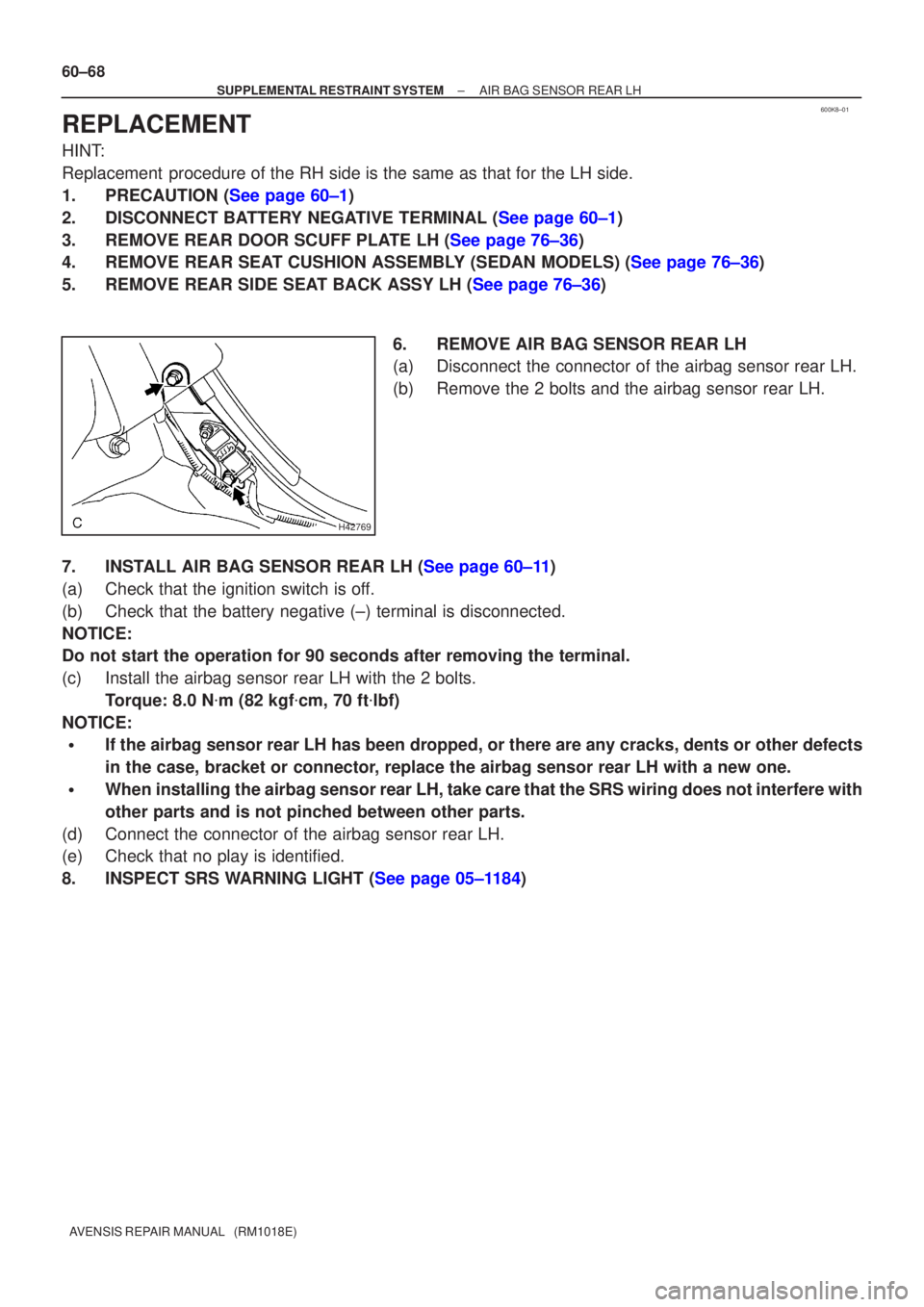
5.REMOVE REAR SIDE SEAT BACK ASSY LH (See page 76±36) 6. REMOVE AIR BAG SENSOR REAR LH
(a) Disconnect the connector of the airbag sensor rear LH.
(b) Remove the 2 bolts and the airbag sensor rear LH.
7.INSTALL AIR BAG SENSOR REAR LH (See page 60±11)
(a) Check that the ignition switch is off.
(b) Check that the battery negative (±) terminal is disconnected.
NOTICE:
Do not start the operation for 90 seconds after removing the terminal.
(c) Install the airbag sensor rear LH with the 2 bolts. Torque: 8.0 N �m (82 kgf �cm, 70 ft �lbf)
NOTICE:
�If the airbag sensor rear LH has been dropped, or there are any cracks, \
dents or other defects
in the case, bracket or connector, replace the airbag sensor rear LH with a new one.
�When installing the airbag sensor rear LH, take care that the SRS wiring does not interfere \
with
other parts and is not pinched between other parts.
(d) Connect the connector of the airbag sensor rear LH.
(e) Check that no play is identified.
8.INSPECT SRS WARNING LIGHT (See page 05±1184)
Page 3012 of 5135
600A7±03
H42767
60±66
±
SUPPLEMENTAL RESTRAINT SYSTEM SIDE AIR BAG SENSOR ASSY LH
AVENSIS REPAIR MANUAL (RM1018E)
REPLACEMENT
HINT:
Replacement procedure of the RH side is the same as that for with LH side.
1.PRECAUTION (See page 60±1)
2.DISCONNECT BATTERY NEGATIVE TERMINAL (See page 60±1)
3.REMOVE FRONT DOOR SCUFF PLATE LH (See page 76±36)
4.REMOVE REAR DOOR SCUFF PLATE LH (See page 76±36)
5.REMOVE FRONT DOOR WEATHERSTRIP LH (See page 76±36)
6.REMOVE REAR DOOR WEATHERSTRIP LH (See page 76±36)
7.REMOVE CENTER PILLAR GARNISH LOWER LH (See page 76±36)
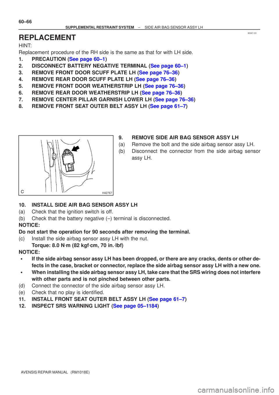
8.REMOVE FRONT SEAT OUTER BELT ASSY LH (See page 61±7) 9. REMOVE SIDE AIR BAG SENSOR ASSY LH
(a) Remove the bolt and the side airbag sensor assy LH.
(b) Disconnect the connector from the side airbag sensorassy LH.
10. INSTALL SIDE AIR BAG SENSOR ASSY LH
(a) Check that the ignition switch is off.
(b) Check that the battery negative (±) terminal is disconnected.
NOTICE:
Do not start the operation for 90 seconds after removing the terminal.
(c) Install the side airbag sensor assy LH with the nut. Torque: 8.0 N �m (82 kgf �cm, 70 in. �lbf)
NOTICE:
�If the side airbag sensor assy LH has been dropped, or there are any cra\
cks, dents or other de-
fects in the case, bracket or connector, replace the side airbag sensor assy LH with a new one.
�When installing the side airbag sensor assy LH, take care that the SRS wiring\
does not interfere
with other parts and is not pinched between other parts.
(d) Connect the connector of the side airbag sensor assy LH.
(e) Check that no play is identified.
11.INSTALL FRONT SEAT OUTER BELT ASSY LH (See page 61±7)
12.INSPECT SRS WARNING LIGHT (See page 05±1184)