Page 1372 of 5135
������������H40584
P Squib
(2nd step)Airbag
Sensor
Assy
Center
P2+
Instrument Panel Wire
A
B
C
D
05±1368
±
DIAGNOSTICS SUPPLEMENTAL RESTRAINT SYSTEM
AVENSIS REPAIR MANUAL (RM1018E)
DTC B1187/55 SHORT IN P SQUIB (2ND STEP) CIRCUIT (TO GROUND)
CIRCUIT DESCRIPTION
The P squib (2nd step) circuit consists of the airbag sensor assy center \
and the instrument panel passenger
airbag assy.
This circuit actuates the SRS to deploy when the SRS deployment conditio\
ns are fulfilled.
DTC B1187/55 is recorded when a short to ground is detected in the P squib (2\
nd step) circuit.
DTC No.DTC Detecting ConditionTrouble Area
B1187/55
�Short circuit in P squib (2nd step) wire harness (to ground)
� P squib (2nd step) malfunction
� Airbag sensor assy center malfunction�Instrument panel passenger airbag assy (P squib, 2nd step)
� Airbag sensor assy center
� Instrument panel wire
WIRING DIAGRAM
See page 05±1362.
INSPECTION PROCEDURE
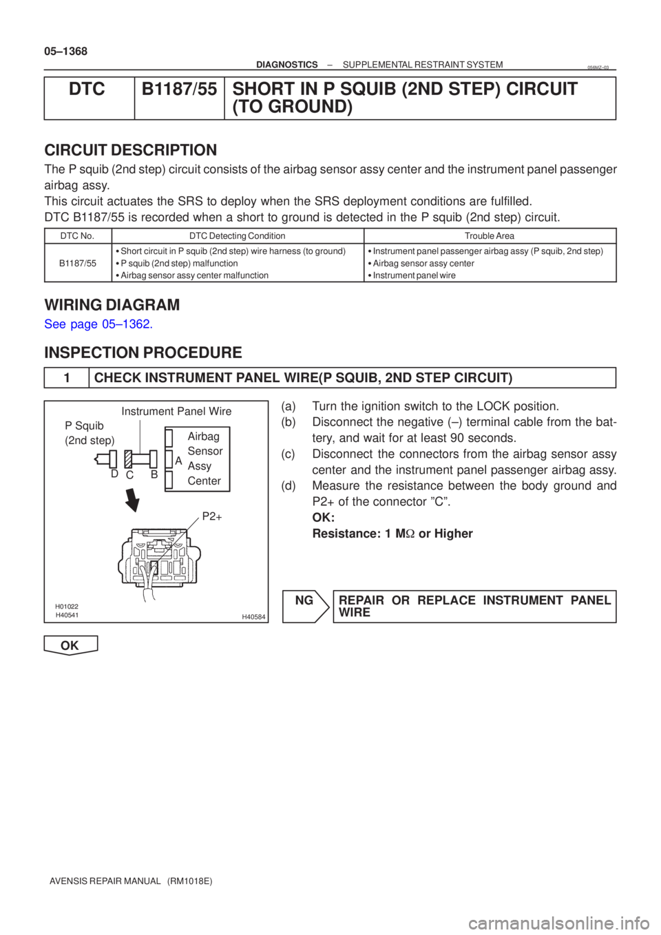
1 CHECK INSTRUMENT PANEL WIRE(P SQUIB, 2ND STEP CIRCUIT)
(a) Turn the ignition switch to the LOCK position.
(b) Disconnect the negative (±) terminal cable from the bat-
tery, and wait for at least 90 seconds.
(c) Disconnect the connectors from the airbag sensor assy center and the instrument panel passenger airbag assy.
(d) Measure the resistance between the body ground and
P2+ of the connector ºCº.
OK:
Resistance: 1 M � or Higher
NG REPAIR OR REPLACE INSTRUMENT PANEL WIRE
OK
056MZ±03
Page 1375 of 5135

�����\b�����H40583
P Squib
(2nd step)Airbag
Sensor
Assy
Center
P2+
P2±Instrument Panel Wire
A
B
C
D
±
DIAGNOSTICS SUPPLEMENTAL RESTRAINT SYSTEM
05±1365
AVENSIS REPAIR MANUAL (RM1018E)
DTC B1186/58 OPEN IN P SQUIB (2ND STEP) CIRCUIT
CIRCUIT DESCRIPTION
The P squib (2nd step) circuit consists of the airbag sensor assy center \
and the instrument panel passenger
airbag assy.
This circuit actuates the SRS to deploy when the SRS deployment conditio\
ns are fulfilled.
DTC B1186/58 is recorded when an open circuit is detected in the P squib (2nd\
step) circuit.
DTC No.DTC Detecting ConditionTrouble Area
B1186/58
�Open circuit in P2+ wire harness or P2± wire harness of P
squib (2nd step)
� P squib (2nd step) malfunction
� Airbag sensor assy center malfunction�Instrument panel passenger airbag assy (P squib, 2nd step)
� Airbag sensor assy center
� Instrument panel wire
WIRING DIAGRAM
See page 05±1362.
INSPECTION PROCEDURE
1 CHECK INSTRUMENT PANEL WIRE(P SQUIB, 2ND STEP CIRCUIT)
(a) Turn the ignition switch to the LOCK position
(b) Disconnect the negative (±) terminal cable from the bat-
tery, and wait for at least 90 seconds.
(c) Disconnect the connectors from the airbag sensor assy center and the instrument panel passenger airbag assy.
(d) Measure the resistance between P2+ and P2± of the con- nector ºCº.
OK:
Resistance: Below 1 �
NG REPAIR OR REPLACE INSTRUMENT PANEL WIRE
OK
056MY±03
Page 1378 of 5135
H01454
A29
P Squib (2nd step)Airbag Sensor Assy Center
Y
Y±B 3
48
P2+ A27
P2± 7
A27 05±1362
± DIAGNOSTICSSUPPLEMENTAL RESTRAINT SYSTEM
AVENSIS REPAIR MANUAL (RM1018E)
DTC B1185/57 SHORT IN P SQUIB (2ND STEP) CIRCUIT
CIRCUIT DESCRIPTION
The P squib (2nd step) circuit consists of the airbag sensor assy center and the instrument panel passenger
airbag assy.
This circuit actuates the SRS to deploy when the SRS deployment conditions are fulfilled.
DTC B1185/57 is recorded when a short circuit is detected in the P squib (2nd step) circuit.
DTC No.DTC Detecting ConditionTrouble Area
B1185/57
�Short circuit between P2+ wire harness and P2± wire harness
of P squib (2nd step)
�P squib (2nd step) malfunction
�Airbag sensor assy center malfunction�Instrument panel passenger airbag assy (P squib, 2nd step)
�Airbag sensor assy center
�Instrument panel wire
WIRING DIAGRAM
056MX±03
Page 1381 of 5135
\b�����������
���
���
H41475
D Squib
(2nd step)
Airbag
Sensor
Assy
Center
Spiral
Cable
Sub±assy
Color: Black
A
B
C
D
E
F
05±1358
±
DIAGNOSTICS SUPPLEMENTAL RESTRAINT SYSTEM
AVENSIS REPAIR MANUAL (RM1018E)
DTC B1183/22 SHORT IN D SQUIB (2ND STEP) CIRCUIT (TO B+)
CIRCUIT DESCRIPTION
The D squib (2nd step) circuit consists of the airbag sensor assy center, the spiral cable sub±assy and the
horn button assy.
This circuit actuates the SRS to deploy when the SRS deployment conditio\
ns are fulfilled.
DTC B1183/22 is recorded when a short to B+ is detected in the D squib (2nd s\
tep) circuit.
DTC No.DTC Detecting ConditionTrouble Area
B1183/22
�Short circuit in D squib (2nd step) wire harness (to B+)
� D squib (2nd step) malfunction
� Spiral cable sub±assy malfunction
� Airbag sensor assy center malfunction�Horn button assy (D squib, 2nd step)
� Spiral cable sub±assy
� Airbag sensor assy center
� Instrument panel wire
WIRING DIAGRAM
See page 05±1346.
CIRCUIT INSPECTION
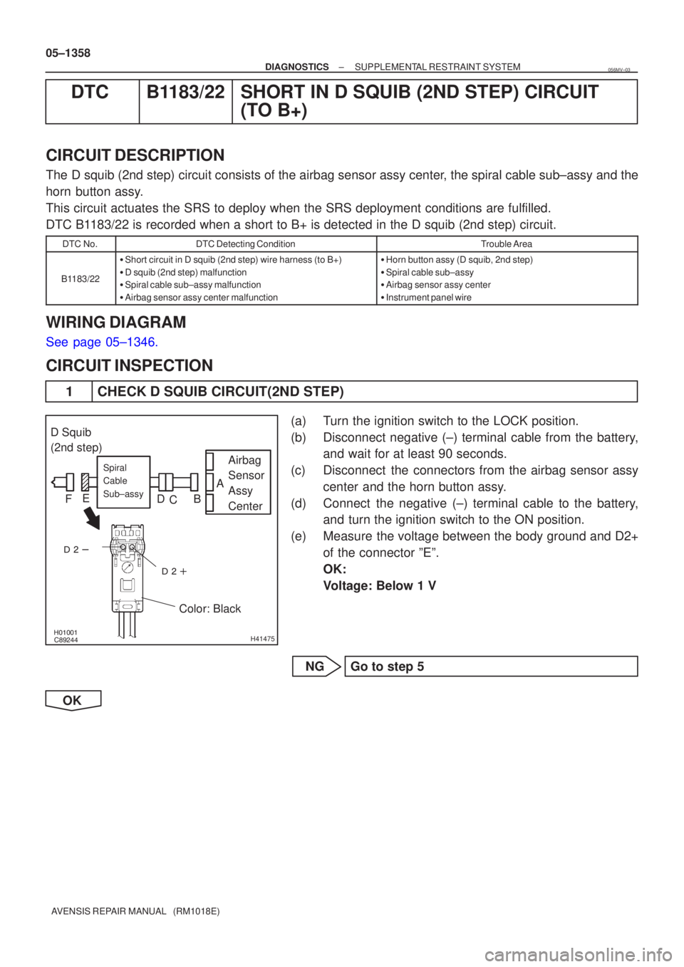
1 CHECK D SQUIB CIRCUIT(2ND STEP)
(a) Turn the ignition switch to the LOCK position.
(b) Disconnect negative (±) terminal cable from the battery,
and wait for at least 90 seconds.
(c) Disconnect the connectors from the airbag sensor assy center and the horn button assy.
(d) Connect the negative (±) terminal cable to the battery, and turn the ignition switch to the ON position.
(e) Measure the voltage between the body ground and D2+ of the connector ºEº.
OK:
Voltage: Below 1 V
NG Go to step 5
OK
056MV±03
Page 1385 of 5135
\b�����������
���
���
H41475
D Squib
(2nd step)
Airbag
Sensor
Assy
Center
Spiral
Cable
Sub±assy
Color: Black
A
B
C
D
E
F
05±1354
±
DIAGNOSTICS SUPPLEMENTAL RESTRAINT SYSTEM
AVENSIS REPAIR MANUAL (RM1018E)
DTC B1182/19 SHORT IN D SQUIB (2ND STEP) CIRCUIT (TO GROUND)
CIRCUIT DESCRIPTION
The D squib (2nd step) circuit consists of the airbag sensor assy center, the spiral cable sub±assy and the
horn button assy.
This circuit actuates the SRS to deploy when the SRS deployment conditio\
ns are fulfilled.
DTC B1182/19 is recorded when a short to ground is detected in the D squib (2\
nd step) circuit.
DTC No.DTC Detecting ConditionTrouble Area
B1182/19
�Short circuit in D squib (2nd step) wire harness (to ground)
� D squib (2nd step) malfunction
� Spiral cable sub±assy malfunction
� Airbag sensor assy center malfunction�Horn button assy (D squib, 2nd step)
� Spiral cable sub±assy
� Airbag sensor assy center
� Instrument panel wire
WIRING DIAGRAM
See page 05±1346.
INSPECTION PROCEDURE
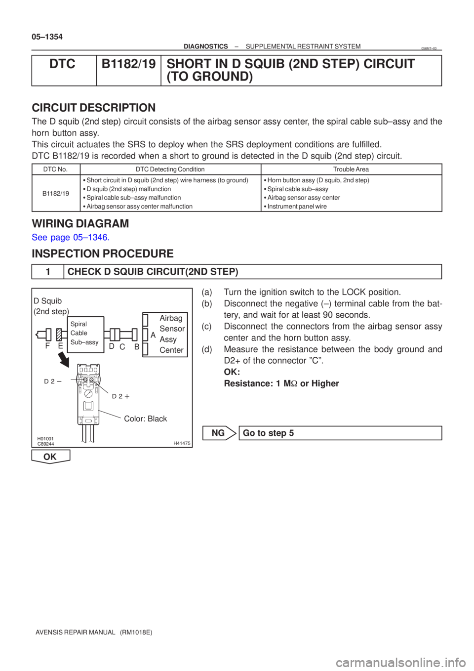
1 CHECK D SQUIB CIRCUIT(2ND STEP)
(a) Turn the ignition switch to the LOCK position.
(b) Disconnect the negative (±) terminal cable from the bat-
tery, and wait for at least 90 seconds.
(c) Disconnect the connectors from the airbag sensor assy center and the horn button assy.
(d) Measure the resistance between the body ground and D2+ of the connector ºCº.
OK:
Resistance: 1 M � or Higher
NG Go to step 5
OK
056MT±03
Page 1389 of 5135
\b�����������
���
���
H41475
D Squib
(2nd step)
Airbag
Sensor
Assy
Center
Spiral
Cable
Sub±assy
Color: Black
A
B
C
D
E
F
05±1350
±
DIAGNOSTICS SUPPLEMENTAL RESTRAINT SYSTEM
AVENSIS REPAIR MANUAL (RM1018E)
DTC B1181/18 OPEN IN D SQUIB (2ND STEP) CIRCUIT
CIRCUIT DESCRIPTION
The D squib (2nd step) circuit consists of the airbag sensor assy center, the spiral cable sub±assy and the
horn button assy.
This circuit actuates the SRS to deploy when the SRS deployment conditio\
ns are fulfilled.
DTC B1181/18 is recorded when an open circuit is detected in the D squib (2nd\
step) circuit.
DTC No.DTC Detecting ConditionTrouble Area
B1181/18
� Open circuit in D2+ wire harness or D2± wire harness of D
squib (2nd step)
� D squib (2nd step) malfunction
� Spiral cable sub±assy malfunction
� Airbag sensor assy center malfunction�Horn button assy (D squib, 2nd step)
� Spiral cable sub±assy
� Airbag sensor assy center
� Instrument panel wire
WIRING DIAGRAM
See page 05±1346.
INSPECTION PROCEDURE
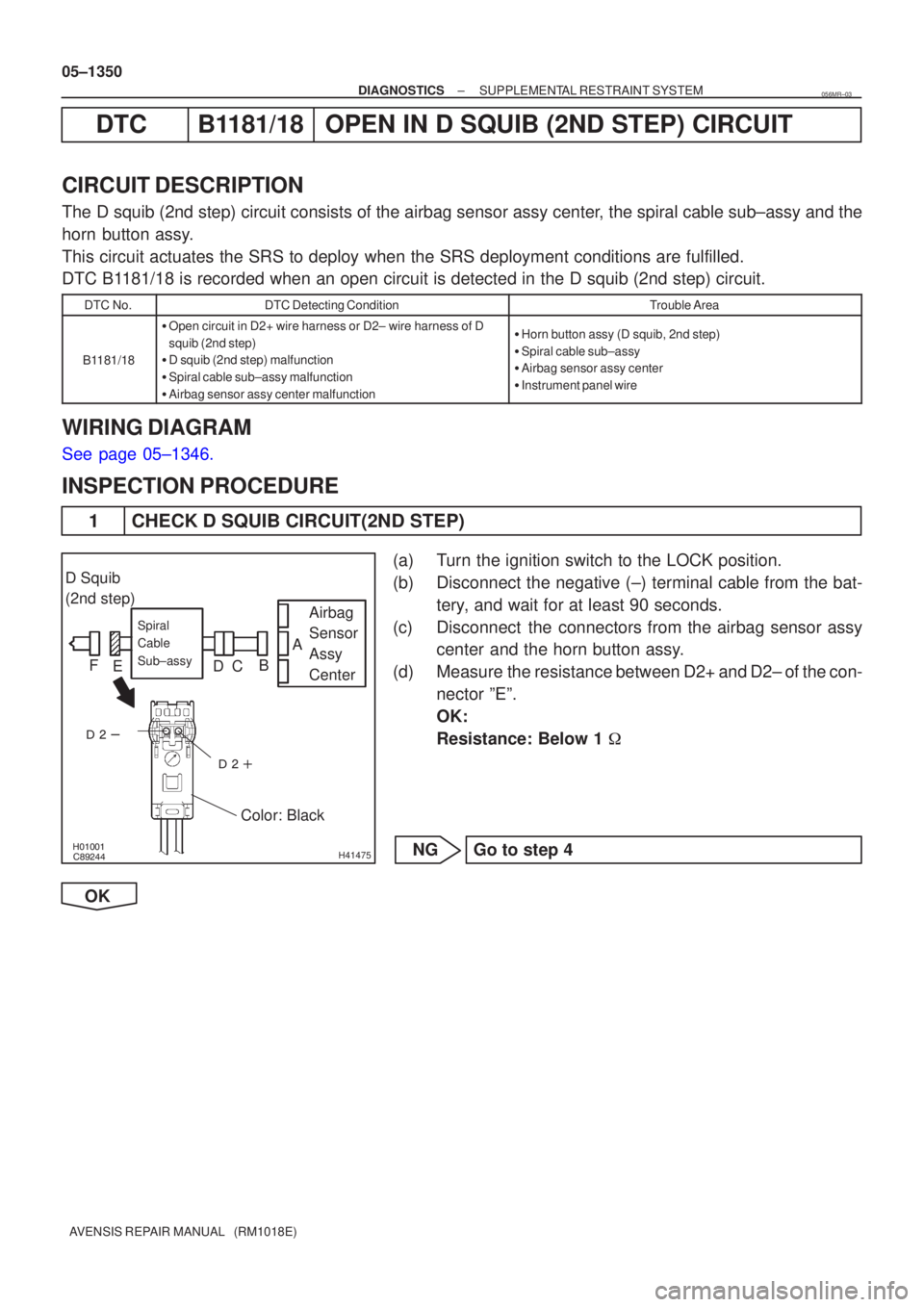
1 CHECK D SQUIB CIRCUIT(2ND STEP)
(a) Turn the ignition switch to the LOCK position.
(b) Disconnect the negative (±) terminal cable from the bat-
tery, and wait for at least 90 seconds.
(c) Disconnect the connectors from the airbag sensor assy center and the horn button assy.
(d) Measure the resistance between D2+ and D2± of the con- nector ºEº.
OK:
Resistance: Below 1 �
NG Go to step 4
OK
056MR±03
Page 1393 of 5135
H01451
Airbag Sensor Assy Center
A30
D Squib (2nd step)
Spiral Cable
Sub±assyY±R Y±G
D2+
D2± 4A27
3A271716 05±1346
± DIAGNOSTICSSUPPLEMENTAL RESTRAINT SYSTEM
AVENSIS REPAIR MANUAL (RM1018E)
DTC B1180/17 SHORT IN D SQUIB (2ND STEP) CIRCUIT
CIRCUIT DESCRIPTION
The D squib (2nd step) circuit consists of the airbag sensor assy center, the spiral cable sub±assy and the
horn button assy.
This circuit actuates the SRS to deploy when the SRS deployment conditions are fulfilled.
DTC B1180/17 is recorded when a short circuit is detected in the D squib (2nd step) circuit.
DTC No.DTC Detecting ConditionTrouble Area
B1180/17
�Short circuit between D2+ wire harness and D2± wire har-
ness of D squib (2nd step)
�D squib (2nd step) malfunction
�Spiral cable sub±assy malfunction
�Airbag sensor assy center malfunction�Horn button assy (D squib, 2nd step)
�Spiral cable sub±assy
�Airbag sensor assy center
�Instrument panel wire
WIRING DIAGRAM
056MQ±03
Page 1397 of 5135
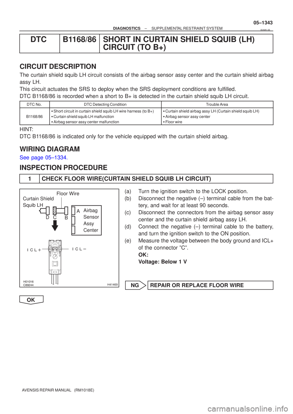
�����
\b�����
����
����
H41469
Curtain Shield
Squib LH
Airbag
Sensor
Assy
Center
Floor Wire
A
B
C
D
±
DIAGNOSTICS SUPPLEMENTAL RESTRAINT SYSTEM
05±1343
AVENSIS REPAIR MANUAL (RM1018E)
DTC B1168/86 SHORT IN CURTAIN SHIELD SQUIB (LH)
CIRCUIT (TO B+)
CIRCUIT DESCRIPTION
The curtain shield squib LH circuit consists of the airbag sensor assy cent\
er and the curtain shield airbag
assy LH.
This circuit actuates the SRS to deploy when the SRS deployment conditio\
ns are fulfilled.
DTC B1168/86 is recorded when a short to B+ is detected in the curtain shield \
squib LH circuit.
DTC No.DTC Detecting ConditionTrouble Area
B1168/86
�Short circuit in curtain shield squib LH wire harness (to B+)
� Curtain shield squib LH malfunction
� Airbag sensor assy center malfunction�Curtain shield airbag assy LH (Curtain shield squib LH)
� Airbag sensor assy center
� Floor wire
HINT:
DTC B1168/86 is indicated only for the vehicle equipped with the curtain shiel\
d airbag.
WIRING DIAGRAM
See page 05±1334.
INSPECTION PROCEDURE
1 CHECK FLOOR WIRE(CURTAIN SHIELD SQUIB LH CIRCUIT)
(a) Turn the ignition switch to the LOCK position.
(b) Disconnect the negative (±) terminal cable from the bat-
tery, and wait for at least 90 seconds.
(c) Disconnect the connectors from the airbag sensor assy center and the curtain shield airbag assy LH.
(d) Connect the negative (±) terminal cable to the battery, and turn the ignition switch to the ON position.
(e) Measure the voltage between the body ground and ICL+ of the connector ºCº.
OK:
Voltage: Below 1 V
NG REPAIR OR REPLACE FLOOR WIRE
OK
054MK±05