Page 2668 of 5135
3300F±07
F44808
Lock NutAdjusting Nut
33±2
±
PARKING BRAKE PARKING BRAKE SYSTEM
AVENSIS REPAIR MANUAL (RM1018E)
ADJUSTMENT
1. REMOVE REAR WHEEL
2.ADJUST PARKING BRAKE SHOE CLEARANCE (See page 33±14)
3. INSTALL REAR WHEEL Torque: 103 N �m (1,050 kgf �cm, 76 ft �lbf)
4. INSPECT PARKING BRAKE LEVER TRAVEL
(a) Pull the parking brake lever all the way up, and count the number of cli\
cks. Parking brake lever travel: 6 ± 9 clicks at 196 N (20 kgf, 44.1 lbf)\
5. ADJUST PARKING BRAKE LEVER TRAVEL
(a) Remove the console box assy RR.(See page71±11)
(b) Loosen the lock nut and turn the adjusting nut until the le- ver travel turns correct.
(c) Tighten the lock nut. Torque: 5.0 N �m (51 kgf �cm, 44 in. �lbf)
(d) Install the console box assy RR.
(See page 71±11)
Page 2669 of 5135
3300E±07
±
PARKING BRAKE PARKING BRAKE SYSTEM
33±1
AVENSIS REPAIR MANUAL (RM1018E)
PARKING BRAKE SYSTEM
PROBLEM SYMPTOMS TABLE
Use the table below to help you find the cause of the problem. The numbers \
indicate the likelihood of the
cause in the descending order. Check each parts in the order shown. Replace these parts as necessary.
SymptomSuspect AreaSee page
Brake drag
1. Parking brake lever travel (Out of adjustment)
2. Parking brake wire (Sticking)
3. Parking brake shoe clearance (Out of adjustment)
4. Parking brake shoe lining (Cracked or distorted)
5. Tension or return spring (Damaged)33±2
33±7
33±10
33±14
33±14
33±14
Page 2670 of 5135

320G5±02
F45426
F45427
F42642
±
BRAKE STEERING SENSOR
32±65
AVENSIS REPAIR MANUAL (RM1018E)
STEERING SENSOR
REPLACEMENT
1.PRECAUTION (See page 60±1)
2. REMOVE PLACE FRONT WHEELS FACING STRAIGHT AHEAD
3.DISCONNECT BATTERY NEGATIVE TERMINAL (See page 60±1)
4.REMOVE HORN BUTTON ASSY (See page 60±17)
5.REMOVE STEERING WHEEL ASSY (See page 50±9)
6.REMOVE STEERING COLUMN COVER LWR (See page 50±9)
7. REMOVE STEERING COLUMN COVER W/INSTRUMENT CLUSTER FINISH PANEL ASSY
(See page 50±9)
8.REMOVE STEERING COLUMN ASSY(See page 50±9)
9.REMOVE STEERING INTERMEDIATE SHAFT ASSY NO.2 (See page 50±9)
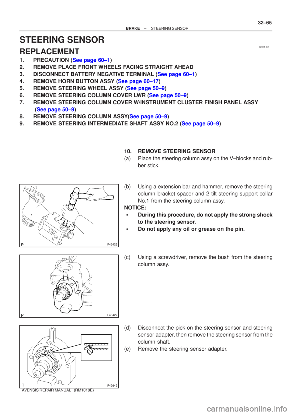
10. REMOVE STEERING SENSOR
(a) Place the steering column assy on the V±blocks and rub-ber stick.
(b) Using a extension bar and hammer, remove the steering column bracket spacer and 2 tilt steering support collar
No.1 from the steering column assy.
NOTICE:
�During this procedure, do not apply the strong shock
to the steering sensor.
�Do not apply any oil or grease on the pin.
(c) Using a screwdriver, remove the bush from the steering column assy.
(d) Disconnect the pick on the steering sensor and steering sensor adapter, then remove the steering sensor from the
column shaft.
(e) Remove the steering sensor adapter.
Page 2671 of 5135

F42641
F42642
F45427
F45426
32±66
±
BRAKE STEERING SENSOR
AVENSIS REPAIR MANUAL (RM1018E)
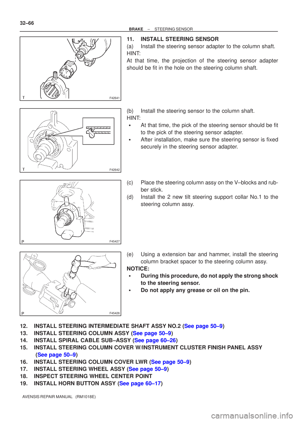
11. INSTALL STEERING SENSOR
(a) Install the steering sensor adapter to the column shaft.
HINT:
At that time, the projection of the steering sensor adapter
should be fit in the hole on the steering column shaft.
(b) Install the steering sensor to the column shaft.
HINT:
�At that time, the pick of the steering sensor should be fit
to the pick of the steering sensor adapter.
�After installation, make sure the steering sensor is fixed
securely in the steering sensor adapter.
(c) Place the steering column assy on the V±blocks and rub- ber stick.
(d) Install the 2 new tilt steering support collar No.1 to the steering column assy.
(e) Using a extension bar and hammer, install the steering column bracket spacer to the steering column assy.
NOTICE:
�During this procedure, do not apply the strong shock
to the steering sensor.
�Do not apply any grease or oil on the pin.
12.INSTALL STEERING INTERMEDIATE SHAFT ASSY NO.2 (See page 50±9)
13.INSTALL STEERING COLUMN ASSY (See page 50±9)
14.INSTALL SPIRAL CABLE SUB±ASSY (See page 60±26)
15. INSTALL STEERING COLUMN COVER W/INSTRUMENT CLUSTER FINISH PANEL ASSY (See page 50±9)
16.INSTALL STEERING COLUMN COVER LWR (See page 50±9)
17.INSTALL STEERING WHEEL ASSY (See page 50±9)
18. INSPECT STEERING WHEEL CENTER POINT
19.INSTALL HORN BUTTON ASSY (See page 60±17)
Page 2672 of 5135
±
BRAKE STEERING SENSOR
32±67
AVENSIS REPAIR MANUAL (RM1018E)
20.CONNECT BATTERY NEGATIVE TERMINAL (See page 60±1)
21.INSPECT SRS WARNING LIGHT (See page 05±1184)
22.INSPECT ABS WARNING LIGHT AND VSC WARNING LIGHT (See page 05±756)
Page 2673 of 5135

320GM±02
G23169
G23170
G23171
G23170
±
BRAKE YAWRATE SENSOR
32±63
AVENSIS REPAIR MANUAL (RM1018E)
YAWRATE SENSOR
REPLACEMENT
NOTICE:
�Don't use the dropped or damaged yawrate sensor.
�Free from the foreing matters between yawrate sensor braket and body.
�Make sure the sensor direction.
1.REMOVE FRONT SEAT ASSEMBLY LH (See page 72±11 or 72±16)
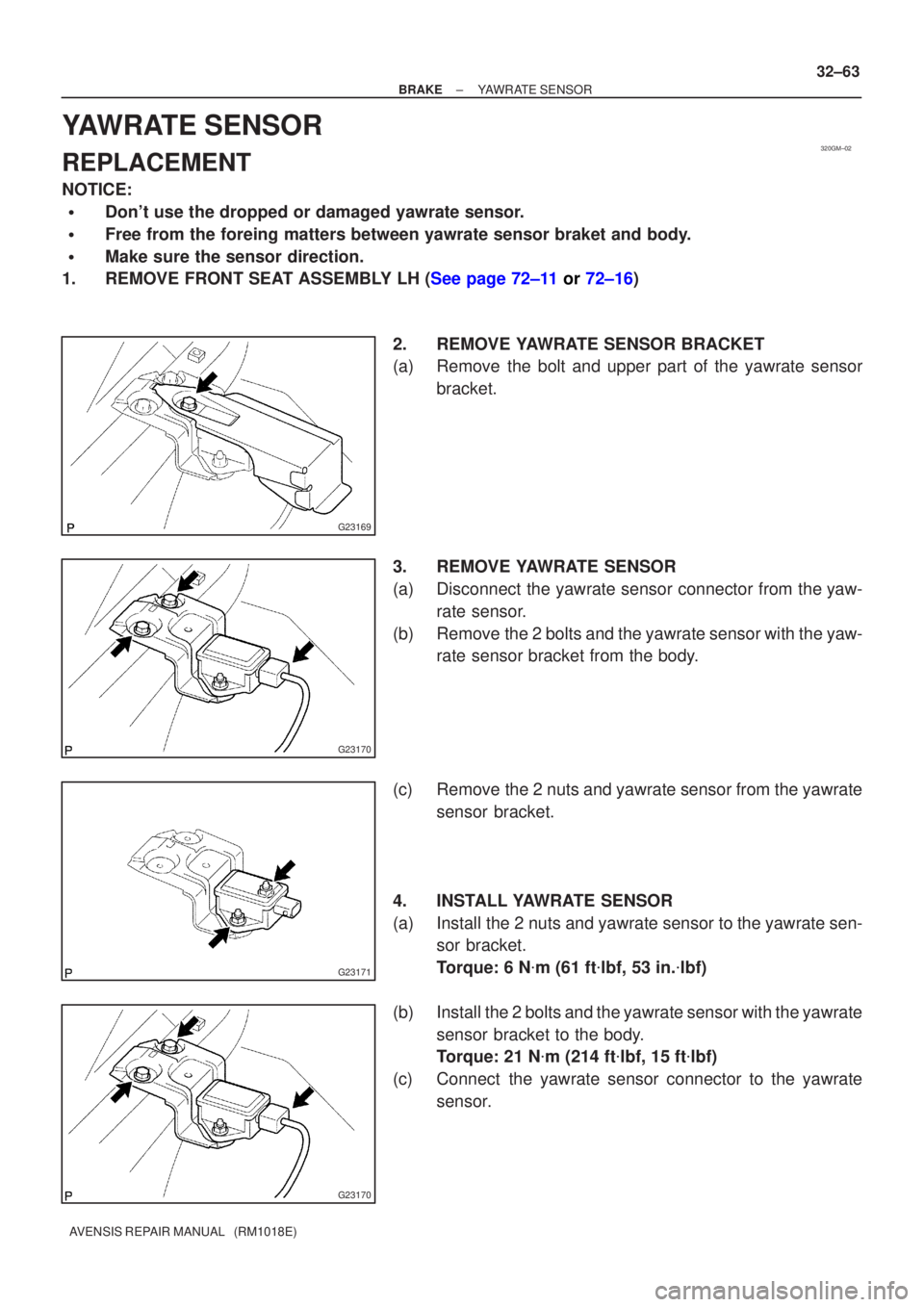
2. REMOVE YAWRATE SENSOR BRACKET
(a) Remove the bolt and upper part of the yawrate sensorbracket.
3. REMOVE YAWRATE SENSOR
(a) Disconnect the yawrate sensor connector from the yaw- rate sensor.
(b) Remove the 2 bolts and the yawrate sensor with the yaw- rate sensor bracket from the body.
(c) Remove the 2 nuts and yawrate sensor from the yawrate sensor bracket.
4. INSTALL YAWRATE SENSOR
(a) Install the 2 nuts and yawrate sensor to the yawrate sen- sor bracket.
Torque: 6 N �m (61 ft �lbf, 53 in. �lbf)
(b) Install the 2 bolts and the yawrate sensor with the yawrate sensor bracket to the body.
Torque: 21 N �m (214 ft �lbf, 15 ft �lbf)
(c) Connect the yawrate sensor connector to the yawrate sensor.
Page 2674 of 5135
G23169
32±64
±
BRAKE YAWRATE SENSOR
AVENSIS REPAIR MANUAL (RM1018E)
5. INSTALL YAWRATE SENSOR BRACKET
(a) Install the bolt and upper part og the yawrate sensor bracket.
Torque: 21 N �m (214 ft �lbf, 15 ft �lbf)
6.INSTALL FRONT SEAT ASSEMBLY LH (See page 72±11 or 72±16)
7.PERFORM YAWRATE SENSOR ZERO POINT CALIBRATION (See page 05±756)
Page 2740 of 5135

400DI±02
D25118
D25119
± AUTOMATIC TRANSMISSION / TRANSFLOOR SHIFT ASSY
40±69
AVENSIS REPAIR MANUAL (RM1018E)
ADJUSTMENT
1. INSPECT SHIFT LEVER POSITION
(a) When the shift lever from P to R position with the ignition switch is ON and the brake pedal is de-
pressed, make sure that the shifting lever moves smoothly and can be moderately operated.
(b) When starting engine, make sure that the vehicle moves forward when shifting from N to D position
and moves rearward when shifting to R position.
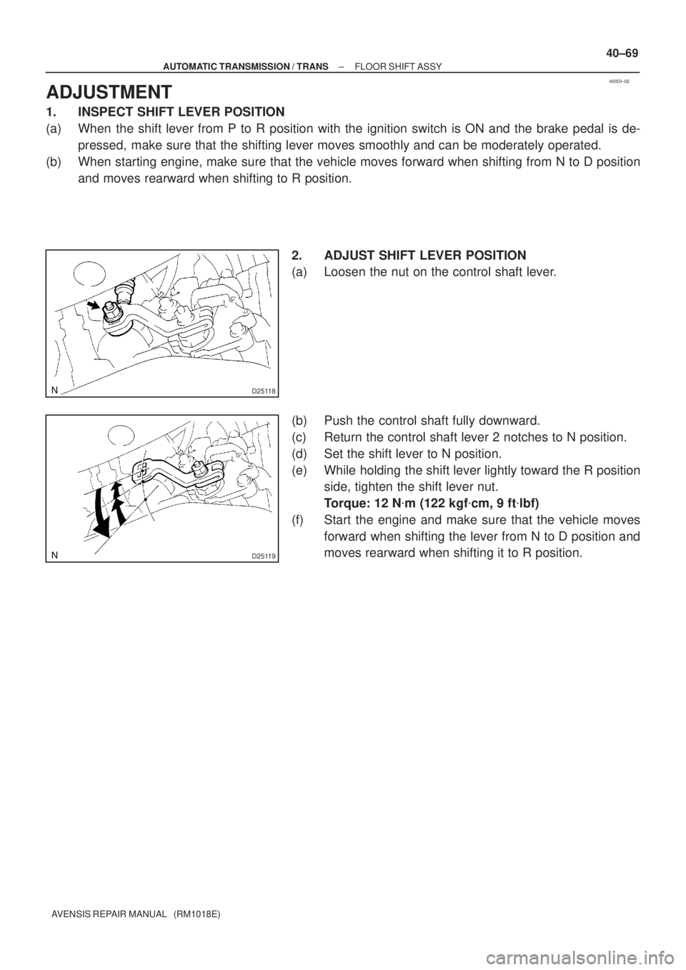
2. ADJUST SHIFT LEVER POSITION
(a) Loosen the nut on the control shaft lever.
(b) Push the control shaft fully downward.
(c) Return the control shaft lever 2 notches to N position.
(d) Set the shift lever to N position.
(e) While holding the shift lever lightly toward the R position
side, tighten the shift lever nut.
Torque: 12 N�m (122 kgf�cm, 9 ft�lbf)
(f) Start the engine and make sure that the vehicle moves
forward when shifting the lever from N to D position and
moves rearward when shifting it to R position.