Page 3588 of 5135
9808S±01
98±6
± COMPONENTS151350
3509/BRAKE NO.3, 1ST & REVERSE BRAKE (ATM)
(0008± )NZE121..ATM U340E
Page 3589 of 5135
9808R±01
± COMPONENTS151350
98±5
3507/BRAKE BAND & MULTIPLE DISC CLUTCH (ATM)
(0008± )NZE121..ATM U340E
Page 3604 of 5135

4002L±01
C67881
D08358
C59838
C67883
40±64
± AUTOMATIC TRANSMISSION / TRANSTRANSAXLE REAR COVER ASSY (U34#E Series)
U340E A/T REPAIR MANUAL (RM824E)
TRANSAXLE REAR COVER ASSY (U34#E Series)
OVERHAUL
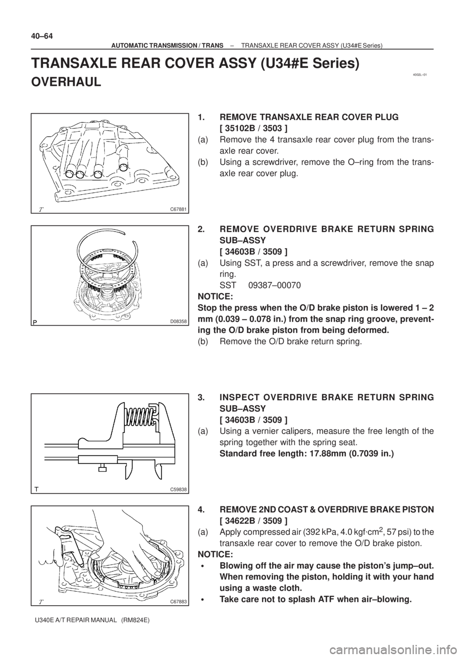
1. REMOVE TRANSAXLE REAR COVER PLUG
[ 35102B / 3503 ]
(a) Remove the 4 transaxle rear cover plug from the trans-
axle rear cover.
(b) Using a screwdriver, remove the O±ring from the trans-
axle rear cover plug.
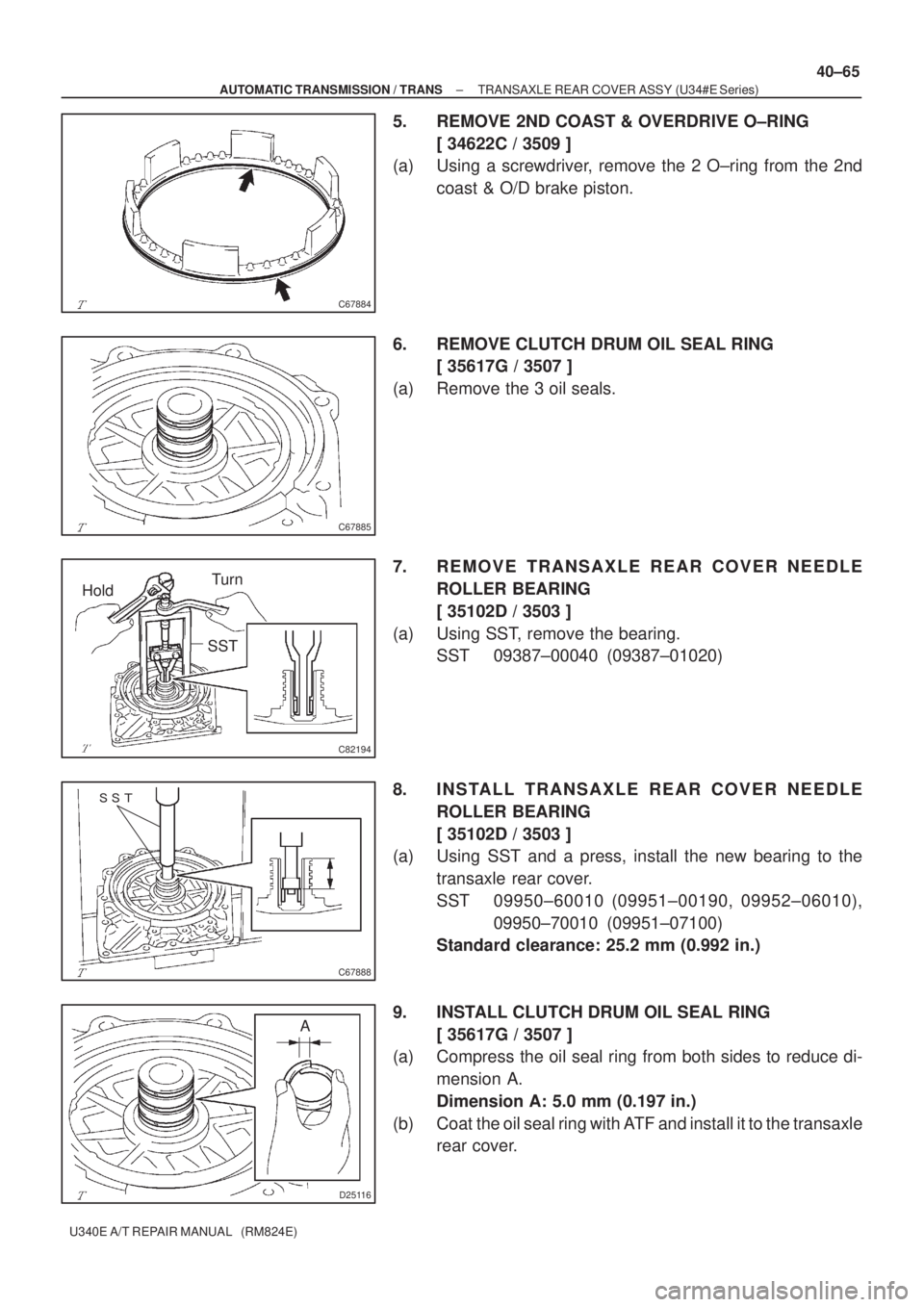
2. REMOVE OVERDRIVE BRAKE RETURN SPRING
SUB±ASSY
[ 34603B / 3509 ]
(a) Using SST, a press and a screwdriver, remove the snap
ring.
SST 09387±00070
NOTICE:
Stop the press when the O/D brake piston is lowered 1 ± 2
mm (0.039 ± 0.078 in.) from the snap ring groove, prevent-
ing the O/D brake piston from being deformed.
(b) Remove the O/D brake return spring.
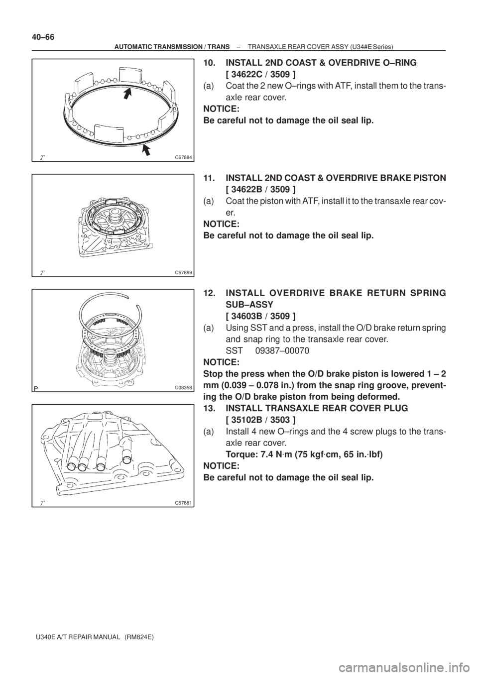
3. INSPECT OVERDRIVE BRAKE RETURN SPRING
SUB±ASSY
[ 34603B / 3509 ]
(a) Using a vernier calipers, measure the free length of the
spring together with the spring seat.
Standard free length: 17.88mm (0.7039 in.)
4. REMOVE 2ND COAST & OVERDRIVE BRAKE PISTON
[ 34622B / 3509 ]
(a) Apply compressed air (392 kPa, 4.0 kgf�cm
2, 57 psi) to the
transaxle rear cover to remove the O/D brake piston.
NOTICE:
�Blowing off the air may cause the piston's jump±out.
When removing the piston, holding it with your hand
using a waste cloth.
�Take care not to splash ATF when air±blowing.
Page 3605 of 5135

C67884
C67885
HoldTurn
SST
C82194
���
C67888
D25116
A
± AUTOMATIC TRANSMISSION / TRANSTRANSAXLE REAR COVER ASSY (U34#E Series)
40±65
U340E A/T REPAIR MANUAL (RM824E)
5. REMOVE 2ND COAST & OVERDRIVE O±RING
[ 34622C / 3509 ]
(a) Using a screwdriver, remove the 2 O±ring from the 2nd
coast & O/D brake piston.
6. REMOVE CLUTCH DRUM OIL SEAL RING
[ 35617G / 3507 ]
(a) Remove the 3 oil seals.
7. REMOVE TRANSAXLE REAR COVER NEEDLE
ROLLER BEARING
[ 35102D / 3503 ]
(a) Using SST, remove the bearing.
SST 09387±00040 (09387±01020)
8. INSTALL TRANSAXLE REAR COVER NEEDLE
ROLLER BEARING
[ 35102D / 3503 ]
(a) Using SST and a press, install the new bearing to the
transaxle rear cover.
SST 09950±60010 (09951±00190, 09952±06010),
09950±70010 (09951±07100)
Standard clearance: 25.2 mm (0.992 in.)
9. INSTALL CLUTCH DRUM OIL SEAL RING
[ 35617G / 3507 ]
(a) Compress the oil seal ring from both sides to reduce di-
mension A.
Dimension A: 5.0 mm (0.197 in.)
(b) Coat the oil seal ring with ATF and install it to the transaxle
rear cover.
Page 3606 of 5135

C67884
C67889
D08358
C67881
40±66
± AUTOMATIC TRANSMISSION / TRANSTRANSAXLE REAR COVER ASSY (U34#E Series)
U340E A/T REPAIR MANUAL (RM824E)
10. INSTALL 2ND COAST & OVERDRIVE O±RING
[ 34622C / 3509 ]
(a) Coat the 2 new O±rings with ATF, install them to the trans-
axle rear cover.
NOTICE:
Be careful not to damage the oil seal lip.
11. INSTALL 2ND COAST & OVERDRIVE BRAKE PISTON
[ 34622B / 3509 ]
(a) Coat the piston with ATF, install it to the transaxle rear cov-
er.
NOTICE:
Be careful not to damage the oil seal lip.
12. INSTALL OVERDRIVE BRAKE RETURN SPRING
SUB±ASSY
[ 34603B / 3509 ]
(a) Using SST and a press, install the O/D brake return spring
and snap ring to the transaxle rear cover.
SST 09387±00070
NOTICE:
Stop the press when the O/D brake piston is lowered 1 ± 2
mm (0.039 ± 0.078 in.) from the snap ring groove, prevent-
ing the O/D brake piston from being deformed.
13. INSTALL TRANSAXLE REAR COVER PLUG
[ 35102B / 3503 ]
(a) Install 4 new O±rings and the 4 screw plugs to the trans-
axle rear cover.
Torque: 7.4 N�m (75 kgf�cm, 65 in.�lbf)
NOTICE:
Be careful not to damage the oil seal lip.
Page 3629 of 5135
4006S±01
D03796
SST
C83462
D03824
C83463
± AUTOMATIC TRANSMISSION / TRANSSECOND BRAKE PISTON ASSY (U241E)
40±85
U241E A/T REPAIR MANUAL (RM840U)
SECOND BRAKE PISTON ASSY (U241E)
OVERHAUL
1. REMOVE 2ND BRAKE PISTON RETURN SPRING
SUB±ASSY
(a) Place SST on the return spring and compress.
SST 09387±00060
(b) Using a screwdriver, remove the snap ring.
(c) Remove the piston return spring.
2. INSPECT 2ND BRAKE PISTON RETURN SPRING
SUB±ASSY
(a) Using a vernier calipers, measure the free length of the
spring together with the spring seat.
Standard free length: 16.61 mm (0.6539 in.)
3. REMOVE 2ND BRAKE PISTON
(a) Hold the 2ND brake piston and apply compressed air (392
kPa, 4.0 kgf/cm
2, 57 psi) to the 2ND brake cylinder to re-
move the 2ND brake piston.
Page 3630 of 5135
C83465
C83465
C83464
C83462
D03796
SST
40±86
± AUTOMATIC TRANSMISSION / TRANSSECOND BRAKE PISTON ASSY (U241E)
U241E A/T REPAIR MANUAL (RM840U)
4. REMOVE 2ND BRAKE PISTON O±RING
(a) Remove the 2 O±rings from the 2ND brake piston.
5. INSTALL 2ND BRAKE PISTON O±RING
(a) Coat 2 new O±rings with ATF and install them in the 2ND
brake piston.
6. INSTALL 2ND BRAKE PISTON
(a) Press in the 2ND brake piston into the 2ND brake cylinder
with your hands.
7. INSTALL 2ND BRAKE PISTON RETURN SPRING
SUB±ASSY
(a) Install the piston return spring.
(b) Place SST on the piston return spring, and compress the
piston return spring with a press.
SST 09387±00060
(c) Using a screwdriver, install the snap ring.
NOTICE:
Be sure the end gap of the snap ring is not aligned with the
piston return spring claw.
Page 3640 of 5135
C83127
C83128
C83129
D03554
D03555
40±18
± AUTOMATIC TRANSMISSION / TRANSAUTOMATIC TRANSAXLE ASSY (U241E)
U241E A/T REPAIR MANUAL (RM840U)
16. REMOVE GOVERNOR APPLY GASKET NO.1
(a) Remove the governor apply gasket No. 1 from the trans-
axle case.
17. REMOVE TRANSAXLE CASE 2ND BRAKE GASKET
(a) Remove the transaxle case 2ND brake gasket from the
transaxle case.
18. REMOVE BRAKE DRUM GASKET
(a) Remove the brake drum gasket from the transaxle case.
19. REMOVE CHECK BALL BODY
(a) Remove the check ball body and spring from the trans-
axle case.
20. REMOVE C±3 ACCUMULATOR PISTON
(a) Remove the compression spring from the C
3 accumulator
piston.