Page 3657 of 5135

D03600
SST
D08061
D03800
D03913
D03811
± AUTOMATIC TRANSMISSION / TRANSAUTOMATIC TRANSAXLE ASSY (U241E)
40±35
U241E A/T REPAIR MANUAL (RM840U)
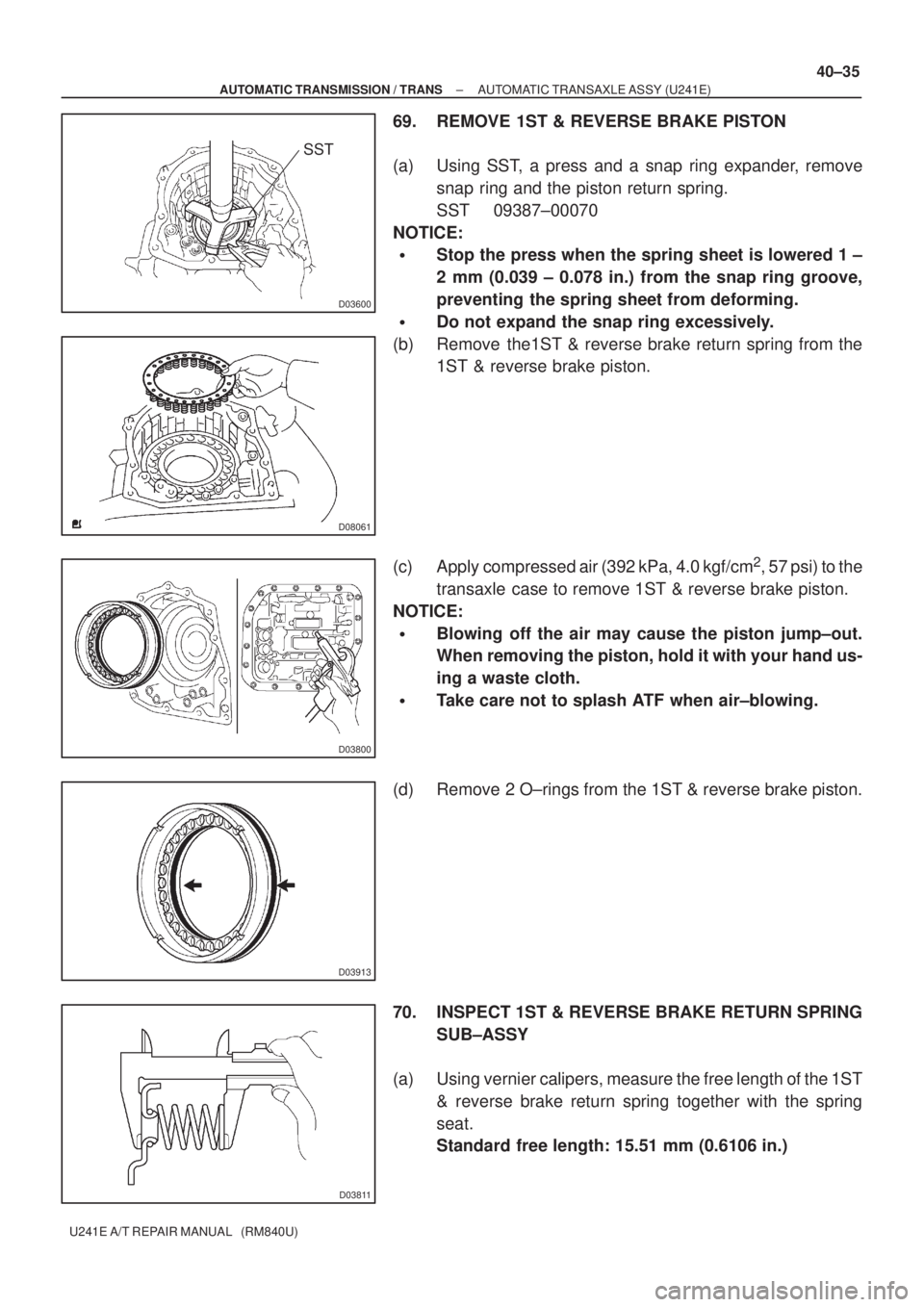
69. REMOVE 1ST & REVERSE BRAKE PISTON
(a) Using SST, a press and a snap ring expander, remove
snap ring and the piston return spring.
SST 09387±00070
NOTICE:
�Stop the press when the spring sheet is lowered 1 ±
2 mm (0.039 ± 0.078 in.) from the snap ring groove,
preventing the spring sheet from deforming.
�Do not expand the snap ring excessively.
(b) Remove the1ST & reverse brake return spring from the
1ST & reverse brake piston.
(c) Apply compressed air (392 kPa, 4.0 kgf/cm
2, 57 psi) to the
transaxle case to remove 1ST & reverse brake piston.
NOTICE:
�Blowing off the air may cause the piston jump±out.
When removing the piston, hold it with your hand us-
ing a waste cloth.
�Take care not to splash ATF when air±blowing.
(d) Remove 2 O±rings from the 1ST & reverse brake piston.
70. INSPECT 1ST & REVERSE BRAKE RETURN SPRING
SUB±ASSY
(a) Using vernier calipers, measure the free length of the 1ST
& reverse brake return spring together with the spring
seat.
Standard free length: 15.51 mm (0.6106 in.)
Page 3663 of 5135
D03613
SST
D03614
SST
D03913
D03813
D08072
± AUTOMATIC TRANSMISSION / TRANSAUTOMATIC TRANSAXLE ASSY (U241E)
40±41
U241E A/T REPAIR MANUAL (RM840U)
(b) Using SST and a press, install the tapered roller bearing
to the counter drive gear.
SST 09649±17010
NOTICE:
�Press±fit the bearing inner race until contacts the
counter drive gear.
�Do not apply excessive pressure to it.
(c) Using SST and a press, install the counter drive gear and
bearing to the transaxle case.
SST 09950±60020 (09951±00890), 09950±70010
(09951±07150)
NOTICE:
Do not apply excessive pressure to it.
80. INSTALL 1ST & REVERSE BRAKE PISTON
(a) Coat 2 new O±rings with ATF.
(b) Install the 2 O±ring to the 1st & reverse brake piston.
(c) Coat a 1st & reverse brake piston with ATF, install it to the
transaxle case.
(d) Install the 1st & reverse brake return spring to the 1st &
reverse brake piston.
Page 3664 of 5135
D03600
SST
D03615
D08063
D03916
SST
Counter Drive
GearTransaxle
Case
2nd Brake Hub
w/ Front Planetary
Gear Assy
40±42
± AUTOMATIC TRANSMISSION / TRANSAUTOMATIC TRANSAXLE ASSY (U241E)
U241E A/T REPAIR MANUAL (RM840U)
(e) Using SST, a press and snap ring expander, install the
piston return spring and snap ring to the transaxle case.
SST 09387±00070
NOTICE:
�Stop the press when the spring sheet is lowered to the
place 1 ± 2 mm (0.039 ± 0.078 in.) from the snap ring
groove, preventing the spring sheet from being de-
form.
�Do not expand the snap ring excessively.
81. INSTALL FRONT PLANETARY RING GEAR
(a) Using a screwdriver, install the front planetary ring gear
and brake hub snap ring to the brake hub.
82. INSTALL FRONT PLANETARY GEAR ASSY
(a) Install the front planetary gear assy to the brake hub.
(b) Using SST and a press, press±fit the front planetary gear
assy.
NOTICE:
Do not apply excessive pressure to it.
Page 3666 of 5135
D03873
D03593
D03910
D08062
D03616
40±44
± AUTOMATIC TRANSMISSION / TRANSAUTOMATIC TRANSAXLE ASSY (U241E)
U241E A/T REPAIR MANUAL (RM840U)
83. INSTALL INPUT SUN GEAR
(a) Install the 2 thrust bearings, the bearing race and the front
planetary sun gear to the front planetary gear assy.
Bearing and race diameter: mm (in.)
insideoutside
Bearing34.6 (1.362)52.2 (2.055)
Race40.3 (1.587)58.0 (2.283)
Bearing38.6 (1.520)60.0 (2.362)
84. INSTALL REAR PLANETARY GEAR ASSY
(a) Coat a bearing race with ATF, install it to the rear planetary
gear assy.
Bearing race diameter: mm (in.)
insideoutside
Race38.6 (1.520)58.0 (2.283)
(b) Install the planetary carrier thrust washer No. 2 to the
planetary gear assy.
(c) Install the rear planetary gear to the rear planetary ring
gear.
(d) Using a screwdriver, install the snap ring to the brake hub.
Page 3667 of 5135

D09190
D03618
A
D03815
D03619
± AUTOMATIC TRANSMISSION / TRANSAUTOMATIC TRANSAXLE ASSY (U241E)
40±45
U241E A/T REPAIR MANUAL (RM840U)
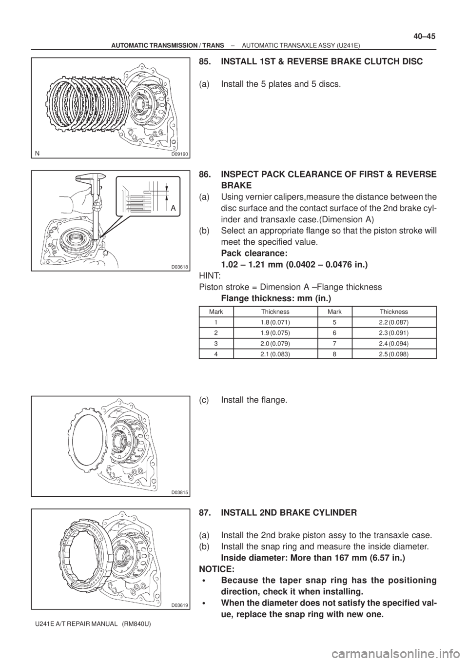
85. INSTALL 1ST & REVERSE BRAKE CLUTCH DISC
(a) Install the 5 plates and 5 discs.
86. INSPECT PACK CLEARANCE OF FIRST & REVERSE
BRAKE
(a) Using vernier calipers,measure the distance between the
disc surface and the contact surface of the 2nd brake cyl-
inder and transaxle case.(Dimension A)
(b) Select an appropriate flange so that the piston stroke will
meet the specified value.
Pack clearance:
1.02 ± 1.21 mm (0.0402 ± 0.0476 in.)
HINT:
Piston stroke = Dimension A ±Flange thickness
Flange thickness: mm (in.)
MarkThicknessMarkThickness
11.8 (0.071)52.2 (0.087)
21.9 (0.075)62.3 (0.091)
32.0 (0.079)72.4 (0.094)
42.1 (0.083)82.5 (0.098)
(c) Install the flange.
87. INSTALL 2ND BRAKE CYLINDER
(a) Install the 2nd brake piston assy to the transaxle case.
(b) Install the snap ring and measure the inside diameter.
Inside diameter: More than 167 mm (6.57 in.)
NOTICE:
�Because the taper snap ring has the positioning
direction, check it when installing.
�When the diameter does not satisfy the specified val-
ue, replace the snap ring with new one.
Page 3668 of 5135
D08078
D03909
D09638
Groove
Free
D03588
D03908
40±46
± AUTOMATIC TRANSMISSION / TRANSAUTOMATIC TRANSAXLE ASSY (U241E)
U241E A/T REPAIR MANUAL (RM840U)
88. INSTALL 1WAY CLUTCH SLEEVE OUTER
(a) Install the 1±way clutch outer sleeve to the 2nd brake cyl-
inder assy.
NOTICE:
Check the positioning direction of the outer sleeve.
89. INSTALL 1 WAY CLUTCH ASSY
(a) Install the inner race to the 1±way clutch.
NOTICE:
Check the direction of the inner race.
(b) Check the rotating direction of 1±way clutch for the lock
or free operation, as shown in illustration.
(c) Install the 1±way clutch and bearing to the 1±way clutch
outer race sleeve.
Bearing diameter: mm (in.)
InsideOutside
Bearing53.6 (2.110)69.6 (2.740)
NOTICE:
Install the thrust bearing properly so that no±colored race
will be visible.
90. INSTALL REAR PLANETARY SUN GEAR ASSY
(a) Coat the planetary carrier thrust washer No. 1 with petro-
leum jelly, install it onto the rear planetary sun gear.
Page 3669 of 5135

D03791
D03587
D09162
D09163
± AUTOMATIC TRANSMISSION / TRANSAUTOMATIC TRANSAXLE ASSY (U241E)
40±47
U241E A/T REPAIR MANUAL (RM840U)
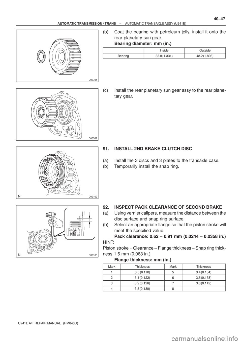
(b) Coat the bearing with petroleum jelly, install it onto the
rear planetary sun gear.
Bearing diameter: mm (in.)
InsideOutside
Bearing33.8 (1.331)48.2 (1.898)
(c) Install the rear planetary sun gear assy to the rear plane-
tary gear.
91. INSTALL 2ND BRAKE CLUTCH DISC
(a) Install the 3 discs and 3 plates to the transaxle case.
(b) Temporarily install the snap ring.
92. INSPECT PACK CLEARANCE OF SECOND BRAKE
(a) Using vernier calipers, measure the distance between the
disc surface and snap ring surface.
(b) Select an appropriate flange so that the piston stroke will
meet the specified value.
Pack clearance: 0.62 ± 0.91 mm (0.0244 ± 0.0358 in.)
HINT:
Piston stroke = Clearance ± Flange thickness ± Snap ring thick-
ness 1.6 mm (0.063 in.)
Flange thickness: mm (in.)
MarkThicknessMarkThickness
13.0 (0.118)53.4 (0.134)
23.1 (0.122)63.5 (0.138)
33.2 (0.126)73.6 (0.142)
43.3 (0.130)8±
Page 3671 of 5135

D03591
D03923
D03923
D25510
± AUTOMATIC TRANSMISSION / TRANSAUTOMATIC TRANSAXLE ASSY (U241E)
40±49
U241E A/T REPAIR MANUAL (RM840U)
NOTICE:
Make sure that the colored race side is facing the direct
clutch assy.
HINT:
End play = Dimension C ± Dimension B
Bearing thickness and diameter : mm (in.)
ThicknessInsideOutside
3.55 (0.1397)53.6 (2.110)69.6 (2.740)
3.85 (0.1515)53.6 (2.110)70.18 (2.763)
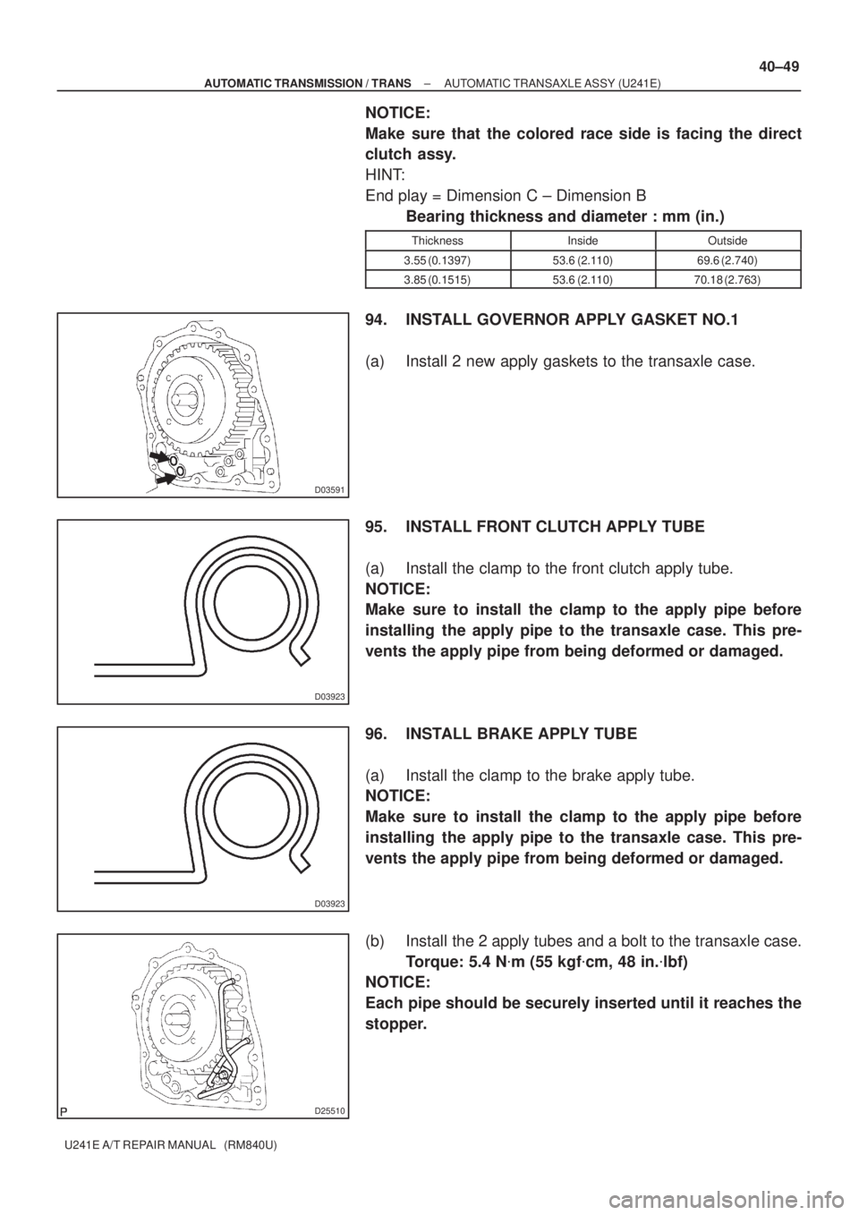
94. INSTALL GOVERNOR APPLY GASKET NO.1
(a) Install 2 new apply gaskets to the transaxle case.
95. INSTALL FRONT CLUTCH APPLY TUBE
(a) Install the clamp to the front clutch apply tube.
NOTICE:
Make sure to install the clamp to the apply pipe before
installing the apply pipe to the transaxle case. This pre-
vents the apply pipe from being deformed or damaged.
96. INSTALL BRAKE APPLY TUBE
(a) Install the clamp to the brake apply tube.
NOTICE:
Make sure to install the clamp to the apply pipe before
installing the apply pipe to the transaxle case. This pre-
vents the apply pipe from being deformed or damaged.
(b) Install the 2 apply tubes and a bolt to the transaxle case.
Torque: 5.4 N�m (55 kgf�cm, 48 in.�lbf)
NOTICE:
Each pipe should be securely inserted until it reaches the
stopper.