Page 3673 of 5135

D09946
FIPG
D09943A
D03914
D03809
Vinyl Tape
SST
D03810
SST
± AUTOMATIC TRANSMISSION / TRANSAUTOMATIC TRANSAXLE ASSY (U241E)
40±51
U241E A/T REPAIR MANUAL (RM840U)
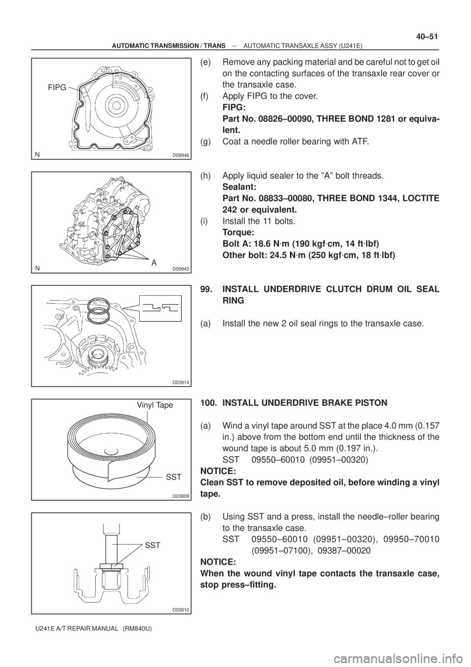
(e) Remove any packing material and be careful not to get oil
on the contacting surfaces of the transaxle rear cover or
the transaxle case.
(f) Apply FIPG to the cover.
FIPG:
Part No. 08826±00090, THREE BOND 1281 or equiva-
lent.
(g) Coat a needle roller bearing with ATF.
(h) Apply liquid sealer to the ºAº bolt threads.
Sealant:
Part No. 08833±00080, THREE BOND 1344, LOCTITE
242 or equivalent.
(i) Install the 11 bolts.
Torque:
Bolt A: 18.6 N�m (190 kgf�cm, 14 ft�lbf)
Other bolt: 24.5 N�m (250 kgf�cm, 18 ft�lbf)
99. INSTALL UNDERDRIVE CLUTCH DRUM OIL SEAL
RING
(a) Install the new 2 oil seal rings to the transaxle case.
100. INSTALL UNDERDRIVE BRAKE PISTON
(a) Wind a vinyl tape around SST at the place 4.0 mm (0.157
in.) above from the bottom end until the thickness of the
wound tape is about 5.0 mm (0.197 in.).
SST 09550±60010 (09951±00320)
NOTICE:
Clean SST to remove deposited oil, before winding a vinyl
tape.
(b) Using SST and a press, install the needle±roller bearing
to the transaxle case.
SST 09550±60010 (09951±00320), 09950±70010
(09951±07100), 09387±00020
NOTICE:
When the wound vinyl tape contacts the transaxle case,
stop press±fitting.
Page 3674 of 5135
D03794
D03609
D08071
D03610
SST
D09197
40±52
± AUTOMATIC TRANSMISSION / TRANSAUTOMATIC TRANSAXLE ASSY (U241E)
U241E A/T REPAIR MANUAL (RM840U)
(c) Coat 2 new O±rings with ATF, install them to the U/D
brake piston.
(d) Install the U/D brake piston to the transaxle case.
101. INSTALL UNDERDRIVE BRAKE RETURN SPRING
SUB±ASSY
(a) Install the U/D brake return spring to the U/D brake piston.
(b) Using SST, a snap ring expander and a press, install the
snap ring to the transaxle case.
SST 09387±00020
NOTICE:
Do not apply excessive pressure to it.
102. INSTALL UNDERDRIVE CLUTCH DISC NO.2
(a) Install the 3 discs and 3 plates to the transaxle case.
Page 3675 of 5135
D08050
D08082
D03907
D03925
Free
± AUTOMATIC TRANSMISSION / TRANSAUTOMATIC TRANSAXLE ASSY (U241E)
40±53
U241E A/T REPAIR MANUAL (RM840U)
(b) Using a screwdriver, install the snap ring.
(c) Using a dial indicator, measure the U/D brake piston
stroke while applying and releasing compressed air (392
kPa, 4.0 kgf/cm
2, 57 psi).
Piston stroke: 1.81 ± 2.20 mm (0.0713 ± 0.0866 in.)
HINT:
Select an appropriate flange from the table below so that it will
meet the specified value.
Flange thickness: mm (in.)
MarkThicknessMarkThickness
13.0 (0.118)33.4 (0.134)
23.2 (0.126)±±
(d) Temporally remove the snap ring and attach the flange.
Restore the snap ring.
103. INSTALL UNDERDRIVE 1 WAY CLUTCH ASSY
(a) Install the outer race retainer to the 1±way clutch.
(b) Install the U/D clutch assy to the 1±way clutch. Rotate the
U/D clutch assy to check the rotating direction for the lock
or free operation.
Page 3679 of 5135

D11358
Race ”B”
Race ”A”
Forward Clutch Side
D03574
D03573
C50035
D03569
−
AUTOMATIC TRANSMISSION / TRANS AUTOMATIC TRANSAXLE ASSY (U24
1E)
40− 57
Correction to R/M Pub. No. RM840U (Bulletin No. OB −1123)
108. INSTALL FORWARD CLUTCH ASSY
(a) Install the input shaft thrust bearing to the forward clutch.
Bearing diameter: mm (in.)
InsideOutside
Bearing33.85 ( 1.3327)52.2 (2.055)
NOTICE:
Install the thrust bearing properly so that the race ”B” will
be visible.
(b) Install the forward clutch to the multiple clutch hub.
NOTICE:
Align the splines of all discs in the forward clutch with
those of multiple clutch hub to assemble them securely.
109. INSTALL OVERDRIVE BRAKE GASKET
[35179 / 98− 3]
(a) Install 2 new O/D brake gaskets to the transaxle case.
11 0. INSTALL FRONNT DIFFERENTIAL ASSY
(a) Install the differential assy to the transaxle case.
111 . INSTALL OIL PUMP ASSEMBLY
(a) Install the oil pump assy and 7 bolts to the transaxle case.
Torque: 22 N ⋅m (226 kgf⋅cm, 16ft⋅lbf)
Page 3686 of 5135
C50009
C83129
C83128
C83127
D03553
A
C
A
C
�A
BB B�
C 40±64
± AUTOMATIC TRANSMISSION / TRANSAUTOMATIC TRANSAXLE ASSY (U241E)
U241E A/T REPAIR MANUAL (RM840U)
(b) Install the solenoid wire retaining bolt
Torque: 5.4 N�m (55 kgf�cm, 48 in.�lbf)
131. INSTALL BRAKE DRUM GASKET
(a) Coat a new brake drum gasket with ATF, install it to the
transaxle case.
132. INSTALL TRANSAXLE CASE 2ND BRAKE GASKET
(a) Coat a new transaxle case 2nd brake gasket with ATF,
install it to the transaxle case.
133. INSTALL GOVERNOR APPLY GASKET NO.1
(a) Coat a new governor apply gasket No. 1 with ATF, install
it to the transaxle case.
134. INSTALL TRANSMISSION VALVE BODY ASSY
(a) Make sure that the manual valve lever position, install the
valve body with 17 bolts to the transaxle case.
Torque: 11 N�m (110 kgf�cm, 8 ft�lbf)
Bolt length:
Bolt A: 25 mm (0.984 in.)
Bolt B: 41 mm (1.614 in.)
Bolt C: 45 mm (1.771 in.)
Page 3892 of 5135

± DIAGNOSTICSSFI SYSTEM (1AZ±FE)
05±157
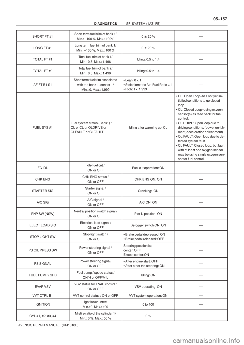
AVENSIS REPAIR MANUAL (RM1018E)SHORT FT #1
Short term fuel trim of bank 1/
Min.: ±100 %, Max.: 100%0 �20 %�
LONG FT #1Long term fuel trim of bank 1/
Min.: ±100 %, Max.: 100 %0 �20 %�
TOTAL FT #1Total fuel trim of bank 1/
Min.: 0.5, Max.: 1.496Idling: 0.5 to 1.4�
TOTAL FT #2Total fuel trim of bank 2/
Min.: 0.5, Max.: 1.496Idling: 0.5 to 1.4�
AF FT B1 S1
Short term fuel trim associated
with the bank 1, sensor 1/
Min.: 0, Max.: 1.999�Lean: 0 < 1
�Stoichiometric Air±Fuel Ratio = 1
�Rich: 1 < 1.999
�
FUEL SYS #1
Fuel system status (Bank1) /
OL or CL or OLDRIVE or
OLFAULT or CLFAULT
Idling after warming up: CL
�OL: Open Loop±has not yet sa-
tisfied conditions to go closed
loop.
�CL: Closed Loop±using oxygen
sensor(s) as feed back for fuel
control.
�OL DRIVE: Open loop due to
driving conditions. (power enrich-
ment, deceleration enleanment)
�OL FAULT: Open loop due to de-
tected system fault.
�CL FAULT: Closed loop, but fault
with at least one oxygen sensor
may be using single oxygen sen-
sor for fuel control.
FC IDLIdle fuel cut /
ON or OFFFuel cut operation: ON�
CHK ENGCHK ENG status /
ON or OFFCHK ENG ON: ON�
STARTER SIGStarter signal /
ON or OFFCranking: ON�
A/C SIGA/C signal /
ON or OFFA/C ON: ON�
PNP SW [NSW]Neutral position switch signal /
ON or OFFP or N position: ON�
ELECT LOAD SIGElectrical load signal /
ON or OFFDefogger switch ON: ON�
STOP LIGHT SWStop light switch /
ON or OFF�Brake pedal depressed: ON
�Brake pedal released: OFF�
PS OIL PRESS SWPower steering signal /
ON or OFFSteering position is;
center: OFF
Except center:ON
�
PS SIGNALPower steering signal/
ON or OFF�After engine start: OFF
�After steer the steering: ON�
FUEL PUMP / SPDFuel pump / speed status /
ON/H or OFF/M,LIdling: ON�
EVAP VSVVSV status for EVAP control /
ON or OFFVSV operating: ON�
VVT CTRL B1VVT control status / ON or OFFVVT system operation: ON�
IGNITIONIgnition counter/
Min.: 0, Max.: 4000 to 400�
CYL #1, #2, #3, #4Misfire ratio of the cylinder 1/
Min.: 0 %, Max.: 50 %0 %�
Page 3924 of 5135

±
DIAGNOSTICS SFI SYSTEM(1AZ±FSE)
05±475
AVENSIS REPAIR MANUAL (RM1018E)
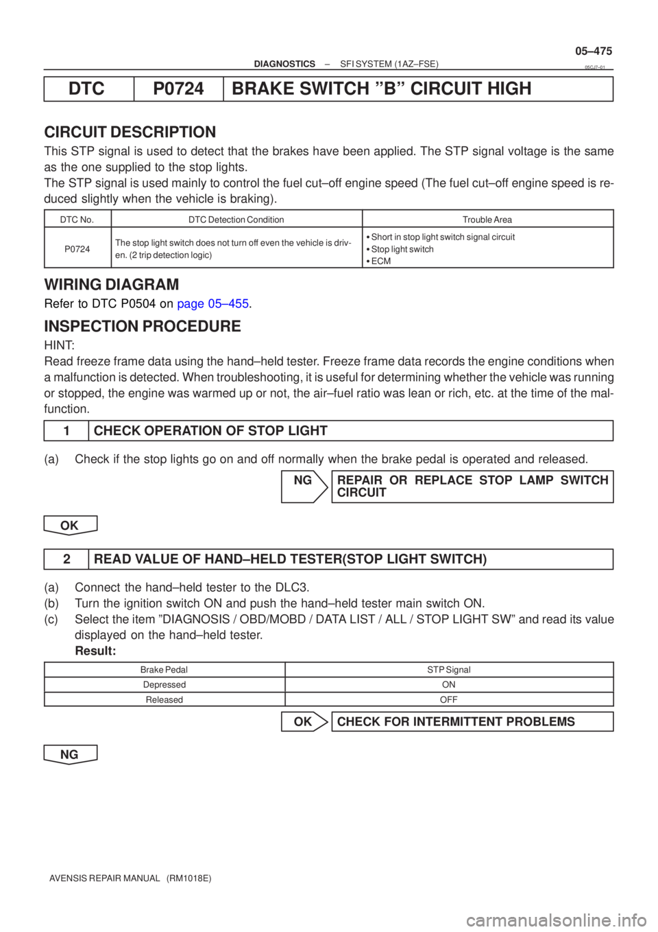
DTCP0724BRAKE SWITCH ºBº CIRCUIT HIGH
CIRCUIT DESCRIPTION
This STP signal is used to detect that the brakes have been applied. The STP\
signal voltage is the same
as the one supplied to the stop lights.
The STP signal is used mainly to control the fuel cut±off engine speed (The fuel cut±off engine speed is re-
duced slightly when the vehicle is braking).
DTC No.DTC Detection ConditionTrouble Area
P0724The stop light switch does not turn off even the vehicle is driv-
en. (2 trip detection logic)�Short in stop light switch signal circuit
� Stop light switch
� ECM
WIRING DIAGRAM
Refer to DTC P0504 on page 05±455.
INSPECTION PROCEDURE
HINT:
Read freeze frame data using the hand±held tester. Freeze frame data records the engine conditions when
a malfunction is detected. When troubleshooting, it is useful for determi\
ning whether the vehicle was running
or stopped, the engine was warmed up or not, the air±fuel ratio was lea\
n or rich, etc. at the time of the mal-
function.
1 CHECK OPERATION OF STOP LIGHT
(a) Check if the stop lights go on and off normally when the brake pedal is operated and released.
NG REPAIR OR REPLACE STOP LAMP SWITCHCIRCUIT
OK
2 READ VALUE OF HAND±HELD TESTER(STOP LIGHT SWITCH)
(a) Connect the hand±held tester to the DLC3.
(b) Turn the ignition switch ON and push the hand±held tester main switch \
ON.
(c) Select the item ºDIAGNOSIS / OBD/MOBD / DATA LIST / ALL / STOP LIGHT SWº and read its value displayed on the hand±held tester.
Result:
Brake PedalSTP Signal
DepressedON
ReleasedOFF
OK CHECK FOR INTERMITTENT PROBLEMS
NG
05CJ7±01
Page 3988 of 5135
05±840
± DIAGNOSTICSABS WITH EBD & BA & TRC & VSC SYSTEM
AVENSIS REPAIR MANUAL (RM1018E)
BRAKE WARNING LIGHT CIRCUIT
CIRCUIT DESCRIPTION
The Brake warning light comes on when the brake fluid is insufficient, the parking brake is applied or the EBD
is defective.
0543H±04