Page 3078 of 5135
610E8±01
B69710
± SEAT BELTFRONT SEAT BELT
61±5
AVENSIS REPAIR MANUAL (RM1018E)
FRONT SEAT BELT
PRECAUTION
CAUTION:
Replace the faulty parts of the seat belt systems (outer belt, inner belt, bolts, nuts, adjustable shoul-
der anchor, tether anchor hardware, sill±bar, etc.)
Seat belt systems not in use at the time of a collision should also be inspected and replaced if found
to be damaged or working improperly.
1. RUNNING TEST (IN SAFE AREA)
(a) Fasten the front seat belts.
(b) Drive the car at 16 km/h (10 mph) and slam on the brakes.
Check the belt locks and cannot be extended at this time.
HINT:
Conduct this test in a safe area. If the belt does not lock, remove
the belt assembly and perform the following static check. Also
whenever installing a new belt assembly, verify the proper op-
eration before installation.
Page 3237 of 5135
IG
SPEED
BKL SW
(D±seat)
BKL SW
(P seat)
WRN LAMP
BUZZERON
OFF
15km/h
0
BELT ON
BELT OFF
LVL1
LVL2 BELT ON
BELT OFF
ON
OFF OFF
30s
90s30s
90s
± INSTRUMENT PANEL/METERCOMBINATION METER
71±5
AVENSIS REPAIR MANUAL (RM1018E)
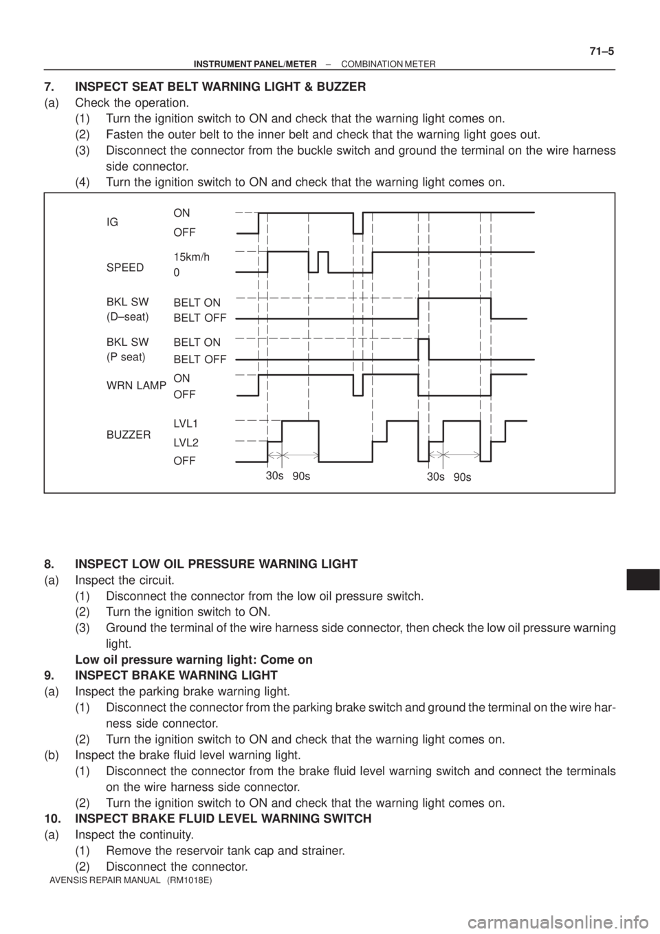
7. INSPECT SEAT BELT WARNING LIGHT & BUZZER
(a) Check the operation.
(1) Turn the ignition switch to ON and check that the warning light comes on.
(2) Fasten the outer belt to the inner belt and check that the warning light goes out.
(3) Disconnect the connector from the buckle switch and ground the terminal on the wire harness
side connector.
(4) Turn the ignition switch to ON and check that the warning light comes on.
8. INSPECT LOW OIL PRESSURE WARNING LIGHT
(a) Inspect the circuit.
(1) Disconnect the connector from the low oil pressure switch.
(2) Turn the ignition switch to ON.
(3) Ground the terminal of the wire harness side connector, then check the low oil pressure warning
light.
Low oil pressure warning light: Come on
9. INSPECT BRAKE WARNING LIGHT
(a) Inspect the parking brake warning light.
(1) Disconnect the connector from the parking brake switch and ground the terminal on the wire har-
ness side connector.
(2) Turn the ignition switch to ON and check that the warning light comes on.
(b) Inspect the brake fluid level warning light.
(1) Disconnect the connector from the brake fluid level warning switch and connect the terminals
on the wire harness side connector.
(2) Turn the ignition switch to ON and check that the warning light comes on.
10. INSPECT BRAKE FLUID LEVEL WARNING SWITCH
(a) Inspect the continuity.
(1) Remove the reservoir tank cap and strainer.
(2) Disconnect the connector.
Page 3239 of 5135
710CM±02
±
INSTRUMENT PANEL/METER COMBINATION METER
71±1
AVENSIS REPAIR MANUAL (RM1018E)
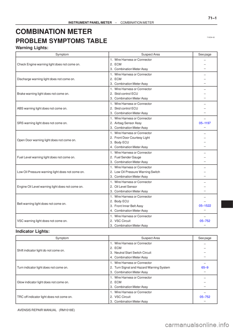
COMBINATION METER
PROBLEM SYMPTOMS TABLE
Warning Lights:
SymptomSuspect AreaSee page
Check Engine warning light does not come on.
1.Wire Harness or Connector
2.ECM
3.Combination Meter Assy±
±
±
Discharge warning light does not come on.
1.Wire Harness or Connector
2.ECM
3.Combination Meter Assy±
±
±
Brake warning light does not come on.
1.Wire Harness or Connector
2.Skid control ECU
3.Combination Meter Assy±
±
±
ABS warning light does not come on.
1.Wire Harness or Connector
2.Skid control ECU
3.Combination Meter Assy±
±
±
SRS warning light does not come on.
1.Wire Harness or Connector
2.Airbag Sensor Assy
3.Combination Meter Assy±
05±1197 ±
Open Door warning light does not come on.
1.Wire Harness or Connector
2.Front Door Courtesy Light
3.Body ECU
4.Combination Meter Assy±
±
±
±
Fuel Level warning light does not come on.
1.Wire Harness or Connector
2.Fuel Sender Gauge
3.Combination Meter Assy±
±
±
Low Oil Pressure warning light does not come on.
1.Wire Harness or Connector
2.Low Oil Pressure Warning Switch
3.Combination Meter Assy±
±
±
Engine Oil Level warning light does not come on.
1.Wire Harness or Connector
2.Oil Level Sensor
3.Combination Meter Assy±
±
±
Belt warning light does not come on.
1.Wire Harness or Connector
2.Body ECU
3.Front Inner Belt Assy
4.Combination Meter Assy±
±
05±1522
±
VSC warning light does not come on.
1.Wire Harness or Connector
2.VSC Circuit
3.Combination Meter Assy±
05±752 ±
Indicator Lights:
SymptomSuspect AreaSee page
Shift indicator light do not come on.
1. Wire Harness or Connector
2. ECM
3. Neutral Start Switch Circuit
4. Combination Meter Assy±
±
±
±
Turn indicator light does not come on.
1. Wire Harness or Connector
2. Turn Signal and Hazard Warning System
3. Combination Meter Assy±
65±9 ±
Glow indicator light does not come on.
1. Wire Harness or Connector
2. ECM
3. Combination Meter Assy±
±
±
TRC off indicator light does not come on.
1. Wire Harness or Connector
2. VSC Circuit
3. Combination Meter Assy±
05±752 ±
Page 3462 of 5135
010B9±09
± INTRODUCTIONTERMS
01±7
1AZ±FSE ENGINE REPAIR MANUAL (RM1019E)
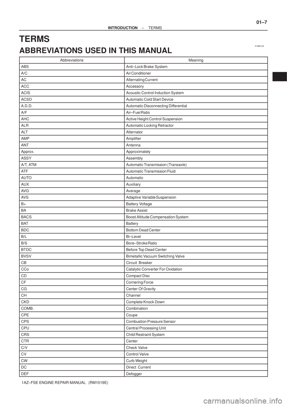
TERMS
ABBREVIATIONS USED IN THIS MANUAL
AbbreviationsMeaning
ABSAnti±Lock Brake System
A/CAir Conditioner
ACAlternating Current
ACCAccessory
ACISAcoustic Control Induction System
ACSDAutomatic Cold Start Device
A.D.D.Automatic Disconnecting Differential
A/FAir±Fuel Ratio
AHCActive Height Control Suspension
ALRAutomatic Locking Retractor
ALTAlternator
AMPAmplifier
ANTAntenna
Approx.Approximately
ASSYAssembly
A/T, ATMAutomatic Transmission (Transaxle)
AT FAutomatic Transmission Fluid
AUTOAutomatic
AUXAuxiliary
AV GAverage
AV SAdaptive Variable Suspension
B+Battery Voltage
BABrake Assist
BACSBoost Altitude Compensation System
BATBattery
BDCBottom Dead Center
B/LBi±Level
B/SBore±Stroke Ratio
BTDCBefore Top Dead Center
BVSVBimetallic Vacuum Switching Valve
CBCircuit Breaker
CCoCatalytic Converter For Oxidation
CDCompact Disc
CFCornering Force
CGCenter Of Gravity
CHChannel
CKDComplete Knock Down
COMB.Combination
CPECoupe
CPSCombustion Pressure Sensor
CPUCentral Processing Unit
CRSChild Restraint System
CTRCenter
C/VCheck Valve
CVControl Valve
CWCurb Weight
DCDirect Current
DEFDefogger
Page 3463 of 5135
01±8
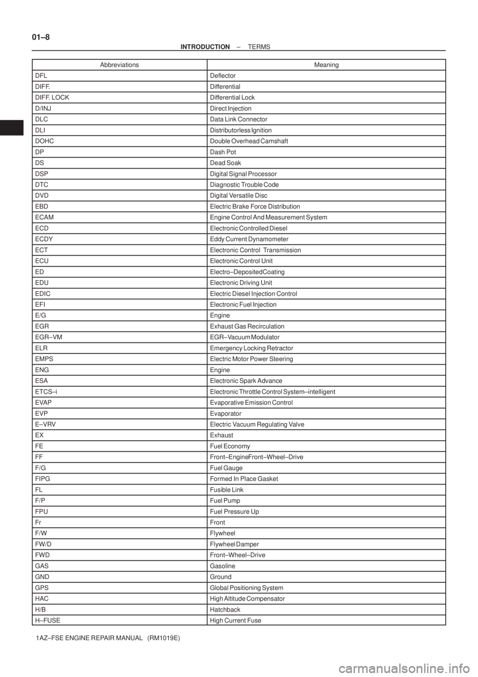
± INTRODUCTIONTERMS
1AZ±FSE ENGINE REPAIR MANUAL (RM1019E)Abbreviations Meaning
DFLDeflector
DIFF.Differential
DIFF. LOCKDifferential Lock
D/INJDirect Injection
DLCData Link Connector
DLIDistributorless Ignition
DOHCDouble Overhead Camshaft
DPDash Pot
DSDead Soak
DSPDigital Signal Processor
DTCDiagnostic Trouble Code
DVDDigital Versatile Disc
EBDElectric Brake Force Distribution
ECAMEngine Control And Measurement System
ECDElectronic Controlled Diesel
ECDYEddy Current Dynamometer
ECTElectronic Control Transmission
ECUElectronic Control Unit
EDElectro±Deposited Coating
EDUElectronic Driving Unit
EDICElectric Diesel Injection Control
EFIElectronic Fuel Injection
E/GEngine
EGRExhaust Gas Recirculation
EGR±VMEGR±Vacuum Modulator
ELREmergency Locking Retractor
EMPSElectric Motor Power Steering
ENGEngine
ESAElectronic Spark Advance
ETCS±iElectronic Throttle Control System±intelligent
EVAPEvaporative Emission Control
EVPEvaporator
E±VRVElectric Vacuum Regulating Valve
EXExhaust
FEFuel Economy
FFFront±Engine Front±Wheel±Drive
F/GFuel Gauge
FIPGFormed In Place Gasket
FLFusible Link
F/PFuel Pump
FPUFuel Pressure Up
FrFront
F/WFlywheel
FW/DFlywheel Damper
FWDFront±Wheel±Drive
GASGasoline
GNDGround
GPSGlobal Positioning System
HACHigh Altitude Compensator
H/BHatchback
H±FUSEHigh Current Fuse
Page 3465 of 5135
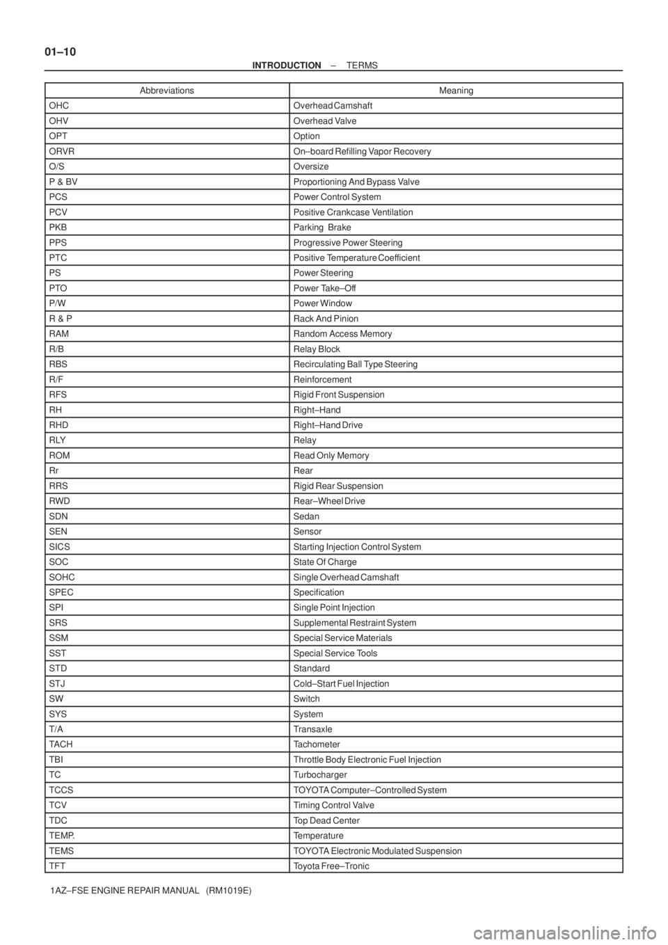
01±10
± INTRODUCTIONTERMS
1AZ±FSE ENGINE REPAIR MANUAL (RM1019E)Abbreviations Meaning
OHCOverhead Camshaft
OHVOverhead Valve
OPTOption
ORVROn±board Refilling Vapor Recovery
O/SOversize
P & BVProportioning And Bypass Valve
PCSPower Control System
PCVPositive Crankcase Ventilation
PKBParking Brake
PPSProgressive Power Steering
PTCPositive Temperature Coefficient
PSPower Steering
PTOPower Take±Off
P/WPower Window
R & PRack And Pinion
RAMRandom Access Memory
R/BRelay Block
RBSRecirculating Ball Type Steering
R/FReinforcement
RFSRigid Front Suspension
RHRight±Hand
RHDRight±Hand Drive
RLYRelay
ROMRead Only Memory
RrRear
RRSRigid Rear Suspension
RWDRear±Wheel Drive
SDNSedan
SENSensor
SICSStarting Injection Control System
SOCState Of Charge
SOHCSingle Overhead Camshaft
SPECSpecification
SPISingle Point Injection
SRSSupplemental Restraint System
SSMSpecial Service Materials
SSTSpecial Service Tools
STDStandard
STJCold±Start Fuel Injection
SWSwitch
SYSSystem
T/ATransaxle
TACHTachometer
TBIThrottle Body Electronic Fuel Injection
TCTurbocharger
TCCSTOYOTA Computer±Controlled System
TCVTiming Control Valve
TDCTop Dead Center
TEMP.Temperature
TEMSTOYOTA Electronic Modulated Suspension
TFTToyota Free±Tronic
Page 3582 of 5135
4002J±01
D03796
SST
C67862
C67865
C67863
40±56
± AUTOMATIC TRANSMISSION / TRANSSECOND BRAKE PISTON ASSY (U34#E Series)
U340E A/T REPAIR MANUAL (RM824E)
SECOND BRAKE PISTON ASSY (U34#E Series)
OVERHAUL
1. REMOVE 2ND BRAKE PISTON RETURN SPRING
SUB±ASSY
[ 35608L / 3509 ]
(a) Place SST on the piston return spring and compress.
SST 09387±00060
(b) Using a screwdriver, remove the snap ring.
(c) Remove the 2nd brake return spring from the 2nd brake
cylinder.
2. INSPECT 2ND BRAKE PISTON RETURN SPRING
SUB±ASSY
[ 35608L / 3509 ]
(a) Using vernier calipers, measure the free length of the
spring together with the spring seat.
Standard free length: 14.65 mm (0.5768 in.)
3. REMOVE 2ND BRAKE PISTON
[ 35624E / 3509 ]
(a) Hold the 2nd brake piston and apply compressed air (392
kPa, 4.0 kgf�cm
2, 57 psi) to the 2nd brake cylinder to re-
move the 2nd brake piston.
Page 3583 of 5135
C67864
C67864
C67866
C67862
D03796
SST
± AUTOMATIC TRANSMISSION / TRANSSECOND BRAKE PISTON ASSY (U34#E Series)
40±57
U340E A/T REPAIR MANUAL (RM824E)
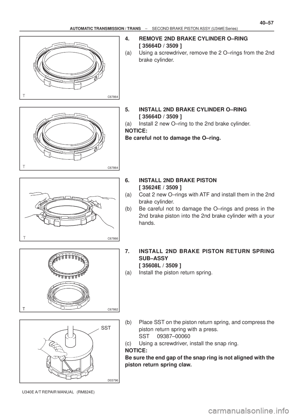
4. REMOVE 2ND BRAKE CYLINDER O±RING
[ 35664D / 3509 ]
(a) Using a screwdriver, remove the 2 O±rings from the 2nd
brake cylinder.
5. INSTALL 2ND BRAKE CYLINDER O±RING
[ 35664D / 3509 ]
(a) Install 2 new O±ring to the 2nd brake cylinder.
NOTICE:
Be careful not to damage the O±ring.
6. INSTALL 2ND BRAKE PISTON
[ 35624E / 3509 ]
(a) Coat 2 new O±rings with ATF and install them in the 2nd
brake cylinder.
(b) Be careful not to damage the O±rings and press in the
2nd brake piston into the 2nd brake cylinder with a your
hands.
7. INSTALL 2ND BRAKE PISTON RETURN SPRING
SUB±ASSY
[ 35608L / 3509 ]
(a) Install the piston return spring.
(b) Place SST on the piston return spring, and compress the
piston return spring with a press.
SST 09387±00060
(c) Using a screwdriver, install the snap ring.
NOTICE:
Be sure the end gap of the snap ring is not aligned with the
piston return spring claw.