Page 2750 of 5135
4011J±01
C98999
C98999
± AUTOMATIC TRANSMISSION / TRANSSHIFT LOCK SYSTEM
40±59
AVENSIS REPAIR MANUAL (RM1018E)
SHIFT LOCK SYSTEM
ON±VEHICLE INSPECTION
1. CHECK SHIFT LOCK OPERATION
(a) Shift the shift lever to P position.
(b) Turn the ignition switch to LOCK.
(c) Check that the shift lever cannot be shifted to any other positions other than P.
(d) Turn the ignition switch to ON, depress the brake pedal and check that the shift lever can be shifted
to any other positions.
2. CHECK SHIFT LOCK RELEASE BUTTON OPERATION
(a) Using a screwdriver, remove the shift lock release button cover.
(b) When operating the shift lever with the shift lock release button pressed and turn the ignition switch
to ACC or ON, check that the lever can be shifted to any other position.
3. CHECK KEY INTERLOCK OPERATION
(a) Turn the ignition switch to ON.
(b) Depress the brake pedal and shift the shift lever to any other positions other than P.
(c) Check that the ignition key cannot be turned to LOCK.
(d) Shift the shift lever to P position, turn the ignition key to LOCK and check that the ignition key can be
removed.
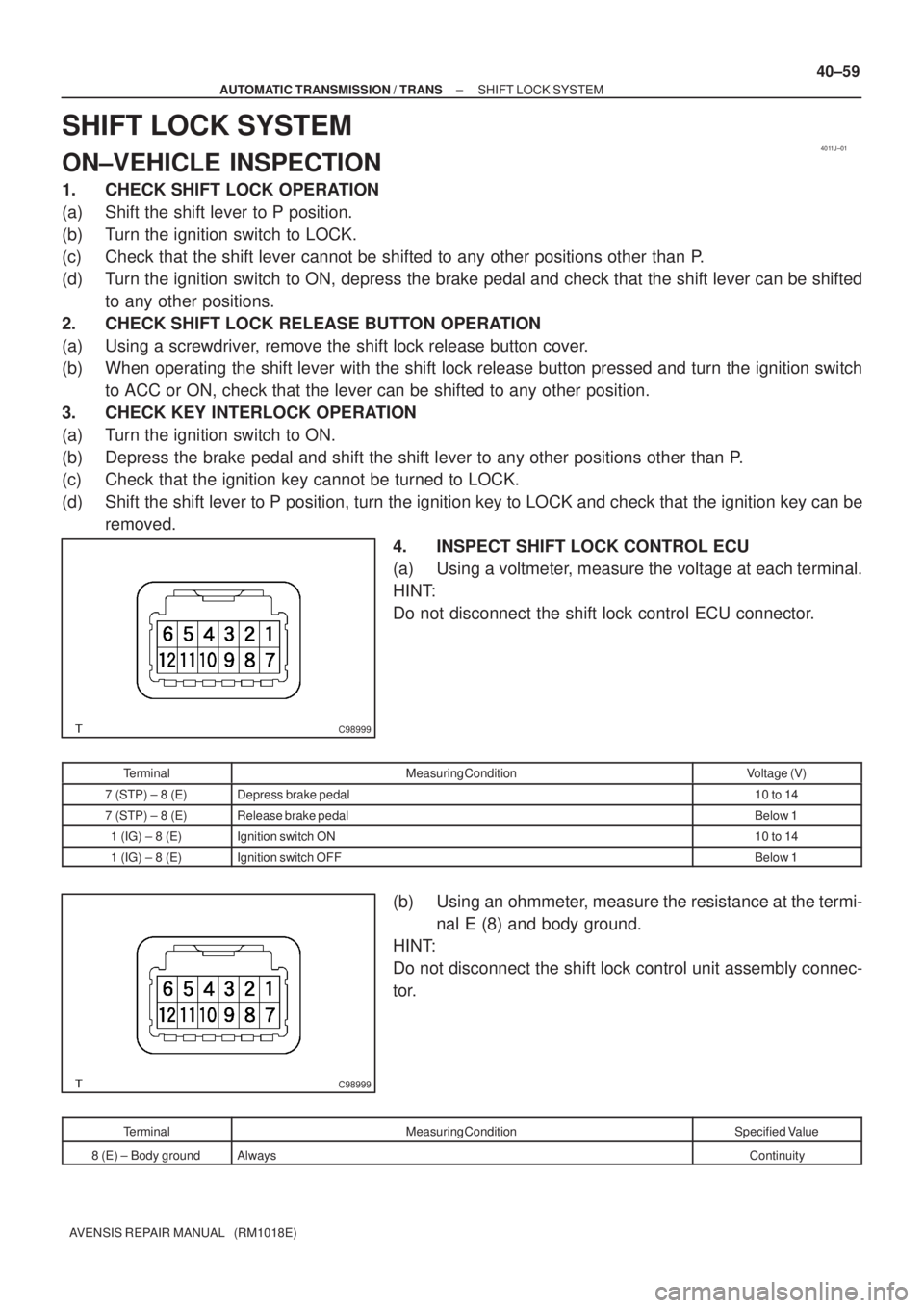
4. INSPECT SHIFT LOCK CONTROL ECU
(a) Using a voltmeter, measure the voltage at each terminal.
HINT:
Do not disconnect the shift lock control ECU connector.
TerminalMeasuring ConditionVoltage (V)
7 (STP) ± 8 (E)Depress brake pedal10 to 14
7 (STP) ± 8 (E)Release brake pedalBelow 1
1 (IG) ± 8 (E)Ignition switch ON10 to 14
1 (IG) ± 8 (E)Ignition switch OFFBelow 1
(b) Using an ohmmeter, measure the resistance at the termi-
nal E (8) and body ground.
HINT:
Do not disconnect the shift lock control unit assembly connec-
tor.
TerminalMeasuring ConditionSpecified Value
8 (E) ± Body groundAlwaysContinuity
Page 2755 of 5135
4206E±01
D30068
D30069
SST(s)
D30782
RHD Steering Position Type:
LHD Steering Position Type:
±
CLUTCH CLUTCH MASTER CYLINDER ASSY (MTM)
42±13
AVENSIS REPAIR MANUAL (RM1018E)
REPLACEMENT
1. DRAIN CLUTCH FLUID
2. REMOVE BRAKE MASTER CYLINDER SUB±ASSY (LHD STEERING POSITION TYPE)
(See page 32±13)
3.REMOVE BRAKE BOOSTER ASSY (LHD STEERING POSITION TYPE) (See page 32±19)
4. DISCONNECT CLUTCH RESERVOIR TUBE
(a) Loosen the clip and disconnect the clutch reservoir tubefrom the clutch master cylinder assy.
HINT:
Use a container to catch the fluid.
5. DISCONNECT CLUTCH MASTER CYLINDER TO FLEXIBLE HOSE TUBE
(a) Using SST(s), disconnect the flexible hose tube. SST 09023±00100
HINT:
Use a container to catch the fluid.
6. REMOVE CLUTCH MASTER CYLINDER PUSH ROD
CLEVIS W/HOLE PIN
(a) Remove the clip and hole pin.
Page 2756 of 5135
D30782
RHD Steering Position Type:
LHD Steering Position Type:
MP Grease
D30069
SST(s)
D30068
Blue Mark
42±14
±
CLUTCH CLUTCH MASTER CYLINDER ASSY (MTM)
AVENSIS REPAIR MANUAL (RM1018E)
7. REMOVE CLUTCH MASTER CYLINDER ASSY
(a) Remove the 2 nuts clutch master cylinder assy and gasket.
8. INSTALL CLUTCH MASTER CYLINDER ASSY
(a) Install the clutch master cylinder assy and gasket with the 2 nuts. Torque: 12 N �m (120 kgf �cm, 9 ft �lbf)
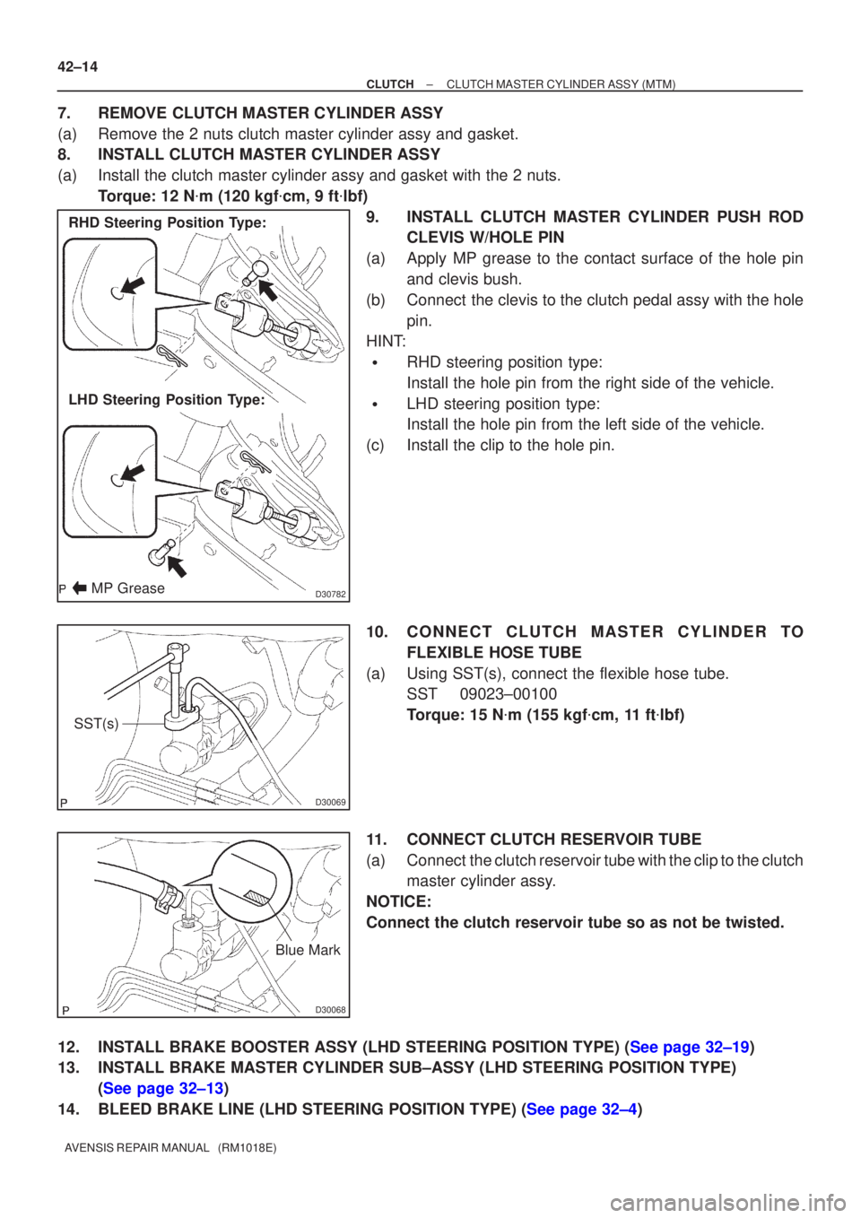
9. INSTALL CLUTCH MASTER CYLINDER PUSH ROD CLEVIS W/HOLE PIN
(a) Apply MP grease to the contact surface of the hole pin and clevis bush.
(b) Connect the clevis to the clutch pedal assy with the hole pin.
HINT:
�RHD steering position type:
Install the hole pin from the right side of the vehicle.
�LHD steering position type:
Install the hole pin from the left side of the vehicle.
(c) Install the clip to the hole pin.
10. CONNECT CLUTCH MASTER CYLINDER TO FLEXIBLE HOSE TUBE
(a) Using SST(s), connect the flexible hose tube. SST 09023±00100
Torque: 15 N �m (155 kgf �cm, 11 ft �lbf)
11. CONNECT CLUTCH RESERVOIR TUBE
(a) Connect the clutch reservoir tube with the clip to the clutch master cylinder assy.
NOTICE:
Connect the clutch reservoir tube so as not be twisted.
12.INSTALL BRAKE BOOSTER ASSY (LHD STEERING POSITION TYPE) (See page 32±19)
13. INSTALL BRAKE MASTER CYLINDER SUB±ASSY (LHD STEERING POSITION TYPE) (See page 32±13)
14.BLEED BRAKE LINE (LHD STEERING POSITION TYPE) (See page 32±4)
Page 2757 of 5135
±
CLUTCH CLUTCH MASTER CYLINDER ASSY (MTM)
42±15
AVENSIS REPAIR MANUAL (RM1018E)
15. BLEED CLUTCH PIPE LINE
(a) Fill the brake reservoir tank with the clutch fluid and bleed clutch sys\
tem.
Torque: 8.4 N �m (85 kgf �cm, 73 in. �lbf)
16. CHECK AND ADJUST BRAKE PEDAL HEIGHT (LHD STEERING POSITION TYPE) (See page 32±6)
17.INSPECT AND ADJUST CLUTCH PEDAL SUB±ASSY (See page 42±2)
18. CHECK BRAKE FLUID LEAKAGE (LHD STEERING POSITION TYPE)
19. CHECK CLUTCH FLUID LEAKAGE
20. CHECK FLUID LEVEL IN RESERVOIR
Page 2768 of 5135
CL0102Pedal Free Play
CL0512
25 mm (0.98 in.) or more
Release Point
Full Stroke
End Position
± CLUTCHCLUTCH PEDAL SUB±ASSY (MTM)
42±3
AVENSIS REPAIR MANUAL (RM1018E)
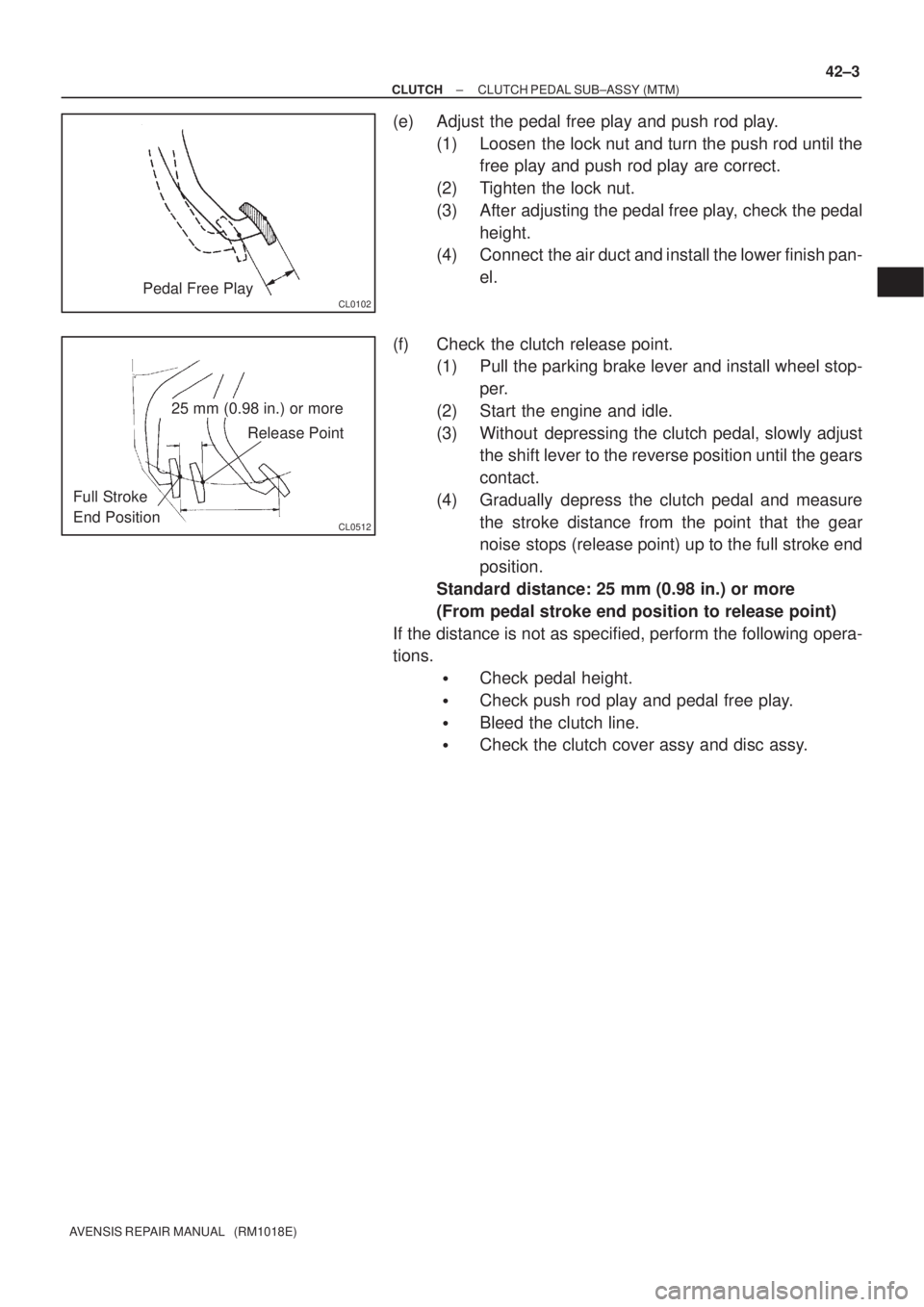
(e) Adjust the pedal free play and push rod play.
(1) Loosen the lock nut and turn the push rod until the
free play and push rod play are correct.
(2) Tighten the lock nut.
(3) After adjusting the pedal free play, check the pedal
height.
(4) Connect the air duct and install the lower finish pan-
el.
(f) Check the clutch release point.
(1) Pull the parking brake lever and install wheel stop-
per.
(2) Start the engine and idle.
(3) Without depressing the clutch pedal, slowly adjust
the shift lever to the reverse position until the gears
contact.
(4) Gradually depress the clutch pedal and measure
the stroke distance from the point that the gear
noise stops (release point) up to the full stroke end
position.
Standard distance: 25 mm (0.98 in.) or more
(From pedal stroke end position to release point)
If the distance is not as specified, perform the following opera-
tions.
�Check pedal height.
�Check push rod play and pedal free play.
�Bleed the clutch line.
�Check the clutch cover assy and disc assy.
Page 2830 of 5135
4206G±01
D30813
(a)
(a) (b)(b)
(a)
(b)
D30813
(a)
(a) (b)(b)
(a)
(b)
D26852
SST(s)
42±22
±
CLUTCH CLUTCH ACCUMULATOR ASSY (1CD±FTV)
AVENSIS REPAIR MANUAL (RM1018E)
REPLACEMENT
1. REMOVE BATTERY
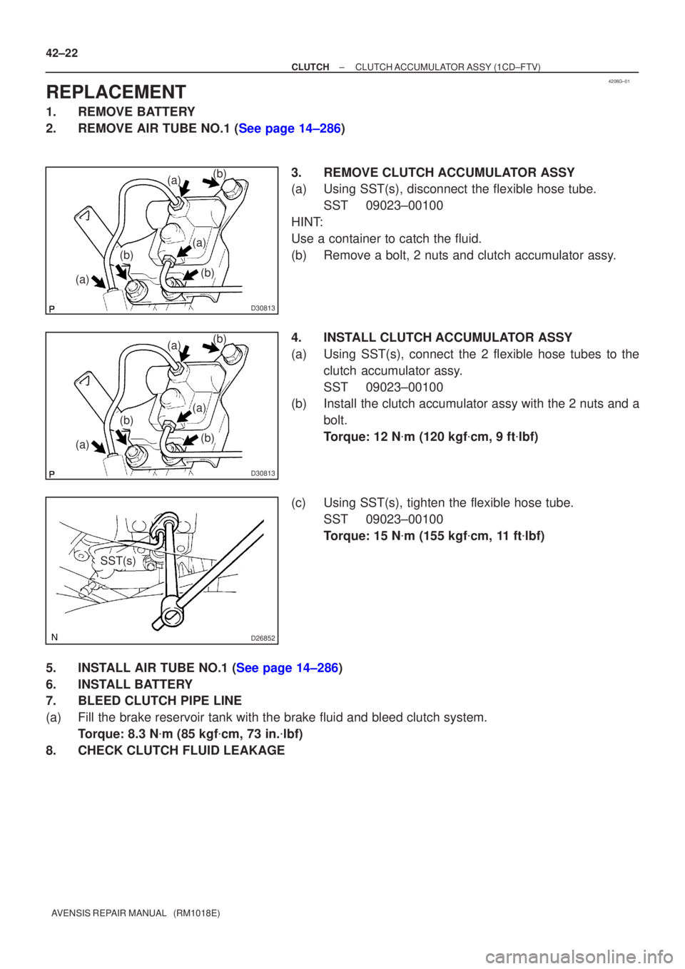
2.REMOVE AIR TUBE NO.1 (See page 14±286) 3. REMOVE CLUTCH ACCUMULATOR ASSY
(a) Using SST(s), disconnect the flexible hose tube.SST 09023±00100
HINT:
Use a container to catch the fluid.
(b) Remove a bolt, 2 nuts and clutch accumulator assy.
4. INSTALL CLUTCH ACCUMULATOR ASSY
(a) Using SST(s), connect the 2 flexible hose tubes to the clutch accumulator assy.
SST 09023±00100
(b) Install the clutch accumulator assy with the 2 nuts and a
bolt.
Torque: 12 N �m (120 kgf �cm, 9 ft �lbf)
(c) Using SST(s), tighten the flexible hose tube. SST 09023±00100
Torque: 15 N �m (155 kgf �cm, 11 ft �lbf)
5.INSTALL AIR TUBE NO.1 (See page 14±286)
6. INSTALL BATTERY
7. BLEED CLUTCH PIPE LINE
(a) Fill the brake reservoir tank with the brake fluid and bleed clutch syst\
em. Torque: 8.3 N �m (85 kgf �cm, 73 in. �lbf)
8. CHECK CLUTCH FLUID LEAKAGE
Page 2835 of 5135
D30814
D30487
SST(s)
1ZZ±FE/3ZZ±FE Engine Type:
1AZ±FE/1AZ±FSE Engine Type:SST(s)
42±20
±
CLUTCH CLUTCH RELEASE CYLINDER ASSY (MTM)
AVENSIS REPAIR MANUAL (RM1018E)
13. INSTALL CLUTCH ACCUMULATOR ASSY (1CD±FTV ENGINE TYPE)
(a) Install the clutch accumulator assy with the 2 nuts and
bolt.
Torque: 12 N �m (120 kgf �cm, 9 ft �lbf)
(b) Using SST(s), connect the 2 flexible hose tubes. SST 09023±00100
Torque: 15 N �m (155 kgf �cm, 11 ft �lbf)
(c) Connect the wire harness clamp.
14. CONNECT CLUTCH RELEASE CYLINDER TO FLEXIBLE HOSE TUBE (EXCEPT 1CD±FTV ENGINE
TYPE)
(a) Using SST(s), connect the flexible hose tube. SST 09023±00100
Torque: 15 N �m (155 kgf �cm, 11 ft �lbf)
15.INSTALL AIR TUBE NO.1 (1CD±FTV ENGINE TYPE) (See page 14±286)
16. INSTALL BATTERY (1CD±FTV ENGINE TYPE)
17. BLEED CLUTCH PIPE LINE
(a) Fill the brake reservoir tank with the brake fluid and bleed clutch syst\
em. Torque: 8.3 N �m (85 kgf �cm, 73 in. �lbf)
18. CHECK CLUTCH FLUID LEAKAGE
Page 2839 of 5135
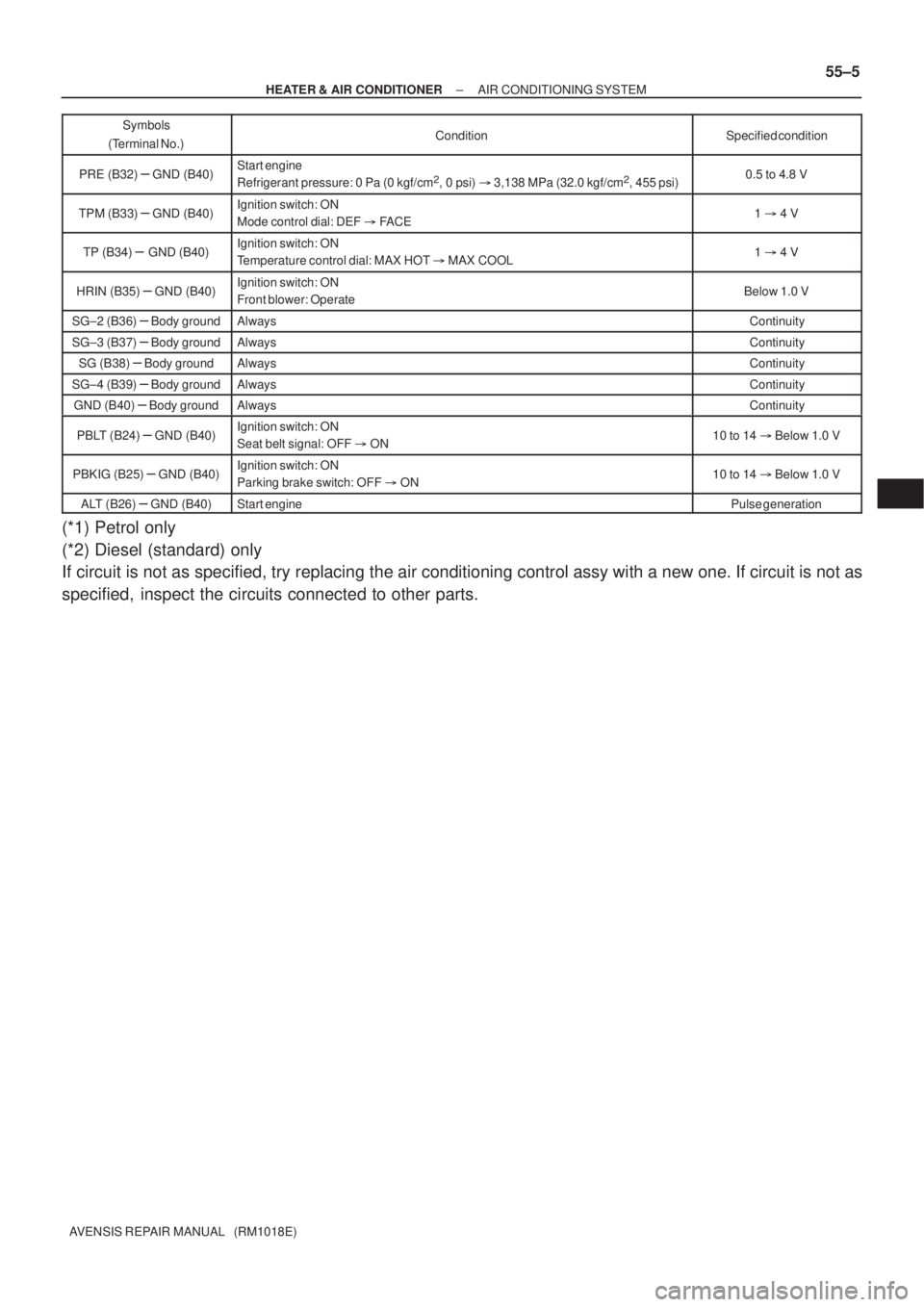
± HEATER & AIR CONDITIONERAIR CONDITIONING SYSTEM
55±5
AVENSIS REPAIR MANUAL (RM1018E)Symbols
(Terminal No.)Specified condition Condition
PRE (B32) ± GND (B40)Start engine
Refrigerant pressure: 0 Pa (0 kgf/cm2, 0 psi) � 3,138 MPa (32.0 kgf/cm2, 455 psi)0.5 to 4.8 V
TPM (B33) ± GND (B40)Ignition switch: ON
Mode control dial: DEF � FACE1 � 4 V
TP (B34) ± GND (B40)Ignition switch: ON
Temperature control dial: MAX HOT � MAX COOL1 � 4 V
HRIN (B35) ± GND (B40)Ignition switch: ON
Front blower: OperateBelow 1.0 V
SG±2 (B36) ± Body groundAlwaysContinuity
SG±3 (B37) ± Body groundAlwaysContinuity
SG (B38) ± Body groundAlwaysContinuity
SG±4 (B39) ± Body groundAlwaysContinuity
GND (B40) ± Body groundAlwaysContinuity
PBLT (B24) ± GND (B40)Ignition switch: ON
Seat belt signal: OFF � ON10 to 14 � Below 1.0 V
PBKIG (B25) ± GND (B40)Ignition switch: ON
Parking brake switch: OFF � ON10 to 14 � Below 1.0 V
ALT (B26) ± GND (B40)Start enginePulse generation
(*1) Petrol only
(*2) Diesel (standard) only
If circuit is not as specified, try replacing the air conditioning control assy with a new one. If circuit is not as
specified, inspect the circuits connected to other parts.