Page 2639 of 5135
C80805
C82119
C81275
C81274
F45367
± BRAKEBRAKE BOOSTER ASSY (RHD)
32±29
AVENSIS REPAIR MANUAL (RM1018E)
18. INSTALL BRAKE BOOSTER ASSY
(a) Install the clevis to the booster push rod.
(b) Install the brake booster assy with the 4 nuts.
Torque: 13 N�m (130 kgf�cm, 9 ft�lbf)
(c) Connect the vacuum hose to the check valve.
(d) Install the engine mounting bracket RH to the body with
the 3 bolts.
Torque: 52 N�m (530 kgf�cm, 39 ft�lbf)
(e) Install the bolt to the rear engine mounting bracket.
Torque: 87 N�m (887 kgf�cm, 64 ft�lbf)
(f) Install the bolt and nut to the front engine mounting brack-
et.
Torque: 52 N�m (530 kgf�cm, 39 ft�lbf)
(g) Install the 2 nuts to the engine mounting bracket RH.
Torque: 52 N�m (530 kgf�cm, 39 ft�lbf)
(h) Install the engine under cover.
(i) Connect the vacuum hose to the brake booster assy.
(j) Gasoline engine type:
Install the vacuum pipe with 2 bolts to the body.
Torque: 5.4 N�m (55 kgf�cm, 48 in.�lbf)
Page 2640 of 5135
F45363Vacuum tank
F45362
F45361
C80802
32±30
± BRAKEBRAKE BOOSTER ASSY (RHD)
AVENSIS REPAIR MANUAL (RM1018E)
(k) Diesel engine type:
Install the vacuum tank with 2 bolts.
Torque: 8.3 N�m (85 kgf�cm, 73 in.�lbf)
19. INSTALL BRAKE TUBE
(a) Disconnect the 3 brake tubes from the clamp and remove
the brake tubes.
(b) Using SST, connect the 3 brake tubes to the ways.
SST 09023±00100
Torque: 15 N�m (155 kgf�cm, 11 ft�lbf)
(c) Connect the brake tube to the clamp.
(d) Using SST and a spanner, connect the brake tube to the
flexible hose of front brake RH.
SST 09023±00100
Torque: 15 N�m (155 kgf�cm, 11 ft�lbf)
Page 2641 of 5135
F45057
w/o VSC:
w/ VSC:
To Master
Cylinder Rear
To
Master
Cylinder
Front
To Rear Wheel
RH
To Front Wheel LH
To Front Wheel RH
To Rear Wheel
LH
A
To
Master
Cylinder
FrontTo Master
Cylinder
Rear
To Rear
Wheel RH
To Front Wheel LHTo Front Wheel RH
To Rear
Wheel LH
AA
AA
BB
C80806
±
BRAKE BRAKE BOOSTER ASSY (RHD)
32±31
AVENSIS REPAIR MANUAL (RM1018E)
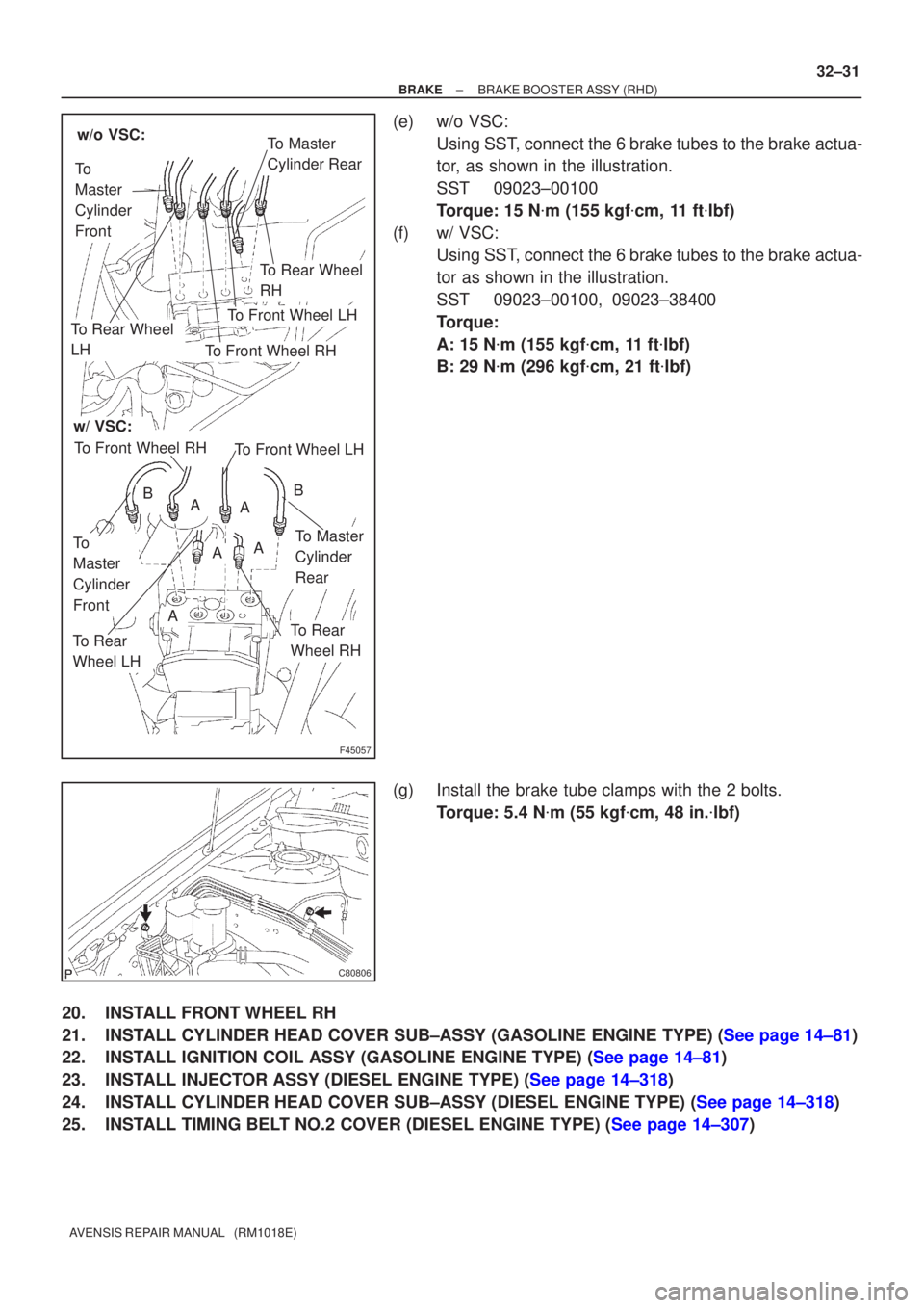
(e) w/o VSC:
Using SST, connect the 6 brake tubes to the brake actua-
tor, as shown in the illustration.
SST 09023±00100
Torque: 15 N �m (155 kgf �cm, 11 ft �lbf)
(f) w/ VSC: Using SST, connect the 6 brake tubes to the brake actua-
tor as shown in the illustration.
SST 09023±00100, 09023±38400
Torque:
A: 15 N �m (155 kgf �cm, 11 ft �lbf)
B: 29 N �m (296 kgf �cm, 21 ft �lbf)
(g) Install the brake tube clamps with the 2 bolts. Torque: 5.4 N �m (55 kgf �cm, 48 in. �lbf)
20. INSTALL FRONT WHEEL RH
21.INSTALL CYLINDER HEAD COVER SUB±ASSY (GASOLINE ENGINE TYPE) (See page 14±81)
22.INSTALL IGNITION COIL ASSY (GASOLINE ENGINE TYPE) (See page 14±81)
23.INSTALL INJECTOR ASSY (DIESEL ENGINE TYPE) (See page 14±318)
24.INSTALL CYLINDER HEAD COVER SUB±ASSY (DIESEL ENGINE TYPE) (See page 14±318)
25.INSTALL TIMING BELT NO.2 COVER (DIESEL ENGINE TYPE) (See page 14±307)
Page 2642 of 5135
32±32
±
BRAKE BRAKE BOOSTER ASSY (RHD)
AVENSIS REPAIR MANUAL (RM1018E)
26. INSTALL ENGINE COVER NO.1
27.INSTALL ENGINE ASSEMBLY WITH TRANSAXLE (1AZ±FSE ENGINE TYPE) (See page 14±204)
28.INSTALL CLUTCH MASTER CYLINDER ASSY (M/T TRANSAXLE) (See page 42±13) SST 09023±00100
29.INSTALL BRAKE MASTER CYLINDER SUB±ASSY (See page 32±13)
(a) w/o VSC: SST 09023±00100
(b) w/ VSC: SST 09023±38400
30.FILL RESERVOIR WITH BRAKE FLUID (See page 32±4)
31.BLEED MASTER CYLINDER (See page 32±4)
(a) w/o VSC: SST 09023±00100, 09023±00100
(b) w/ VSC: SST 09023±00100, 09023±00100
32.BLEED BRAKE LINE (See page 32±4)
33.CHECK AND ADJUST BRAKE PEDAL HEIGHT (See page 32±6)
34.CHECK PEDAL FREE PLAY (See page 32±6)
35.CHECK PEDAL RESERVE DISTANCE (See page 32±6)
36.BLEED CLUTCH PIPE LINE (M/T TRANSAXLE) (See page 42±13)
37.INSPECT AND ADJUST CLUTCH PEDAL SUB±ASSY (M/T TRANSAXLE) (See page 42±2)
38.CHECK FLUID LEVEL IN RESERVOIR (See page 32±4)
39. CHECK BRAKE FLUID LEAKAGE
40. CHECK CLUTCH FLUID LEAKAGE (M/T TRANSAXLE)
Page 2643 of 5135
400DA±02
������������D30339
Neutral
Basic Line
Groove
Neutral
Basic Line
GrooveU241E:
U341E: 40±8
± AUTOMATIC TRANSMISSION / TRANSPARK/NEUTRAL POSITION SWITCH ASSY (ATM)
AVENSIS REPAIR MANUAL (RM1018E)
ADJUSTMENT
1. INSPECT PARK/NEUTRAL POSITION SWITCH ASSY
(a) Apply the parking brake and turn the ignition switch ON.
(b) Depress the brake pedal and check that the engine starts only when the shift lever is set in N or P posi-
tion and it does not start in other position.
(c) Check that the back±up light is on and the reverse warning buzzer sounds only when the shift lever
is set in R position and these do not function in other position.
If a failure is found, check the park/neutral position switch for continuity.
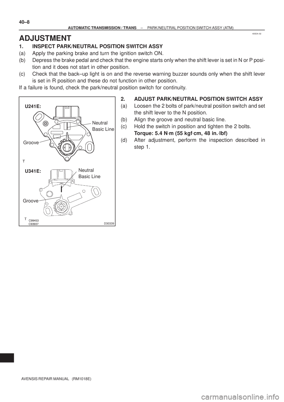
2. ADJUST PARK/NEUTRAL POSITION SWITCH ASSY
(a) Loosen the 2 bolts of park/neutral position switch and set
the shift lever to the N position.
(b) Align the groove and neutral basic line.
(c) Hold the switch in position and tighten the 2 bolts.
Torque: 5.4 N�m (55 kgf�cm, 48 in.�lbf)
(d) After adjustment, perform the inspection described in
step 1.
Page 2649 of 5135
400D7±02
D25120
OK if hot
Add if hot 40±2
± AUTOMATIC TRANSMISSION / TRANSAUTOMATIC TRANSAXLE FLUID (ATM)
AVENSIS REPAIR MANUAL (RM1018E)
AUTOMATIC TRANSAXLE FLUID (ATM)
ON±VEHICLE INSPECTION
1. CHECK THE FLUID LEVEL
HINT:
Drive the vehicle so that the engine and transaxle are at the nor-
mal operating temperature.
Fluid temperature: 70 ± 80 �C (158 ± 176 �F)
(a) Park the vehicle on a level surface and set the parking
brake.
(b) With the engine idling and the brake pedal depressed,
shift the shift lever into all position from P to L position and
return to P position.
(c) Pull out the dipstick and wipe it clean.
(d) Push it back fully into the pipe.
(e) Pull it out and check that the fluid level is in the HOT posi-
tion.
If there are leaks, it is necessary to repair or replace O±rings,
FIPGs, oil seals, plugs or other parts.
Page 2650 of 5135
400D8±02
± AUTOMATIC TRANSMISSION / TRANSAUTOMATIC TRANSAXLE ASSY (ATM)
40±1
AVENSIS REPAIR MANUAL (RM1018E)
AUTOMATIC TRANSAXLE ASSY (ATM)
PRECAUTION
1. The automatic transaxle is composed of highly precision±finished parts which need careful in-
spection before reassembly because even a small nick could cause fluid leakage or affect the
performance. The instructions here are organized in order to work on only one component
group at a time. This will help avoid confusion comes from the similar±looking part of the differ-
ent sub±assemblies being on your workbench at the same time. Inspect and repair the compo-
nent groups from the converter housing side. Complete the inspection, repair and reassembly
before proceeding to the next component group. If a defect is found in a certain component
group during reassembly, inspect and repair this group immediately. If a component group can-
not be assembled because the necessary parts are being ordered, be sure to keep all the parts
of the group in a separate container while proceeding with disassembly, inspection, repair and
reassembly of the other component groups.
Recommended ATF: T±IV
2. All the disassembled parts should be washed clean and any fluid passages and holes should
be blown through with compressed air.
3. Dry all parts with compressed air. Never use shop rags to dry them.
4. Be careful of ATF or kerosene not to be squirted over your face when using compressed air.
5. The recommended automatic transaxle fluid or kerosene should be used for cleaning.
6. After cleaning, the parts should be arranged in the correct order for efficient inspection, repairs,
and reassembly.
7. When disassembling the valve body, be sure to match each valve together with the correspond-
ing spring.
8. New discs for the replacement of the brakes and clutches must be soaked in ATF for at least
15 minutes before reassembly.
9. All the oil seal rings, clutch discs, clutch plates, rotating parts, and sliding surfaces should be
coated with ATF prior to reassembly.
10. Replace all the gaskets and rubber O±rings.
11. Do not apply adhesive cements to the gaskets and similar parts.
12. Make sure that the ends of the snap ring are not aligned with one of the cutouts and are installed
in the groove correctly.
13. If a worn bushing is to be replaced, the sub±assembly containing the bushing must also be re-
placed.
14. Check the thrust bearings and races for wear or damage. Replace them as necessary.
15. Use petroleum jelly to keep the parts in place.
16. When working with FIPG material, you must follow the procedure below.
�Remove all the old packing (FIPG) material from the gasket surface using a razor blade and a
gasket scraper.
�Thoroughly clean all the components to remove all the loose material.
�Clean both the sealing surfaces with non±residue solvent.
�Parts must be reassembled within 10 minutes of application. Otherwise, the packing (FIPG) ma-
terial must be removed and reapplied.
Page 2651 of 5135
330C8±01
F45710
Contract
F06409
G22379
������G22380
33±14
±
PARKING BRAKE PARKING BRAKE ASSY
AVENSIS REPAIR MANUAL (RM1018E)
OVERHAUL
HINT:
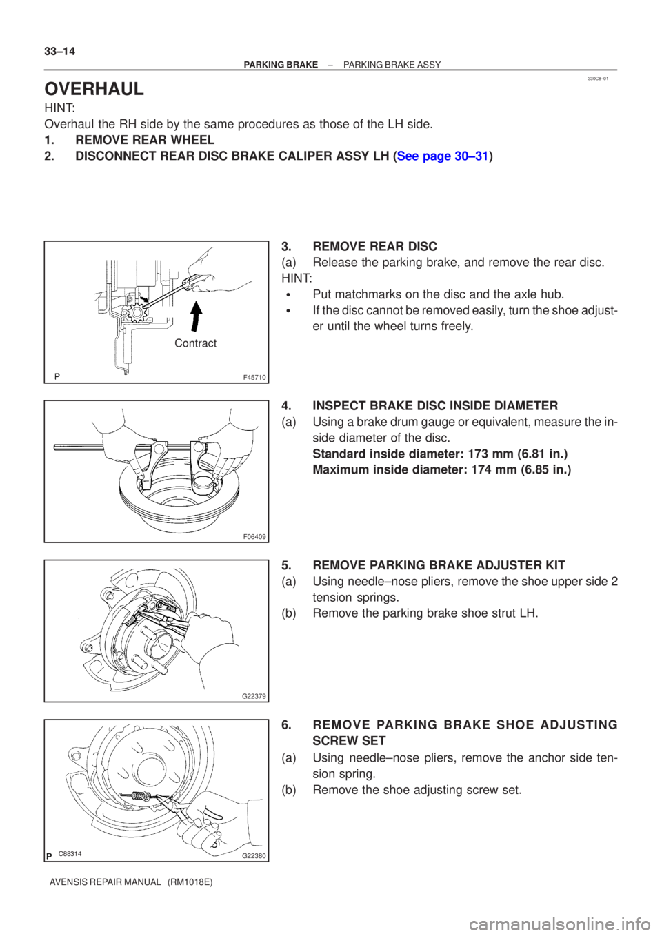
Overhaul the RH side by the same procedures as those of the LH side.
1. REMOVE REAR WHEEL
2.DISCONNECT REAR DISC BRAKE CALIPER ASSY LH (See page 30±31) 3. REMOVE REAR DISC
(a) Release the parking brake, and remove the rear disc.
HINT:
�Put matchmarks on the disc and the axle hub.
�If the disc cannot be removed easily, turn the shoe adjust-
er until the wheel turns freely.
4. INSPECT BRAKE DISC INSIDE DIAMETER
(a) Using a brake drum gauge or equivalent, measure the in- side diameter of the disc.
Standard inside diameter: 173 mm (6.81 in.)
Maximum inside diameter: 174 mm (6.85 in.)
5. REMOVE PARKING BRAKE ADJUSTER KIT
(a) Using needle±nose pliers, remove the shoe upper side 2 tension springs.
(b) Remove the parking brake shoe strut LH.
6. REMOVE PARKING BRAKE SHOE ADJUSTING
SCREW SET
(a) Using needle±nose pliers, remove the anchor side ten- sion spring.
(b) Remove the shoe adjusting screw set.