Page 3905 of 5135
A62378
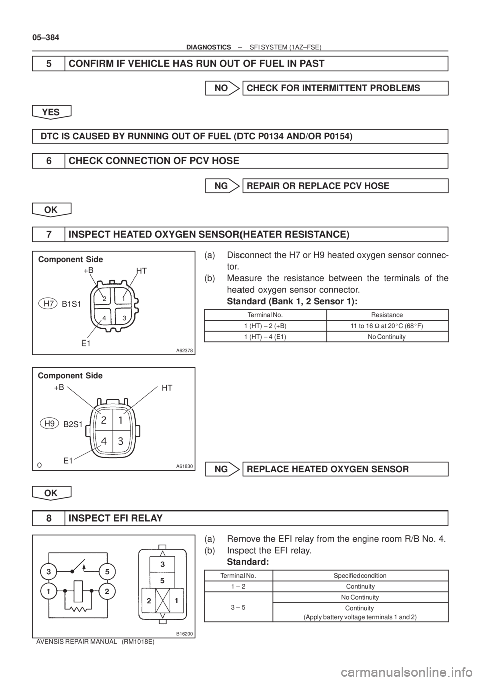
Component Side
+B
HT
E1
� �
� �B1S1 H7
A61830
+B
HT
E1 Component Side
B2S1 H9
B16200
05±384
± DIAGNOSTICSSFI SYSTEM (1AZ±FSE)
AVENSIS REPAIR MANUAL (RM1018E)
5 CONFIRM IF VEHICLE HAS RUN OUT OF FUEL IN PAST
NO CHECK FOR INTERMITTENT PROBLEMS
YES
DTC IS CAUSED BY RUNNING OUT OF FUEL (DTC P0134 AND/OR P0154)
6 CHECK CONNECTION OF PCV HOSE
NG REPAIR OR REPLACE PCV HOSE
OK
7 INSPECT HEATED OXYGEN SENSOR(HEATER RESISTANCE)
(a) Disconnect the H7 or H9 heated oxygen sensor connec-
tor.
(b) Measure the resistance between the terminals of the
heated oxygen sensor connector.
Standard (Bank 1, 2 Sensor 1):
Terminal No.Resistance
1 (HT) ± 2 (+B)11 to 16 � at 20�C (68�F)
1 (HT) ± 4 (E1)No Continuity
NG REPLACE HEATED OXYGEN SENSOR
OK
8 INSPECT EFI RELAY
(a) Remove the EFI relay from the engine room R/B No. 4.
(b) Inspect the EFI relay.
Standard:
Terminal No.Specified condition
1 ± 2Continuity
No Continuity
3 ± 5Continuity
(Apply battery voltage terminals 1 and 2)
Page 3906 of 5135

Heated Oxy")
A76821
Wire Harness Side
B1S1B2S1 H7 H9
Heated Oxygen Sensor Connector OX
HT
OX
HT
E1E1
A76823
OX2A
ECM Connector E12
OX1A
HT2A HT1A
E2 E13
A72920
Reference (Bank 1 Sensor 1 System Drawing)
Heated Oxygen Sensor
EFI Relay
Heater
Sensor
OX1A HT1A
Duty
Control ECM
From
Battery
EFI Fuse
E2 EFI No. 2
Fuse
MREL OX HT
E1 +B
± DIAGNOSTICSSFI SYSTEM (1AZ±FSE)
05±385
AVENSIS REPAIR MANUAL (RM1018E)
NG REPLACE EFI RELAY
OK
9 CHECK HARNESS AND CONNECTOR(HEATED OXYGEN SENSOR ± ECM)
(a) Disconnect the H7 or H9 heated oxygen sensor connec-
tor.
(b) Disconnect the E12 and E13 ECM connectors.
(c) Check for continuity between the wire harness side con-
nectors.
Standard (Check for open):
Symbols (Terminal No.)Specified condition
OX (H7±3) ± OX1A (E12±22)
HT (H7±1) ± HT1A (E12±5)
E1 (H7±4) ± E2 (E13±28)ContinuityOX (H8±3) ± OX2A (E12±23)Continuity
HT (H8±1) ± HT2A (E12±4)
E1 (H8±4) ± E2 (E13±28)
Standard (Check for short):
Symbols (Terminal No.)Specified condition
OX (H7±3) or OX1A (E12±22) ± Body ground
HT (H7±1) or HT1A (E12±5) ± Body groundNo continuityOX (H8±3) or OX2A (E12±23) ± Body groundNo continuity
HT (H8±1) or HT2A (E12±4) ± Body ground
HINT:
�The OX1A and HT1A means the heated oxygen sensor
bank 1 sensor 1.
�The OX2A and HT2A means the heated oxygen sensor
bank 2 sensor 1.
NG REPAIR OR REPLACE HARNESS OR
CONNECTOR
OK
Page 3907 of 5135
05±386
±
DIAGNOSTICS SFI SYSTEM(1AZ±FSE)
AVENSIS REPAIR MANUAL (RM1018E)
10CHECK WHETHER MISFIRE IS OCCURRED OR NOT BY MONITORING DTC AND DATA LIST
NGPERFORM TROUBLESHOOTING FOR MISFIRE
(See page 05±294)
OK
11CHECK AIR INDUCTION SYSTEM
(a)Check for vacuum leaks in the air induction system. NGREPAIR OR REPLACE AIR INDUCTION SYSTEM
OK
12CHECK FUEL PRESSURE(LOW PRESSURE) (See page 11±33)
NG CHECK AND REPLACE FUEL PUMP, PRESSURE REGULATOR, FUEL PIPE LINE AND
FILTER
OK
13CHECK FUEL PRESSURE(HIGH PRESSURE) (See page 11±33)
NG CHECK AND REPLACE FUEL PUMP, FUEL PRESSURE SENSOR, WIRING AND FUEL
LEAKAGE
OK
14 CHECK FOR EXHAUST GAS LEAK
NG REPAIR OR REPLACE EXHAUST GAS LEAKAGE POINT
OK
Page 3908 of 5135
±
DIAGNOSTICS SFI SYSTEM (1AZ±FSE)
05±387
AVENSIS REPAIR MANUAL (RM1018E)
15 CONFIRM IF ANY MISFIRING DTCS WERE PRESENT AT STEP 1
(a) Misfiring DTC ºP0301, P0302, P0303 and/or P0304º was present at step 1.
NO REPLACE HEATED OXYGEN SENSOR
YES
16REPLACE FUEL INJECTOR ASSY (See page 11±42)
HINT:
If one or more the misfiring DTCs ºP0301, P0302, P0303 and/or P0304º\
were present at step 1, replace the
injector(s) mounted on the misfiring cylinder(s) that is referred by the DTC(s)\
with normal injector(s). GO
17PERFORM CONFIRMATION DRIVING PATTERN (See page 05±363)
HINT:
Clear all DTCs prior to performing the confirmation driving pattern.GO
18 READ OUTPUT DTC(DTC P0134 AND/OR P0154 ARE OUTPUT AGAIN)
(a) Read the DTC using the hand±held tester. Result:
Display (DTC output)Proceed to
ºP0134 and/or P0154º are not output againA
ºP0134 and/or P0154º are output againB
B REPLACE FUEL INJECTOR ASSY
A
REPLACE HEATED OXYGEN SENSOR
Page 3909 of 5135

AVENSIS REPAIR MANUAL (RM1018E)
DTCP0136OXYGEN SENSOR CIRCUIT MALFUNCTION (BANK 1 SENSOR 2)
DTCP0156OXYGEN SENSOR CIRCUIT MALFUNCTION (BANK 2 SENSOR 2)
CI")
05±388
±
DIAGNOSTICS SFI SYSTEM(1AZ±FSE)
AVENSIS REPAIR MANUAL (RM1018E)
DTCP0136OXYGEN SENSOR CIRCUIT MALFUNCTION (BANK 1 SENSOR 2)
DTCP0156OXYGEN SENSOR CIRCUIT MALFUNCTION (BANK 2 SENSOR 2)
CIRCUIT DESCRIPTION
Refer to DTC P0130 on page 05±363.
DTC NoDTC Detection ConditionTrouble Area
P0136
P0156
If the following two conditions are satisfied at a time
(2 trip detection logic):
(a) The ECM records cycles which the vehicle driving and
stops 8 times or more.
(b) There was no change in the rich and lean outputs from heated oxygen sensor (sensor 2) for the 360 seconds un-
der air fuel ratio feedback control. (Throttle was not closed)
�Open or short in heated oxygen sensor (bank 1, 2 sensor 2)
circuit
� Heated oxygen sensor (bank 1, 2 sensor 2)
� Heated oxygen sensor heater (bank 1, 2 sensor 2)
� EFI relay
HINT:
�Bank 1 refers to the No. 1 and No. 4 cylinders.
�Bank 2 refers to the No. 2 and No. 3 cylinders.
�Sensor 2 refers to the sensor farthest away from the engine assembly.
WIRING DIAGRAM
Refer to DTC P0130 on page 05±363.
05CKC±01
Page 3910 of 5135

IG SW OFF Once
40 sec.
or more
60 sec.
or more 10 sec.Twice
40 sec.
or more
(f)
12 times
40 sec.
or more
10 sec.10 sec.
(a), (b) (d)
(e)
Idling (c) (d)
(e) (d)
(e")
A58686
Vehicle speed40 km/h
(25 mph)
IG SW OFF Once
40 sec.
or more
60 sec.
or more 10 sec.Twice
40 sec.
or more
(f)
12 times
40 sec.
or more
10 sec.10 sec.
(a), (b) (d)
(e)
Idling (c) (d)
(e) (d)
(e)
±
DIAGNOSTICS SFI SYSTEM(1AZ±FSE)
05±389
AVENSIS REPAIR MANUAL (RM1018E)
CONFIRMATION DRIVING PATTERN
(a)Connect the hand±held tester to the DLC3.
(b)Switch the hand±held tester from the normal mode to the check (test)\
mode (See page 05±294).
(c) Start the engine and let the engine idle for 60 seconds or more.
(d) Drive the vehicle at 40 km/h (25 mph) or more for 40 seconds or more.
(e) Let the engine idle for 10 seconds or more.
(f) Perform steps (d) and (e) 12 times.
HINT:
If a malfunction exists, the CHK ENG will be illuminated on the multi in\
formation display during step (f).
NOTICE:
If the conditions in this test are not strictly followed, detection of a malfunction will not occur. If you
do not have a hand±held tester, turn the ignition switch OFF after performing steps from (c) to (f), then
perform steps from (c) to (f) again.
INSPECTION PROCEDURE
HINT:
Hand±held tester only:
Narrowing down the trouble area is possible by performing the ºA/F CONTROLº ACTIVE TEST (heated oxy-
gen sensor or other trouble areas can be distinguished).
(a) Perform ACTIVE TEST using the hand±held tester (A/F CONTROL).
HINT:
ºA/F CONTROLº is an ACTIVE TEST which changes the injection volume\
±12.5 % or +25 %.
(1) Connect the hand±held tester to the DLC3 on the vehicle.
(2) Turn the ignition switch ON.
(3) Warm up the engine by running the engine at 2,500 rpm for approximately 9\
0 sec.
(4) Select the item ºDIAGNOSIS / OBD/MOBD / ACTIVE TEST / A/F CONTROLº\
.
(5) Perform ºA/F CONTROLº with the engine in an idle condition (press\
the right or left button).
Result:
Heated oxygen sensor reacts in accordance with increase and decrease of injection volume:
+25 % � rich output: More than 0.55 V
±12.5 % � lean output: Less than 0.4 V
Page 3911 of 5135

Injection volume
Output voltage
Output voltage of heated oxy")
+25 %
±12.5 %
More than 0.55 V
Less than 0.4V
Case 1
Case 2
Case 3
Case 4
Output voltage of heated oxygen
sensor (sensor 1: front sensor)
Injection volume
Output voltage
Output voltage of heated oxygen
sensor (sensor 2: rear sensor)Mainly suspect
trouble area
OK
+25 %
±12.5 %
More than 0.55 V
Less than 0.4V
Injection volume
Output voltage
+25 %
±12.5 %
More than 0.55 V
Less than 0.4V
Injection volume
Output voltage
Sensor 1: front sensor
(sensor 1, heater, sensor 1
circuit)
+25 %
±12.5 %
More than 0.55 V
Less than 0.4V
Injection volume
Output voltage
+25 %
±12.5 %
Injection volume
Output voltage
NG
+25 %
±12.5 %
Injection volume
Output voltage
NG
+25 %
±12.5 %
Injection volume
Output voltage
NG
+25 %
±12.5 %
Injection volume
Output voltage
NGExtremely rich or lean actual
air±fuel ratio
(Injector, fuel pressure, gas
leakage in exhaust system,
etc.) OK
OK
OK
No reaction
No reaction
No reaction No reaction
�
Sensor 2: rear sensor
(sensor 2, heater, sensor 2
circuit) 05±390
± DIAGNOSTICSSFI SYSTEM (1AZ±FSE)
AVENSIS REPAIR MANUAL (RM1018E)
NOTICE:
There is a few seconds delay in the sensor 1 (front sensor) output. And there is about 20 seconds
delay in the sensor 2 (rear sensor).
The following A/F CONTROL procedure enables the technician to check and graph the voltage outputs of
both the heated oxygen sensors.
For displaying the graph indication, enter ºACTIVE TEST / A/F CONTROL / USER DATAº, then select ºO2S
B1S1 and O2S B1S2º or ºO2S B2S1 and O2S B2S2º by pressing ºYESº button and push ºENTERº button
before pressing ºF4º button.
HINT:
�If different DTCs related to different systems that have terminal E2 as the ground terminal are output
simultaneously, terminal E2 may be open.
�Read freeze frame data using the hand±held tester. Freeze frame data records the engine conditions
when a malfunction is detected. When troubleshooting, it is useful for determining whether the vehicle
was running or stopped, the engine was warmed up or not, the air±fuel ratio was lean or rich, etc. at
the time of the malfunction.
Page 3912 of 5135

05±391
AVENSIS REPAIR MANUAL (RM1018E)
1CHECK OTHER DTC OUTPUT(IN ADDITION TO DTC P0136 AND/OR P0156)
(a)R")
A62378
+BHT
E1
�
�
�
�
Component Side
B2S2
H10
B1S2
H8
±
DIAGNOSTICS SFI SYSTEM(1AZ±FSE)
05±391
AVENSIS REPAIR MANUAL (RM1018E)
1CHECK OTHER DTC OUTPUT(IN ADDITION TO DTC P0136 AND/OR P0156)
(a)Read the DTC using the hand±held tester.
Result:
Display (DTC output)Proceed to
Only ºP0136 and/or P0156º are outputA
ºP0136 or P0156º and other DTCs are outputB
HINT:
If any other codes besides ºP0136 and/or P0156º are output, perform \
the troubleshooting for those DTCs
first.
BGO TO RELEVANT DTC CHART(See page 05±309)
A
2 READ VALUE OF HAND±HELD TESTER(OUTPUT VOLTAGE OF HEATED OXYGEN SENSOR)
(a) After warming up the engine, run the engine at 2,500 rpm for 3 minutes.
(b) Read the output voltage of the heated oxygen sensor (sensor 2) when the engine rpm is suddenly\
in-
creased.
HINT:
Quickly accelerate the engine to 4,000 rpm 3 times by using the accelerator ped\
al. The output voltage of heated oxygen sensor (sensor 2): Alternates from\
0.4 V or less to 0.5 V
or more.
OK Go to step 6
NG
3 INSPECT HEATED OXYGEN SENSOR(HEATER RESISTANCE)
(a) Disconnect the H8 or H10 heated oxygen sensor connec- tor.
(b) Measure the resistance between the terminals of the
heated oxygen sensor connector.
Standard (Bank 1, 2 Sensor 2):
Terminal No.Resistance
1 (HT) ± 2 (+B)11 to 16 � at 20 �C (68 �F)
1 (HT) ± 4 (E1)No Continuity
NG REPLACE HEATED OXYGEN SENSOR
OK

AVENSIS REPAIR MANUAL (RM1018E)
10CHECK WHETHER MISFIRE IS OCCURRED OR NOT BY MONITORING DTC AND DATA LIST
NGPERFORM TROUBLESHOOTING FOR MISFIRE
(See page")

05±387
AVENSIS REPAIR MANUAL (RM1018E)
15 CONFIRM IF ANY MISFIRING DTCS WERE PRESENT AT STEP 1
(a) Misfiring DTC ºP0301, P0302, P0303 and/or P0304º was presen")