Page 3279 of 5135
720J7±01
B70318
Front Seat Headrest Assy
Vertical Seat Adjuster KnobReclining Adjuster
Release Handle LH Front Seat Cushion Shield LH Front Seat Inner
Belt Assy LH
Front Seat Cushion Shield Inner LHSeparate Type
Front Seatback Cover (w/ Seat Heater)Separate Type Front Seatback
Spring Assy (w/ Side Airbag)
Separate Type
Front Seat Cushion Cover
(w/ Seat Heater) Separate Type
Front Seat Cushion PadSeparate Type Front Seatback Pad
N�m (kgf�cm, ft�lbf) : Specified torque
� Non±reusable partFront Seat
Headrest Support Assy
� Hog Ring � Hog Ring
37 (375, 27)
37 (375, 27)
42 (420, 31)
Front Seat Adjuster LHSeat Track Bracket Cover Inner LHFront Seat Reclining
Housing Sub±assy LH
Reclining Control Lever LH Reclining Adjuster Knob Cap LH
Vertical Seat Adjuster Knob Cap
25 (255, 18)
37 (375, 27)
25 (255, 18)
8.0 (82, 71 in.�lbf)
Seat Track Outer Cover LH
Seat Position Airbag Sensor
Seat Heater Control Sub±assy
Seat Heater Control Wire Harness
± SEATFRONT SEAT ASSEMBLY LH (MANUAL SEAT TYPE)
72±15
AVENSIS REPAIR MANUAL (RM1018E)
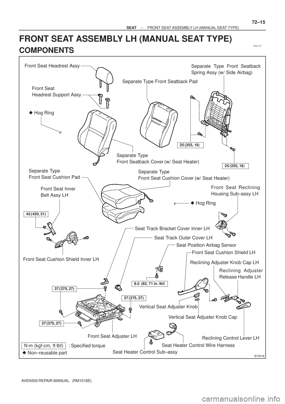
FRONT SEAT ASSEMBLY LH (MANUAL SEAT TYPE)
COMPONENTS
Page 3281 of 5135
B70317
Claw
Clip
B60977
72±12
± SEATFRONT SEAT ASSEMBLY LH (POWER SEAT TYPE)
AVENSIS REPAIR MANUAL (RM1018E)
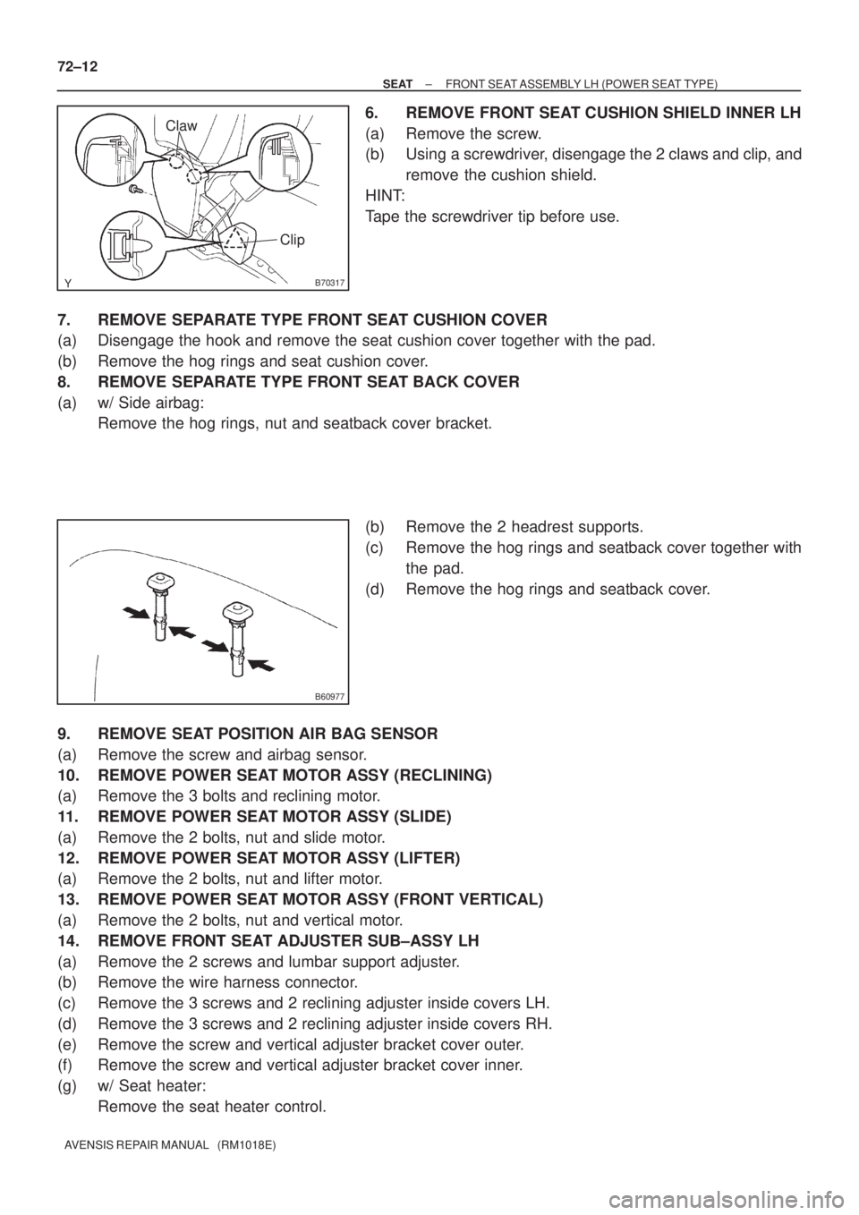
6. REMOVE FRONT SEAT CUSHION SHIELD INNER LH
(a) Remove the screw.
(b) Using a screwdriver, disengage the 2 claws and clip, and
remove the cushion shield.
HINT:
Tape the screwdriver tip before use.
7. REMOVE SEPARATE TYPE FRONT SEAT CUSHION COVER
(a) Disengage the hook and remove the seat cushion cover together with the pad.
(b) Remove the hog rings and seat cushion cover.
8. REMOVE SEPARATE TYPE FRONT SEAT BACK COVER
(a) w/ Side airbag:
Remove the hog rings, nut and seatback cover bracket.
(b) Remove the 2 headrest supports.
(c) Remove the hog rings and seatback cover together with
the pad.
(d) Remove the hog rings and seatback cover.
9. REMOVE SEAT POSITION AIR BAG SENSOR
(a) Remove the screw and airbag sensor.
10. REMOVE POWER SEAT MOTOR ASSY (RECLINING)
(a) Remove the 3 bolts and reclining motor.
11. REMOVE POWER SEAT MOTOR ASSY (SLIDE)
(a) Remove the 2 bolts, nut and slide motor.
12. REMOVE POWER SEAT MOTOR ASSY (LIFTER)
(a) Remove the 2 bolts, nut and lifter motor.
13. REMOVE POWER SEAT MOTOR ASSY (FRONT VERTICAL)
(a) Remove the 2 bolts, nut and vertical motor.
14. REMOVE FRONT SEAT ADJUSTER SUB±ASSY LH
(a) Remove the 2 screws and lumbar support adjuster.
(b) Remove the wire harness connector.
(c) Remove the 3 screws and 2 reclining adjuster inside covers LH.
(d) Remove the 3 screws and 2 reclining adjuster inside covers RH.
(e) Remove the screw and vertical adjuster bracket cover outer.
(f) Remove the screw and vertical adjuster bracket cover inner.
(g) w/ Seat heater:
Remove the seat heater control.
Page 3282 of 5135
B50126
Hog Ring Pliers
B65860
± SEATFRONT SEAT ASSEMBLY LH (POWER SEAT TYPE)
72±13
AVENSIS REPAIR MANUAL (RM1018E)
15. INSTALL POWER SEAT MOTOR ASSY (RECLINING)
(a) Install the reclining motor with the 3 bolts.
Torque: 4.5 N�m (46 kgf�cm, 40 in.�lbf)
16. INSTALL POWER SEAT MOTOR ASSY (SLIDE)
(a) Install the slide motor with the 2 bolts and nut.
Torque:
Bolt 4.0 N�m (41 kgf�cm, 35 in.�lbf)
Nut 3.5 N�m (36 kgf�cm, 31 in.�lbf)
17. INSTALL POWER SEAT MOTOR ASSY (LIFTER)
(a) Install the lifter motor with the 2 bolts and nut.
Torque:
Bolt 2.5 N�m (25 kgf�cm, 22 in.�lbf)
Nut 25 N�m (255 kgf�cm, 18 ft�lbf)
18. INSTALL POWER SEAT MOTOR ASSY (FRONT VERTICAL)
(a) Install the vertical motor with the 2 bolts and nut.
Torque:
Bolt 2.5 N�m (25 kgf�cm, 22 in.�lbf)
Nut 25 N�m (255 kgf�cm, 18 ft�lbf)
19. INSTALL SEAT POSITION AIR BAG SENSOR
(a) Install the airbag sensor with the screw.
Torque: 8.0 N�m (82 kgf�cm, 71 in.�lbf)
20. INSTALL SEPARATE TYPE FRONT SEAT BACK COVER
(a) Install the lumbar support adjuster with the 2 screws.
(b) Install the seatback pad.
(c) Cover the top of the seatback pad with the seatback cover.
(d) Install the 2 headrest supports.
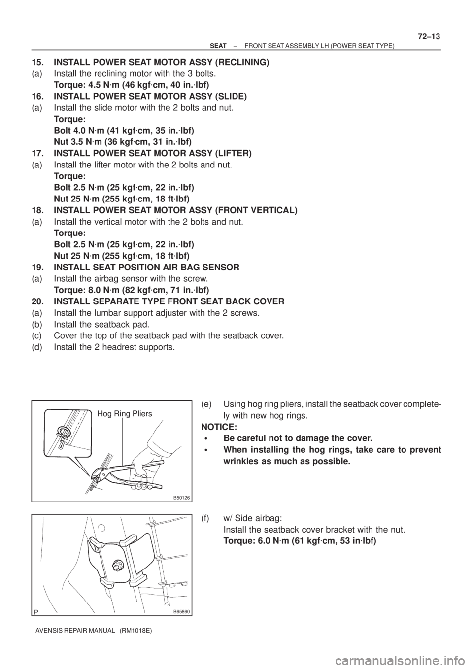
(e) Using hog ring pliers, install the seatback cover complete-
ly with new hog rings.
NOTICE:
�Be careful not to damage the cover.
�When installing the hog rings, take care to prevent
wrinkles as much as possible.
(f) w/ Side airbag:
Install the seatback cover bracket with the nut.
Torque: 6.0 N�m (61 kgf�cm, 53 in�lbf)
Page 3284 of 5135
720J5±01
B70315
Headrest Support
Power Seat Switch Assy
Power Seat Switch Knob Front Seat Inner Belt Assy LH
Front Seat Headrest Assy
� Hog Ring
Separate Type Front Seatback Cover
� Hog Ring
Front Seatback Pad
Seat Cushion Pad
Reclining Adjuster Inside Cover RH
Reclining Adjuster Inside Cover LH
Vertical Adjuster Bracket Cover Outer
Wire Harness Connector
Front Seat Cushion Shield LHHeadrest Support
Lumbar Support Adjuster Assy
Seat Track Cover
42 (428, 31)
6.0 (61, 53 in.�lbf)
: Specified torqueN�m (kgf�cm, ft�lbf)
� Non±reusable part
Front Power Seat Switch
37 (375, 27) Clip
Clip
8.0 (82, 71 in.�lbf)
Seat Position Airbag Sensor
Bush
37 (375, 27)37 (375, 27)
Front Seat Cushion Shield Front Seat Cushion Shield Inner LH
4.5 (46, 40 in.�lbf)
4.0 (41, 35 in.�lbf)
2.5 (25, 22 in.�lbf)
2.5 (25, 22 in.�lbf)
25 (255, 18)
3.5 (36, 31 in.�lbf)
25 (255, 18) Power Seat Motor Assy (Lifter)
(Front Vertical)Power Seat Motor Assy
(Reclining)Power Seat Motor Assy
Power Seat Motor AssyFront Seat Adjuster Assy LH Separate Type Front Seat Cushion Cover Separate Type Front
Vertical Adjuster
Inner No.1 LH
(w/ Seat Heater)
(w/ Seat Heater)
Seat Heater Control Sub±assy
Bracket Cover Inner
(Slide)
72±10
± SEATFRONT SEAT ASSEMBLY LH (POWER SEAT TYPE)
AVENSIS REPAIR MANUAL (RM1018E)
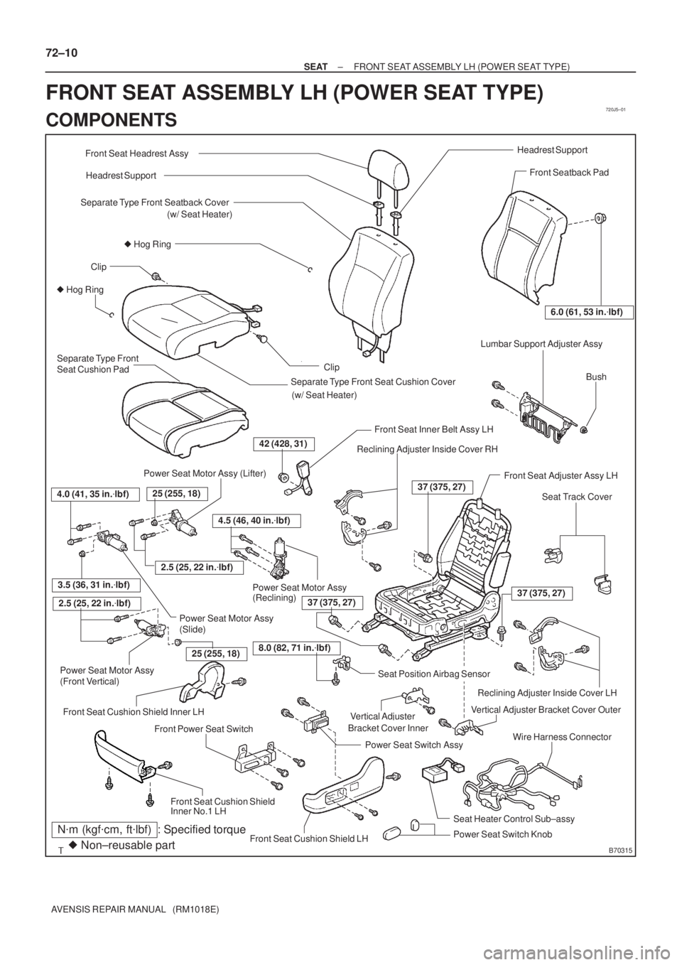
FRONT SEAT ASSEMBLY LH (POWER SEAT TYPE)
COMPONENTS
Page 3303 of 5135
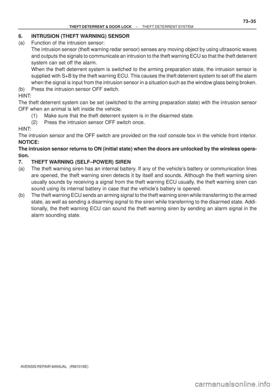
± THEFT DETERRENT & DOOR LOCKTHEFT DETERRENT SYSTEM
73±35
AVENSIS REPAIR MANUAL (RM1018E)
6. INTRUSION (THEFT WARNING) SENSOR
(a) Function of the intrusion sensor:
The intrusion sensor (theft warning redar sensor) senses any moving object by using ultrasonic waves
and outputs the signals to communicate an intrusion to the theft warning ECU so that the theft deterrent
system can set off the alarm.
When the theft deterrent system is switched to the arming preparation state, the intrusion sensor is
supplied with S+B by the theft warning ECU. This causes the theft deterrent system to set off the alarm
when the signal is input from the intrusion sensor in a situation such as the window glass being broken.
(b) Press the intrusion sensor OFF switch.
HINT:
The theft deterrent system can be set (switched to the arming preparation state) with the intrusion sensor
OFF when an animal is left inside the vehicle.
(1) Make sure that the theft deterrent system is in the disarmed state.
(2) Press the intrusion sensor OFF switch once.
HINT:
The intrusion sensor and the OFF switch are provided on the roof console box in the vehicle front interior.
NOTICE:
The intrusion sensor returns to ON (initial state) when the doors are unlocked by the wireless opera-
tion.
7. THEFT WARNING (SELF±POWER) SIREN
(a) The theft warning siren has an internal battery. If any of the vehicle's battery or communication lines
are opened, the theft warning siren detects it by itself and sounds. Although the theft warning siren
usually sounds by receiving a signal from the theft warning ECU usually, the theft warning siren can
sound using its internal battery in case that the vehicle's battery is opened.
(b) The theft warning ECU sends an arming signal to the theft warning siren while transferring to the armed
state, as well as sending a disarming signal to the siren while transferring to the disarmed state. Addi-
tionally, the theft warning ECU can sound the theft warning siren by sending an alarm signal in the
alarm sounding state.
Page 3460 of 5135
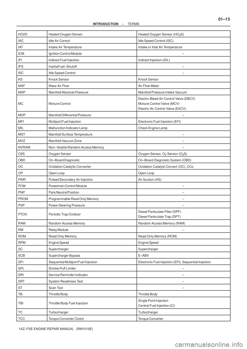
± INTRODUCTIONTERMS
01±13
1AZ±FSE ENGINE REPAIR MANUAL (RM1019E) HO2S
Heated Oxygen SensorHeated Oxygen Sensor (HO2S)
IACIdle Air ControlIdle Speed Control (ISC)
IATIntake Air TemperatureIntake or Inlet Air Temperature
ICMIgnition Control Module±
IFIIndirect Fuel InjectionIndirect Injection (IDL)
IFSInertia Fuel±Shutoff±
ISCIdle Speed Control±
KSKnock SensorKnock Sensor
MAFMass Air FlowAir Flow Meter
MAPManifold Absolute PressureManifold Pressure Intake Vacuum
MCMixture Control
Electric Bleed Air Control Valve (EBCV)
Mixture Control Valve (MCV)
Electric Air Control Valve (EACV)
MDPManifold Differential Pressure±
MFIMultiport Fuel InjectionElectronic Fuel Injection (EFI)
MILMalfunction Indicator LampCheck Engine Lamp
MSTManifold Surface Temperature±
MVZManifold Vacuum Zone±
NVRAMNon±Volatile Random Access Memory±
O2SOxygen SensorOxygen Sensor, O2 Sensor (O2S)
OBDOn±Board DiagnosticOn±Board Diagnostic System (OBD)
OCOxidation Catalytic ConverterOxidation Catalyst Convert (OC), CCo
OPOpen LoopOpen Loop
PAIRPulsed Secondary Air InjectionAir Suction (AS)
PCMPowertrain Control Module±
PNPPark/Neutral Position±
PROMProgrammable Read Only Memory±
PSPPower Steering Pressure±
PTOXPeriodic Trap OxidizerDiesel Particulate Filter (DPF)
Diesel Particulate Trap (DPT)
RAMRandom Access MemoryRandom Access Memory (RAM)
RMRelay Module±
ROMRead Only MemoryRead Only Memory (ROM)
RPMEngine SpeedEngine Speed
SCSuperchargerSupercharger
SCBSupercharger BypassE±ABV
SFISequential Multiport Fuel InjectionElectronic Fuel Injection (EFI), Sequential Injection
SPLSmoke Puff Limiter±
SRIService Reminder Indicator±
SRTSystem Readiness Test±
STScan Tool±
TBThrottle BodyThrottle Body
TBIThrottle Body Fuel InjectionSingle Point Injection
Central Fuel Injection (Ci)
TCTurbochargerTurbocharger
TCCTorque Converter ClutchTorque Converter
Page 3461 of 5135
01±14
± INTRODUCTIONTERMS
1AZ±FSE ENGINE REPAIR MANUAL (RM1019E) TCM
Transmission Control ModuleTransmission ECU, ECT ECU
TPThrottle PositionThrottle Position
TRTransmission Range±
TVVThermal Vacuum ValveBimetallic Vacuum Switching Valve (BVSV)
Thermostatic Vacuum Switching Valve (TVSV)
TWCThree±Way Catalytic Converter
Three±Way Catalytic (TWC)
Manifold Converter
CC
RO
TWC+OCThree±Way + Oxidation Catalytic ConverterCCR + CCo
VA FVolume Air FlowAir Flow Meter
VRVoltage RegulatorVoltage Regulator
VSSVehicle Speed SensorVehicle Speed Sensor
WOTWide Open ThrottleFull Throttle
WU±OCWarm Up Oxidation Catalytic Converter±
WU±TWCWarm Up Three±Way Catalytic Converter±
3GRThird Gear±
4GRFourth Gear±
Page 3462 of 5135
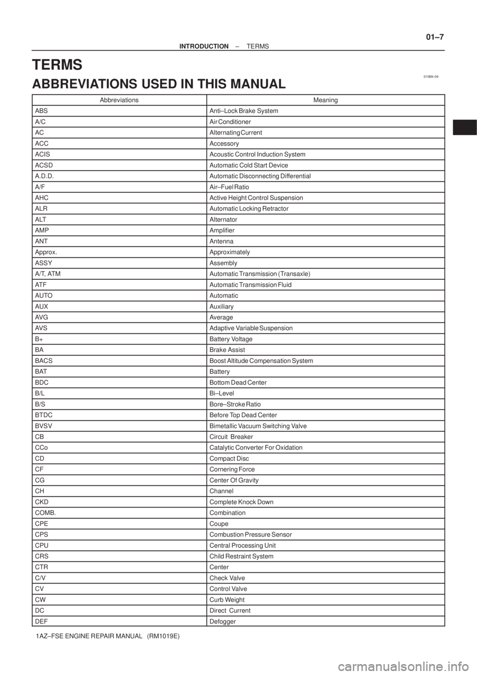
010B9±09
± INTRODUCTIONTERMS
01±7
1AZ±FSE ENGINE REPAIR MANUAL (RM1019E)
TERMS
ABBREVIATIONS USED IN THIS MANUAL
AbbreviationsMeaning
ABSAnti±Lock Brake System
A/CAir Conditioner
ACAlternating Current
ACCAccessory
ACISAcoustic Control Induction System
ACSDAutomatic Cold Start Device
A.D.D.Automatic Disconnecting Differential
A/FAir±Fuel Ratio
AHCActive Height Control Suspension
ALRAutomatic Locking Retractor
ALTAlternator
AMPAmplifier
ANTAntenna
Approx.Approximately
ASSYAssembly
A/T, ATMAutomatic Transmission (Transaxle)
AT FAutomatic Transmission Fluid
AUTOAutomatic
AUXAuxiliary
AV GAverage
AV SAdaptive Variable Suspension
B+Battery Voltage
BABrake Assist
BACSBoost Altitude Compensation System
BATBattery
BDCBottom Dead Center
B/LBi±Level
B/SBore±Stroke Ratio
BTDCBefore Top Dead Center
BVSVBimetallic Vacuum Switching Valve
CBCircuit Breaker
CCoCatalytic Converter For Oxidation
CDCompact Disc
CFCornering Force
CGCenter Of Gravity
CHChannel
CKDComplete Knock Down
COMB.Combination
CPECoupe
CPSCombustion Pressure Sensor
CPUCentral Processing Unit
CRSChild Restraint System
CTRCenter
C/VCheck Valve
CVControl Valve
CWCurb Weight
DCDirect Current
DEFDefogger