Page 3017 of 5135
600A0±04
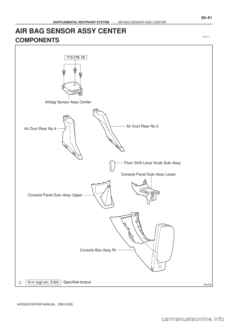
H42700N�m (kgf�cm, ft�lbf): Specified torque
Floor Shift Lever Knob Sub±Assy
Console Panel Sub±Assy Upper
Console Panel Sub±Assy Lower
Console Box Assy Rr
Air Duct Rear No.3Air Duct Rear No.4Airbag Sensor Assy Center
17.5 (178, 13)
± SUPPLEMENTAL RESTRAINT SYSTEMAIR BAG SENSOR ASSY CENTER
60±61
AVENSIS REPAIR MANUAL (RM1018E)
AIR BAG SENSOR ASSY CENTER
COMPONENTS
Page 3051 of 5135

(b) Connect the connector to the headlamp leveling ECU
assy, then turn the ignition switch ON and light control
switch into HEAD pos")
± LIGHTINGLIGHTING SYSTEM
65±7
AVENSIS REPAIR MANUAL (RM1018E)
(b) Connect the connector to the headlamp leveling ECU
assy, then turn the ignition switch ON and light control
switch into HEAD position. Inspect the wire harness side
connector from the back side as shown in the chart.
Standard:
Tester connectionConditionSpecified condition
2 ± body groundAlways5 V
3 ± body ground3 secs. after vehicle height change for 10 secs.1.0 to 13 V
4 ± body ground3 secs. after vehicle height change for 10 secs.1.0 to 13 V
5 ± body groundAlways0 to 5 V
6 ± body groundAlways0 to 5 V
10 ± body groundHeadlamp Switch is OFF � ON10 to 14 V � Below 1 V
11 ± body groundBeam level warning light OFF � ON10 to 14 V � Below 1 V
12 ± body groundTurn the vehicle wheelPuls generation
13 ± body groundAlways10 to 14 V
14 ± body groundAlways10 to 14 V
15 ± body groundAlways5 V
20 ± body groundAlwaysBelow 1 V
21 ± body groundAlwaysBelow 1 V
22 ± body groundAlwaysBelow 1 V
23 ± body groundAlwaysBelow 1 V
4. HEADLAMP AUTO LEVERING OPERATION CHECK
(a) Check that the initialization (determination of the initial position) for the leveling motor is performed at
the engine±start.
(b) Check that the warning indicator in the combination meter assy illuminates for approximately 3 se-
conds at the engine±start and then goes off.
(c) Check that the reflector works when:
Keeping the rear of the vehicle up or down while the engine is running with the vehicle stopped and
the headlamp dimmer switch in the HEAD position.
NOTICE:
Make sure to change the vehicle's height slowly.
5. FAIL±SAFE FUNCTION
(a) Headlamp Leveling Control ECU
HINT:
The Headlamp Leveling Control ECU performs the fail±safe when detecting following troubles. At this the
warning indicator light on the combination meter lights up.
Trouble AreaConditionHeadlight levering motor
1. Height control sensor�Signal level error
�Out of voltageStop leveling operation
2. Headlamp leveling control ECU�Watchdock detection
�High voltageStop leveling operation
Page 3054 of 5135

3. TURN SIGNAL AND HAZARD WARNING SYSTEM
SymptomSuspect AreaSee page
ºHazardº and ºTurnº do not come on.
1. HAZARD fuse
2. GAUGE")
±
LIGHTING LIGHTING SYSTEM
65±3
AVENSIS REPAIR MANUAL (RM1018E)
3. TURN SIGNAL AND HAZARD WARNING SYSTEM
SymptomSuspect AreaSee page
ºHazardº and ºTurnº do not come on.
1. HAZARD fuse
2. GAUGE2 fuse
3. IG1 relay
4. Ignition switch
5. Turn signal flasher relay
6. Harness or connector±
±
±
±
65±5
±
Hazard warning light does not come on.
(Turn is normal)1. Hazard warning switch
2. Harness or connector65±9±
Turn signal does not come on.
(Hazard is normal)1. Headlamp dimmer switch (turn signal switch)
2. Harness or connector65±9±
Turn signal does not come on in one direction.1. Headlamp dimmer switch (turn signal switch)
2. Harness or connector65±9±
Only one bulb does not come on.1. Bulb
2. Harness or connector±
±
4. ILLUMINATED ENTRY SYSTEM
SymptomSuspect AreaSee page
Illumination lamp of Multiplex body ECU control does not come
on.
1. Ignition switch
2. Door courtesy switch
3. Door lock position switch
4. Harness or connector
5. Integration relay±
65±9
05±1534 ±
±
Illumination lamp of Multiplex body ECU control does not go off.
1. Ignition switch
2. Door courtesy switch
3. Door lock position switch
4. Harness or connector
5. Integration relay±
65±9
05±1534 ±
±
5. HEADLIGHT BEAM LEVEL CONTROL SYSTEM (W/O HID)
SymptomSuspect AreaSee page
Headlight beam level control system does not operate (All).
1. TAIL relay
2. Headlamp leveling switch
3. Harness or connector±
65±9 ±
Headlight beam level control system does not operate (One side).
1. Headlamp leveling switch
2. Headlight beam level control actuator
3. Harness or connector65±9
65±5±
6. HEADLIGHT BEAM LEVEL CONTROL SYSTEM (W/ HID)
SymptomSuspect AreaSee page
Headlight beam level control system does not operate (All).
1. GAUGE2 fuse
2. Ignition switch
3. Speed sensor signal circuit
4. Height control sensor sub±assy
5. Headlamp leveling ECU assy
6. Harness or connector±
±
±
65±9
65±5 ±
Headlight beam level control system does not operate (One side).
1. Headlamp leveling ECU assy
2. Headlight beam level control actuator
3. Harness or connector65±5
65±5±
Beam level warning light comes on.
1. Height control sensor sub±assy
2. Headlamp leveling ECU assy
3. Harness or connector65±9
65±5±
Page 3079 of 5135

610CL±02
B69502
AA
Buckle Switch ON
1
3 2
4
B69502
AA
Buckle Switch OFF
1
3 2
4
B69852
3 2
1
4AA
Connect of Airbag
Seat Position Sensor12B
B
B69501
AA
Buckle Switch ON
B
B
3 21
4321
± SEAT BELTSEAT BELT WARNING SYSTEM
61±3
AVENSIS REPAIR MANUAL (RM1018E)
INSPECTION
1. Driver side:
INSPECT FRONT SEAT INNER BELT ASSY
(a) Inspect the buckle switch.
(1) Fasten the seat belt (Buckle switch is ON).
(2) Check the resistance between the terminals.
Standard:
Tester ConnectionSpecified Condition
A±1 ± A±31,330 �
(3) Release the seat belt (Buckle switch is OFF).
(4) Check the resistance between the terminals.
Standard:
Tester ConnectionSpecified Condition
A±1 ± A±3330 �
If the result is not as specified, replace the inner belt assy.
(b) Inspect the circuit for the airbag seat position sensor.
(1) Check the resistance between the terminals of con-
nector A and the connector of the airbag seat posi-
tion sensor.
Standard:
Tester ConnectionSpecified Condition
A±2 ± B±1 (Connector for airbag seat position sensor)Below 1�A±4 ± B±2 (Connector for airbag seat position sensor)Below 1 �
If the result is not as specified, replace the inner belt assy.
2. Passenger side:
INSPECT FRONT SEAT INNER BELT ASSY
(a) Inspect the buckle switch.
(1) Fasten the seat belt (Buckle switch is ON).
(2) Check the resistance between the terminals.
Standard:
Tester ConnectionSpecified Condition
A±1 ± B±3Below 1 �
A±3 ± B±1Below 1 �
Page 3081 of 5135
610CK±02
61±2
±
SEAT BELT SEAT BELT WARNING SYSTEM
AVENSIS REPAIR MANUAL (RM1018E)
PROBLEM SYMPTOMS TABLE
SymptomSuspected AreaSee Page
Driver side seat belt warning lamp does not light up
1. Fuse
2. Combination meter
3. Airbag sensor assy center
4. Front seat inner belt assy LH
5. Wire harness�
71±21
60±62 61±3 �
Passenger side seat belt warning lamp does not light up
1. Fuse
2. Passenger side seat belt warning lamp assy
3. Front seat inner belt assy RH
4. Wire harness�
61±3
61±3 �
Page 3082 of 5135
610CJ±02
B66559
Combination Meter (Driver Side Seat Belt Warning Lamp)
Passenger Side Seat Belt Warning Lamp Assy
Front Seat Inner Belt Assy LH
Front Seat Inner Belt Assy RH
Seat Belt Warning Sensor
(Built in Passenger Side Seat)
± SEAT BELTSEAT BELT WARNING SYSTEM
61±1
AVENSIS REPAIR MANUAL (RM1018E)
SEAT BELT WARNING SYSTEM
LOCATION
Page 3083 of 5135

REPLACEMENT
HINT:
Replacement procedure of the RH side is the same as that of t")
600AB±04
H42640
60±70
±
SUPPLEMENTAL RESTRAINT SYSTEM SEAT POSITION AIR BAG SENSOR
AVENSIS REPAIR MANUAL (RM1018E)
REPLACEMENT
HINT:
Replacement procedure of the RH side is the same as that of the LH side.
1.PRECAUTION (See page 60±1)
2.DISCONNECT BATTERY NEGATIVE TERMINAL (See page 60±1)
3.REMOVE SEAT TRACK COVER LH (See page 72±16)
4.REMOVE SEAT TRACK BRACKET COVER INNER LH (See page 72±16)
5.REMOVE FRONT SEAT ASSY LH (See page 72±16) 6. REMOVE SEAT POSITION AIR BAG SENSOR
(a) Disconnect the connector of the seat position airbag sen-sor.
(b) Using a torx socket wrench (T30), remove the torx screw and seat position airbag sensor.
7. INSTALL SEAT POSITION AIR BAG SENSOR
(a) Check that the ignition switch is off.
(b) Check that the battery negative (±) terminal is disconnected.
NOTICE:
Do not start the operation for 90 seconds after removing the terminal.
(c) Using a torx socket wrench (T30), install the seat position airbag sen\
sor with the torx screw. Torque: 8.0 N �m (82 kgf �cm, 71 in. �lbf)
NOTICE:
�If the seat position airbag sensor has been dropped, or there are any cracks, dents or other de-
fects in the case, bracket or connector, replace the seat position airbag sensor with a new one.
�When installing the seat position airbag sensor, take care that the SRS wiring does not interfere
with other parts and is not pinched between other parts.
(d) Connect the connector of the seat position airbag sensor.
(e) Check that no play is identified.
8.INSTALL FRONT SEAT ASSY LH (See page 72±16)
Torque: 37 N �m (375 kgf �cm, 27 ft �lbf)
9.SRS WARNING LIGHT (See page 05±1184)
Page 3086 of 5135

Rear Washer Switch (w/ Rear Wiper)
Switch positionTester conditionSpeci")
E67353
A
B
C
D
Rain Sensor Adjust Switch
E34081
66±8
± WIPER & WASHERWIPER AND WASHER SYSTEM
AVENSIS REPAIR MANUAL (RM1018E)
Rear Washer Switch (w/ Rear Wiper)
Switch positionTester conditionSpecified condition
OFF±No continuity
ON (Rear wiper switch
OFF position side)2 (EW) ± 3 (WR)Continuity
ON (Rear wiper switch
ON position side)2 (EW) ± 3 (WR),
2 (EW) ± 10 (+1R)Continuity
(b) Rain Sensor Adjust Switch Operation Check
(1) Check resistance between terminal of the terminal
12 (VR1) and the terminal 14 (VR2) when rain sen-
sor adjust switch is operated.
Switch positionResistance (�)
A position�
B position432 to 528
C position216 to 264
D position0
3. WINDSHIELD WIPER MOTOR ASSY (LHD STEERING
POSITION TYPE)
(a) LO Operation Check
(1) Connect the battery (+) to the terminal 1 (+1) of the
connector and the battery (±) to the terminal 5 (E)
of the connector, and check that the motor operates
with low speed (LO).
(b) HI Operation Check
(1) Connect the battery (+) to the terminal 4 (+2) of the
connector and the battery (±) to the terminal 5 (E)
of the connector, and check that the motor operates
with high speed (HI).
(c) Automatic Stop Operation Check
(1) Connect the battery (+) to the terminal 1 (+1) of the
connector and the battery (±) to the terminal 5 (E)
of the connector. With the motor being rotated at low
speed (LO), disconnect the terminal 1 (+1) to stop
the wiper motor operation at any position except the
automatic stop position.
(2) Using SST, connect the terminal 1 (+1) and the ter-
minal 3 (S), and the battery (+) to the terminal 2 (B)
to restart the motor operation at low speed.
SST 09843±18040

PROBLEM SYMPTOMS TABLE
SymptomSuspected AreaSee Page
Driver side seat belt warning lamp does not light up
1. Fus")

Passenger Side Seat Belt Warning Lamp Assy
Front Seat Inner Belt Assy LH
Front Seat Inner Belt Assy RH
Seat Belt Warning Sensor")