Page 2854 of 5135

OVERHAUL
NOTICE:
When installing, coat the parts indicat")
510DJ±02
D25320
No.1 Engine HangerNo.2 Engine Hanger
Front:Rear:
51±28
±
POWER STEERING STEERING GEAR ASSY
AVENSIS REPAIR MANUAL (RM1018E)
OVERHAUL
NOTICE:
When installing, coat the parts indicated by the arrows with power steering fluid or molybdenum dis-
ulfide lithium base grease (See page 51±27).
1. INSPECT CENTER FRONT WHEEL
2.REMOVE COLUMN HOLE COVER SILENCER SHEET (See page 50±9)
3.SEPARATE STEERING INTERMEDIATE SHAFT ASSY NO.2 (See page 51±36)
4. SEPARATE STEERING COLUMN HOLE COVER SUB±ASSY NO.1
5. REMOVE FRONT WHEELS
6. REMOVE ENGINE UNDER COVER LH
7. REMOVE ENGINE UNDER COVER RH
8.SEPARATE TIE ROD END SUB±ASSY LH (See page 30±6) SST 09628±62011
9. SEPARATE TIE ROD END SUB±ASSY RH SST 09628±62011
HINT:
Perform the same procedure on the other side.
10. REMOVE HEIGHT CONTROL SENSOR SUB±ASSY FR RH (W/ DISCHARGE HEAD LAMP)\
(See page 65±28)
11.SEPARATE FRONT STABILIZER LINK ASSY LH (See page 30±6)
12. SEPARATE FRONT STABILIZER LINK ASSY RH
HINT:
Perform the same procedure on the other side.
13.SEPARATE FRONT SUSPENSION ARM SUB±ASSY LOWER NO.1 LH (See page 30±6)
14. SEPARATE FRONT SUSPENSION ARM SUB±ASSY LOWER NO.1 RH
HINT:
Perform the same procedure on the other side.
15. REMOVE HOOD SUB±ASSY
16. REMOVE CYLINDER HEAD COVER SUB±ASSY
17. SUSPEND ENGINE ASSEMBLY
(a) Remove the 2 PCV hoses.
(b) Install the 2 engine hangers in the correct direction.No.1 engine hanger: 12281±22021
No.2 engine hanger: 12281±15040
Bolt: 90512±B1016
Torque: 38 N �m (387 kgf �cm, 28 ft �lbf)
(c) Attach the engine chain hoist to the hangers.
CAUTION:
Do not attempt t hang the ingine by hooking the chain to
any other part.
18.REMOVE FRONT SUSPENSION CROSSMEMBER SUB±ASSY (See page 51±36)
19. REMOVE STEERING COLUMN HOLE COVER SUB±ASSY NO.1
Page 2859 of 5135

46.INSTALL FRONT SUSPENSION ARM SUB±ASSY LOWER NO.1 LH (See page 30±6)
47. INSTALL FRONT SUSPENSION ARM SUB±ASSY LOWER")
±
POWER STEERING STEERING GEAR ASSY
51±33
AVENSIS REPAIR MANUAL (RM1018E)
46.INSTALL FRONT SUSPENSION ARM SUB±ASSY LOWER NO.1 LH (See page 30±6)
47. INSTALL FRONT SUSPENSION ARM SUB±ASSY LOWER NO.1 RH
HINT:
Perform the same procedure on the other side.
48.INSTALL FRONT STABILIZER LINK ASSY LH (See page 30±6)
49. INSTALL FRONT STABILIZER LINK ASSY RH
HINT:
Perform the same procedure on the other side.
50. INSTALL HEIGHT CONTROL SENSOR SUB±ASSY FR RH (W/ DISCHARGE HEAD LAMP)
(See page 65±28)
51.INSTALL TIE ROD END SUB±ASSY LH (See page 30±6)
52. INSTALL TIE ROD END SUB±ASSY RH
HINT:
Perform the same procedure on the other side.
53. INSTALL FRONT WHEELS Torque: 103 N �m (1,050 kgf �cm, 76 ft �lbf)
54. INSTALL STEERING COLUMN HOLE COVER SUB±ASSY NO.1
55.INSTALL STEERING INTERMEDIATE SHAFT ASSY NO.2 (See page 51±36)
56.INSTALL COLUMN HOLE COVER SILENCER SHEET (See page 50±9)
57. INSTALL CYLINDER HEAD COVER SUB±ASSY
58.INSPECT HOOD SUB±ASSY (See page 75±2)
59.ADJUST HOOD SUB±ASSY (See page 75±2)
60.INSPECT AND ADJUST FRONT WHEEL ALIGNMENT (See page 26±6)
61. INSTALL ENGINE UNDER COVER LH
62. INSTALL ENGINE UNDER COVER RH
63.HEADLIGHT AIM ONLY (W/ DISCHARGE HEAD LAMP) (See page 65±19)
Page 2917 of 5135
550ZH±01
I32392
3
4
I32393
5
6
I12755
9
12
Ohmmeter
± HEATER & AIR CONDITIONERCOMBUSTION TYPE POWER HEATER SYSTEM
55±19
AVENSIS REPAIR MANUAL (RM1018E)
INSPECTION
1. INSPECT HEATER ASSY
(a) Inspect the water temperature sensor.
(1) Using an ohmmeter, measure the resistance be-
tween the terminals 3 and 4 of heater wire.
Resistance: Refer to the graph
If the resistance is not as specified, replace the heater wire.
(b) Inspect the overheat sensor.
(1) Using an ohmmeter, measure the resistance be-
tween the terminals 5 and 6 of heater wire.
Resistance: Refer to the graph
If the resistance is not as specified, replace the heater wire.
(c) Inspect the glow plug.
(1) Using an ohmmeter, check the continuity by mea-
sure the resistance between terminals 9 and 12 of
heater wire.
Standard resistance: about 0.5 � (20�C, reference
value)
If the resistance is over 1 �, replace the heater wire.
Page 2918 of 5135
I32394
1
2
I32395
Wire harness side: 55±20
± HEATER & AIR CONDITIONERCOMBUSTION TYPE POWER HEATER SYSTEM
AVENSIS REPAIR MANUAL (RM1018E)
(d) Inspect the flame sensor.
(1) Using an ohmmeter, measure the resistance be-
tween terminals 1 and 2 of heater wire.
Resistance: Refer to the graph
If the resistance is not as specified, replace the heater wire.
2. INSPECT HETER SWITCH ASSY
(a) Disconnect the connector from the power heater switch
and inspect the connector on the wire harness side, as
shown in the chart.
Tester connectionConditionSpecified condition
2 ± GroundConstantContinuity
4 ± GroundConstantContinuity
3 ± GroundTurn ignition switch ONBattery voltage
3 ± GroundTurn ignition switch OFFNo voltage
1 ± GroundTurn light control switch TAIL or HEADBattery voltage
1 ± GroundTurn light control switch OFFNo voltage
�If the circuit is as specified, replace the power heat-
er switch.
�If the circuit is not as specified, inspect the circuits
connected to other parts.
Page 2921 of 5135
I35431
Burner Motor
Glow Plug
Surface Sensor
Temp. Control Sensor
Flame Sensor13
Power
Heater
ECU
Connector BTerminal L
of AlternatorBattery
Metering Pump
Fuse (20 A)
Vehicle Side SW 14
9
12
5
6
3
4
1
2R
BR
B±R
G
L±Y
L
Y
L±W5
1
6
2
7
3
8
4W±B
R±G
R±B Connector A
IG
W±R (*1)
Y±R (*2)
R±L (*1)
R±Y (*2)
*1: TMC Made
*2: TMUK Made 55±16
± HEATER & AIR CONDITIONERCOMBUSTION TYPE POWER HEATER SYSTEM
AVENSIS REPAIR MANUAL (RM1018E)
2. DESCRIPTION OF DISPLAY AND BUTTONS
(a) AF: Current Value Malfunction (Blinking at current failure)
Diag: DTC (Example: 064 Flame sensor break)
Memory Clear button: Deletion of faulty memory (Press both buttons together for longer than 2 se-
conds)
> Button: Scroll up of faulty memory (The past 5 codes can be stored.)
< Button: Scroll down of faulty memory (The past 5 codes can be stored.)
3. FAULTY MEMORY
(a) The ECU is able to store up to 5 pieces of faulty memory. If it is full, the new data is written over F5.
4. WIRING DIAGRAM
Page 2922 of 5135

5. DIAGNOSTIC TROUBLE CODE CHART
If a malfunction code is displayed during the DTC check, check")
± HEATER & AIR CONDITIONERCOMBUSTION TYPE POWER HEATER SYSTEM
55±17
AVENSIS REPAIR MANUAL (RM1018E)
5. DIAGNOSTIC TROUBLE CODE CHART
If a malfunction code is displayed during the DTC check, check the circuit listed for the code in the table below
and proceed to the appropriate page.
DTC No.Description of faultComment / Remedy
000No malfunction±
010
011Overvoltage shutoff
Undervoltage shutoffVoltage between 1 and 5 at connector A > 16 V
Voltage between 1 and 5 at connector A < 10.2 V
(Voltage values must be present > 20 seconds)
Check battery, regulator and electrical leads.
012Overheating
Check temperature at temperature or overheating sensor >
125 �C
Check water circuit.
014Possible overheating detected
(Hardware threshold value)
Difference of measured values at temperature sensor > 15 �C
(min. 70 �C water temperature and metering pump in opera-
tion);
Check temperature sensor and overheating sensor, replace if
necessary.
017Overheating detected
(Hardware threshold value)
Temperature at temperature or overheating sensor > 130 �C,
emergency OFF if DTC No. 012 or 014s not applicable;
Check water circuit, temperature sensor and overheating sen-
sor, replace if necessary.
020Glow plug breakCheck glow plug, replace if necessary.
021Glow plug output overloadCheck glow plug, replace if necessary.
030Combustion air blower motor
EMF outside perm. range.Blower impeller or burner motor fammed (frozen solid, dirty,
etc.)
Remedy jam, replace burner motor if necessary.
031Combustion air blower motor breakCheck the lead to combustion air motor (burner motor) for
continuity, replace if necessary.
032Combustion air blower motor short±circuit
Check combustion air blower motor (burner motor), replace if
necessary.
Check supply lead (chafed, etc.).
047Metering pump short±circuitCheck the supply lead to metering pump for short±circuit,
check metering pump, replace if necessary.
048Metering pump breakCheck the supply lead to metering pump for continuity, remedy
break, replace metering pump if necessary.
051Cold blow time exceeded
At start, if flame sensor above 70 �C, > 240 sec.;
Check exhaust gas combustion air supply, check flame sen-
sor, replace if necessary.
052Safety time exceeded
When all perm. start attempts used up;
Check the fuel delivery and fuel supply.
Check exhaust gas and combustion air ducts.
054Flame cutout, High settingCheck the fuel delivery and fuel supply.
Check exhaust gas combustion air ducts.
056Flame cutout, LOW setting
Check exhaust gas combustion air ducts.
If combustion OK � Check the flame sensor, replace if neces-
sary.
060Temperature control sensor break
Check connecting leads.
Resistance value between 2 and 10 connector B > 2 M� (if
break)
061Temperature control sensor short±circuit
Check connecting leads.
Resistance value between 2 and 10 at connector B < 2 M� (If
short± circuit)
064Flame sensor break
Check connecting leads.
Resistance value between 7 and 14 at connector B > 3,040 �
(If break)
065Flame sensor short±circuit
Check connecting leads.
Resistance value between 7 and 14 at connector B > 780 � (If
short±circuit)
Page 2923 of 5135
55±18
± HEATER & AIR CONDITIONERCOMBUSTION TYPE POWER HEATER SYSTEM
AVENSIS REPAIR MANUAL (RM1018E)DTC No.Comment / Remedy Description of fault
071Surface sensor break
Check connecting leads.
Resistance value between 4 and 11 at connector B > 2 �� (If
break)
072Surface sensor short±circuit
Check connecting leads.
Resistance value between 4 and 11 at connector B > 50 � (If
short±circuit)
090
092
093Control unit detective (Internal fault / Reset)
Control unit detective (ROM error)
Control unit detective (RAM error)
Control unit malfunction due to interference voltage from ve-
hicle electrical system;
possible causes low batteries, chargers, other sources of
interference; eliminate interference voltages.
Internal faults detected in microprocessor / memory detected.
Replace control unit.
097Internal control unit faultsOther faults which cannot lead to DTC No. 90, 92 and 93,
replace control unit.
Page 2930 of 5135
�
�
E50650
I30145
40
30
20
10
8
6
4
2
0
±30 ±20 ±10 0 10 20 30 50 60 70 8040 Resistance (k�)
Temperature (�C)
I30151
2
1
LHD
RHD
± HEATER & AIR CONDITIONERAIR CONDITIONING SYSTEM
55±11
AVENSIS REPAIR MANUAL (RM1018E)
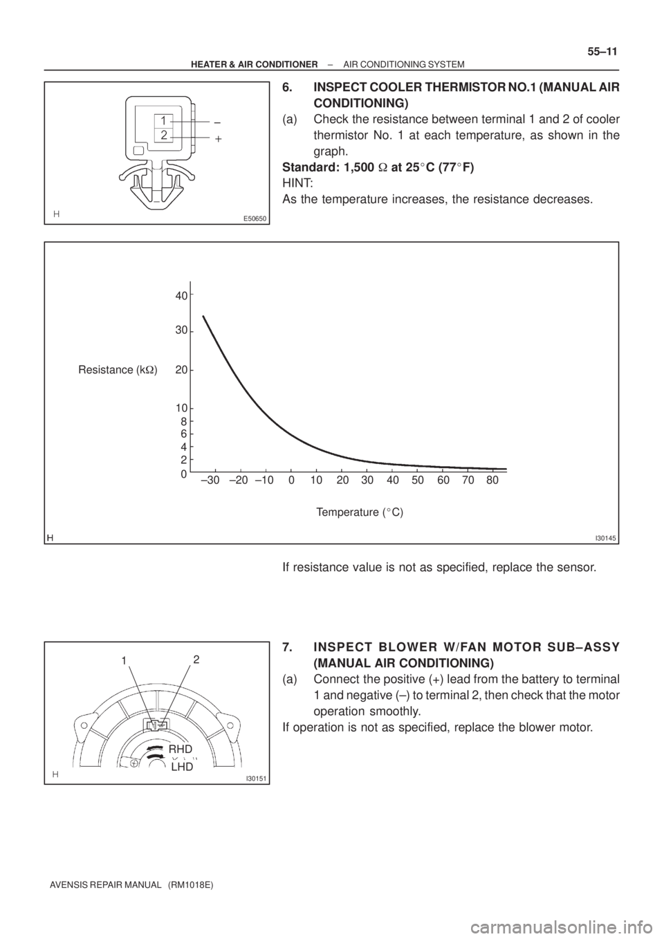
6. INSPECT COOLER THERMISTOR NO.1 (MANUAL AIR
CONDITIONING)
(a) Check the resistance between terminal 1 and 2 of cooler
thermistor No. 1 at each temperature, as shown in the
graph.
Standard: 1,500 � at 25�C (77�F)
HINT:
As the temperature increases, the resistance decreases.
If resistance value is not as specified, replace the sensor.
7. INSPECT BLOWER W/FAN MOTOR SUB±ASSY
(MANUAL AIR CONDITIONING)
(a) Connect the positive (+) lead from the battery to terminal
1 and negative (±) to terminal 2, then check that the motor
operation smoothly.
If operation is not as specified, replace the blower motor.

INSPECTION
1. INSPECT HEATER ASSY
(a) Inspe")

(d) Inspect the flame sensor.
(1) Using an ohmmeter, measur")

Vehicle Side SW 14
9
12
5
6
3
4
1")
DTC No.Comment / Remedy Description of fault
071Surface sensor break
Check connecting leads.
Resi")